MSTRONIC SOL10P12 Series User manual

Mstronic Co., Ltd.
SOL10P12 Series
Solar & PoE Battery Charger
USER’S MANUAL

User’s Manual SOL10P12 Series
Features:
Dual Input, from solar panel and/or PoE (Solar First) to charge 12V
battery, and another two outputs: PoE output on front and/or
terminal block on rear
Built-in DC/DC converter, with various passive PoE output, 24V,
48V, 56V available. (12V, 18V build to order)
Active PoE Output support 802.3at handshake
(SOL10P12-56A1N, SOL10P12-56B1N)
DIN Rail Mountable
Support Gigabit Ethernet
Applications:
Remote Power Systems; Surveillance, Sensors
Wireless Station; AP/Client/Repeaters
UPS Systems; Lighting, Fences, Gates
Protection:
Battery Polarity Reverse Protection
Battery Over Charge Protection
Battery Over Discharge Protection
Solar Panel Polarity Reverse Protection
Solar Panel Over Charge Protection
Output Short Circuit Protection
Output Over Voltage Protection
POE Output Short Circuit Protection
Externally fused with a standard replaceable fuse

User’s Manual SOL10P12 Series
Panel Description:
Item
Name
Descriptions
1
POE :
PoE power input indicator: the LED lights when the PoE input jack (the
lower jack) has 36V~57V input.
2
SOL :
Solar power input indicator: the LED lights when SOL terminal is
connecting to a solar panel and the solar panel input voltage is over 12V.
3
CHA :
Charging indicator: the LED lights when BAT terminal is connected to
battery and charging
4
LOA :
Loading indicator: the LED lights when the rear panel output terminal is
connecting to a device and offering power.
The LED always on when power ready.
5
REV :
Battery polarity reverse indicator: the LED lights when the battery
polarities are reversed. (detail description see Sec. 5.1)
6
IN :
PoE Input Jack: the lower RJ45 jack, used for PoE input. Allowed input
voltage 36~57V
7
OUT :
PoE Output Jack: the upper RJ45 jack, used for PoE output; Output
voltage depends on what model you selected.
8
FUSE
Fuse: for output over current protection, limiting the battery output current
<= 10A.
9
SOL :
Solar Panel Terminal: used to connect the solar panel.
10
BAT :
Battery terminal: used to connect the battery.
NOTE: ALWAYS CONNECT THIS TERMINAL FIRST.
If solar panel or PoE source is installed before the battery, and if the
polarities of battery are reversed, then the fuse will be burnt.
11
LOA :
Load Terminal: for wire size up to 10AWG, the output voltage is the same
as battery voltage.

User’s Manual SOL10P12 Series
Operation Guide
1. Connect the battery to the BAT terminal. Make sure the polarities are
correctly connected. Sequentially connect the solar panel to SOL terminal
and connect POE source to PoE input (lower) jack. (If solar panel or PoE
source is installed before the battery, and if the polarities of the battery be
reversed, then the fuse will be burnt.)
2. Make sure the battery is properly connected to the unit. If no battery is
connected, then the voltage at BAT terminal will be approx 13.8V
3. The solar panel cannot be used stand alone without battery connected.
4. When a solar panel and PoE input are connected to the charger, if the
voltage of solar panel is higher than 15V, then solar panel is always the
main power source of the charger.
5. When charge from solar panel, as the battery full and turn to floating
stage, the CHA light will start flash.
6. When charge from PoE, as the battery full, the CHA light will be turn off, if
the CHA is always flash, that means the input wattage lower than the
required minimum wattage. If only charge battery, the minimum input
wattage is 45W.
7. When battery connect to BAT terminal and with valid voltage, then the
LOA indicator will always light on even no load connected.

User’s Manual SOL10P12 Series
8. It can be two separate outputs on the rear panel, make sure the total
draw is not over the limit.
9. The V- of PoE input, Solar input, and battery(-) are not the same
grounding, must be properly isolated.

User’s Manual SOL10P12 Series
Electrical specifications
1. INPUT
1.1 Two Input Source:
A. Solar Panel : 18V~45V,
B. POE : 36 V~57V (only use 4 pairs injector for more than 35W input.)
2. OUTPUT
Model No.
Output 1
(at rear terminal)
Output 2
(at front/upper RJ45)
SOL10P12-24BNN
12V/10A
(as Bat. Volt.)
24V/1.25A
(45+/78-)
(regulated)
SOL10P12-48ANN
12V/10A
(as Bat. Volt.)
48V/0.625A
(12-/36+)
(regulated)
SOL10P12-48ANR
12V/10A
(as Bat. Volt.)
48V/0.625A
(12+/36-)
(regulated)
SOL10P12-48BNN
12V/10A
(as Bat. Volt.)
48V/0.625A
(45+/78-)
(regulated)
SOL10P12-56A1N
12V/10A
(as Bat. Volt.)
56V/0.625A
(12-/36+)
(regulated)
SOL10P12-56B1N
12V/10A
(as Bat. Volt.)
56V/0.625A
(45+/78-)
(regulated)

User’s Manual SOL10P12 Series
3. Battery Charge Current:
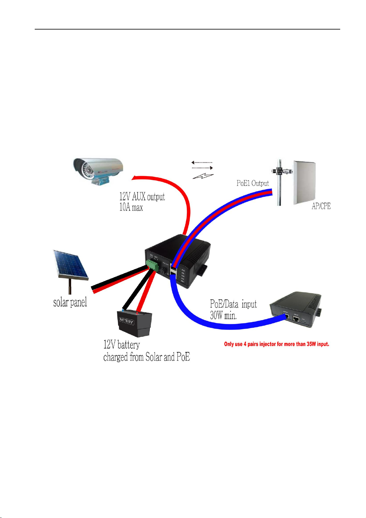
A. Solar Panel: depends on the solar panel, 10A max,
B. POE: fixed current, 2.0A max
4. Battery Types: 12V AGM Battery
5. Protection:
5.1 Battery Polarity Reverse Protection:
If only battery connected to terminal, when the battery polarities
were reversed, the model will stop output and REV indicator light
on.
When the battery be removed and re-connected to terminal, the
function will be disable, if there is PoE power sources connected,
when the battery polarities reversed, the fuse will be burnt.
5.2 Battery Over Discharge Protection:
Cuts off the load when the battery voltage is lower than 11V + 0.3V,
and auto recover when the battery voltage returns to 12 V + 0.3V
5.3 Battery Over Charge Protection:
Fuse control, over 10A, the fuse will be burnt.
5.4 Solar Panel Polarity Reverse Protection:
When solar panel polarities be reversed, the charger stop output, it
won’t damage the charger or end device
5.5 Solar Panel Over Charge Protection:
When charge current over 10A, the fuse will be burnt.

User’s Manual SOL10P12 Series
5.6 Output Short Circuit Protection:
When the rear output terminal or PoE output be short circuit,
protection be active, the product stop output and auto-recover
when the terminal back to normal connection.
5.7 Battery Output Current Limit:
The fuse will be burnt when battery output current over 10A
5.8 Load Output Voltage Limit:
The output voltage of the rear terminal is the same as battery.
5.91 POE Charge Voltage :
Float = 13.4V ± 0.2V
Equalize = 14.2V ± 0.2V
5.92 SOLAR Charge Voltage :
Charge Voltage = 14.4 V ± 0.2V
6. GENERAL DESCRIPTION
6.1 Operation Temperature: -40 - +60 Degree
6.2 Storage Temperature: -40 - +85 Degree
6.3 Operation Humidity: 5% - 90% non-condensing
6.4 Cooling: Free air cooling
6.5 SIZE 150*118*40mm (L*W*H)

User’s Manual SOL10P12 Series
7. Pin out: @1000M
RJ-45 Input (Data & Power)
Compliant to 802.3af/at
RJ-45 Output (Data & Power)
Depends on individual models
Pin
Symbol
Description
Symbol
Description
1
(+/-)Vdc + BI_DA+
power(+/-)+Data Pair A+
(+/-)Vdc + BI_DA+
power(+/-)+Data Pair A+
2
(+/-)Vdc + BI_DA-
power(+/-)+Data pair A-
(+/-)Vdc + BI_DA-
power(+/-)+Data pair A-
3
(+/-)Vdc + BI_DB+
power(+/-)+Data Pair B+
(+/-)Vdc + BI_DB+
power(+/-)+Data Pair B+
4
(+/-)Vdc + BI_DC+
power(+/-)+Data Pair C+
+Vdc + BI_DC+
power(+)+Data Pair C+
5
(+/-)Vdc + BI_DC-
power(+/-)+Data Pair C-
+Vdc + BI_DC-
power(+)+Data Pair C-
6
(+/-)Vdc + BI_DB-
power(+/-)+Data Pair B-
(+/-)Vdc + BI_DB-
power(+/-)+Data Pair B-
7
(+/-)Vdc + BI_DD+
power(+/-)+Data Pair D+
-Vdc + BI_DD+
power(-)+Data Pair D+
8
(+/-)Vdc + BI_DD-
power(+/-)+Data Pair D-
-Vdc + BI_DD-
power(-)+Data Pair D-
Note :
1. the model is isolated design, the output +/- or input +/- can be shorted
to ground (FG).
2. The PoE output can be 2 pairs or 4 pairs, depends on individual
models.
This manual suits for next models
6
Table of contents
Other MSTRONIC Batteries Charger manuals