Myenergi ZAPPI-2H07UB User manual

Rev 2.1.3 January 2022 – ENGLISH
eco-smart EV charge point
Operation & Installation
Manual
MODELS:
ZAPPI
-
2
H
07UW
ZAPPI-2H07UB
ZAPPI-2H07TW
ZAPPI-2H07TB
ZAPPI
-
2H22UW
ZAPPI-2H22TW
ZAPPI-2H22UB
ZAPPI-2H22TB

2 zappi operation and installation manual

Introduction
operation and installation manual zappi 3
Contents
Introduction.................................................................................................................................................................................................... 4
Safety .................................................................................................................................................................................................................................... 4
Box Contents ................................................................................................................................................................................................. 5
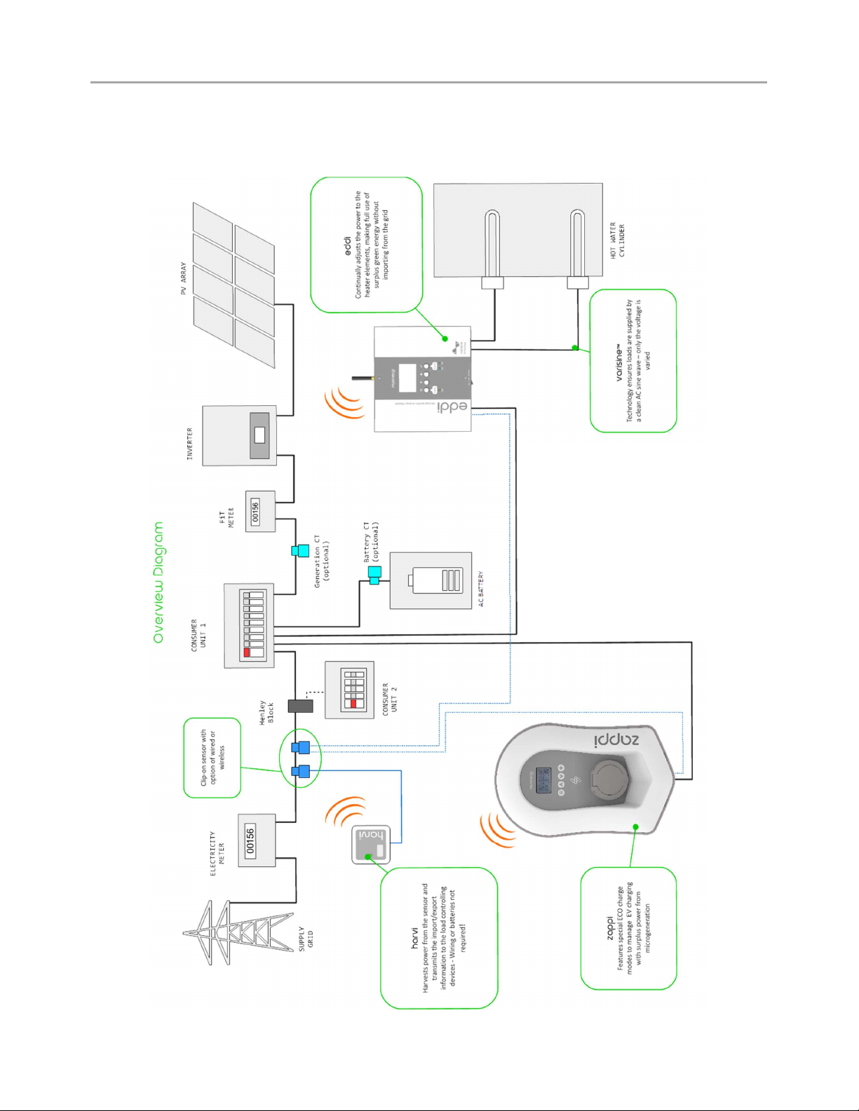
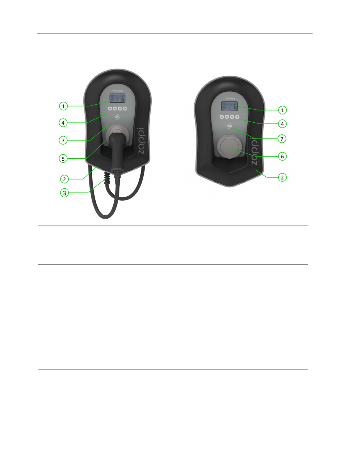
Overview ............................................................................................................................................................................................................................... 5
Operation ......................................................................................................................................................................................................... 7
Controls & Indicators........................................................................................................................................................................................................ 7
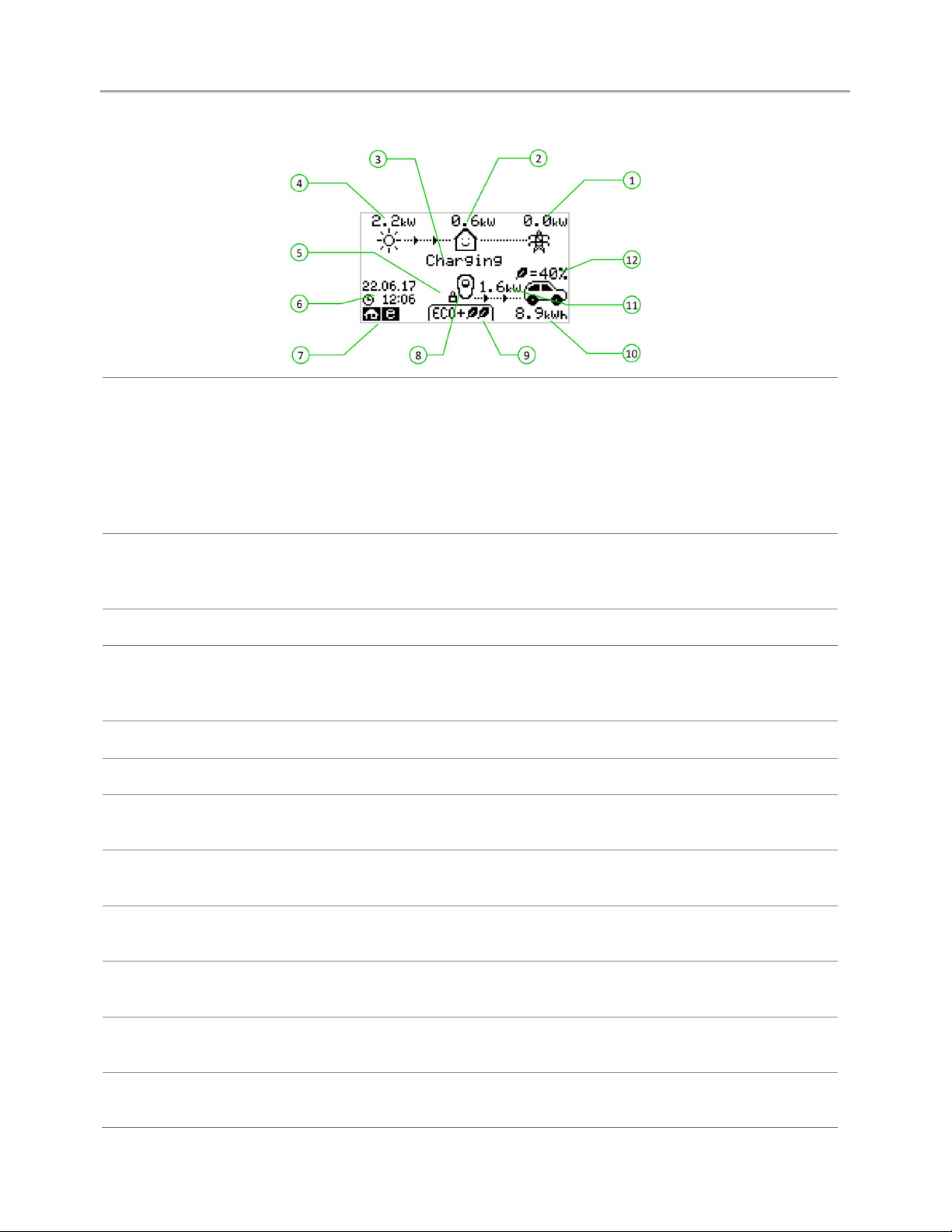
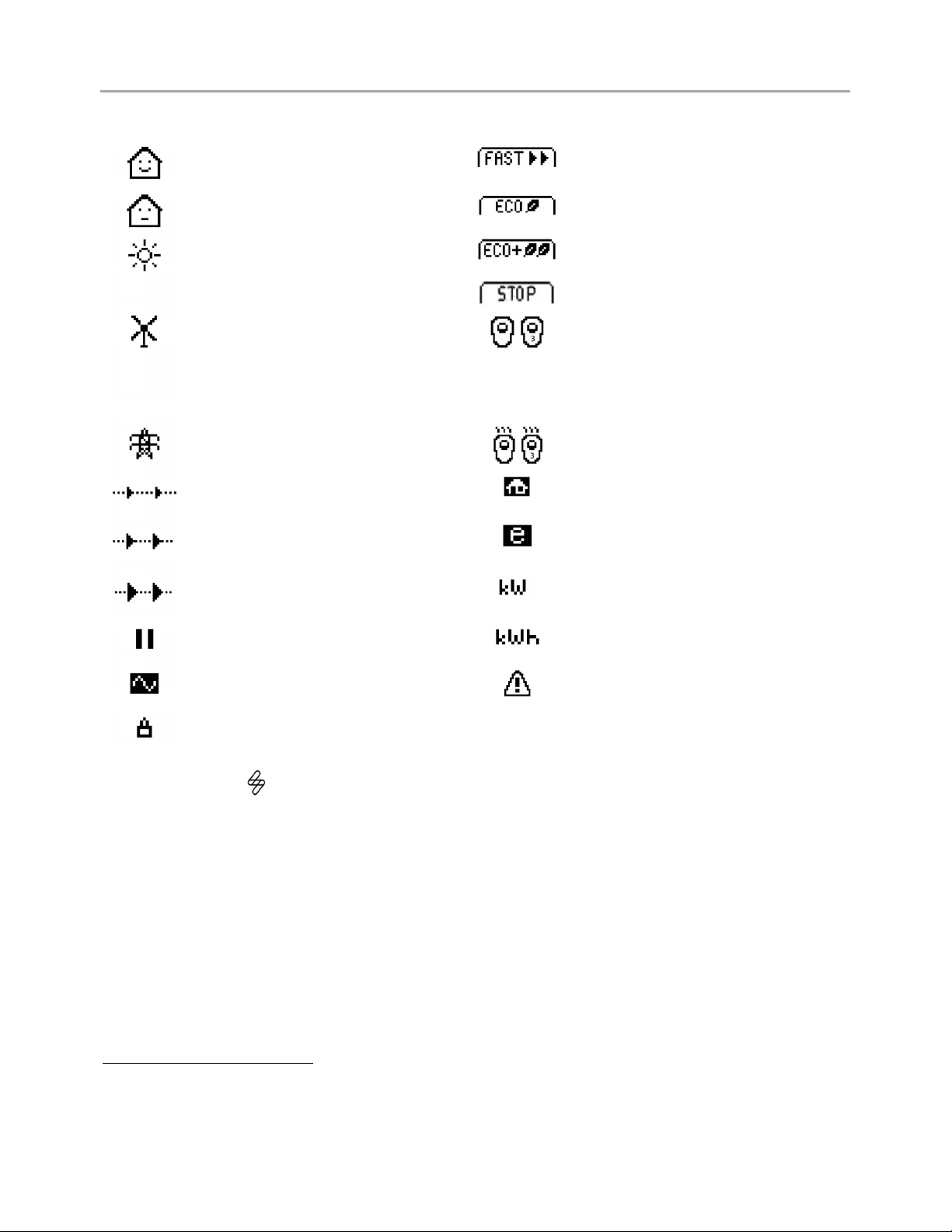
Display ................................................................................................................................................................................................................................... 8
Status Screens.................................................................................................................................................................................................................. 10
Charging Modes ............................................................................................................................................................................................................... 12
Manual Boost .................................................................................................................................................................................................................... 13
Smart Boost ....................................................................................................................................................................................................................... 13
Boost Timer ....................................................................................................................................................................................................................... 15
Lock Function ................................................................................................................................................................................................................... 16
Menus .............................................................................................................................................................................................................. 18
Main Menu .......................................................................................................................................................................................................................... 18
Advanced Menu ............................................................................................................................................................................................................... 22
Configuration Settings ............................................................................................................................................................................. 24
Time & Date ...................................................................................................................................................................................................................... 24
Display & Sound .............................................................................................................................................................................................................. 24
RGB LED ............................................................................................................................................................................................................................ 24
Grid Limit ........................................................................................................................................................................................................................... 24
CT Detect (“G100”) ........................................................................................................................................................................................................ 24
Advanced Settings .....................................................................................................................................................................................25
Supply Grid – Device Settings .................................................................................................................................................................................... 25
Supply Grid – Network Settings ................................................................................................................................................................................. 26
CT Config ............................................................................................................................................................................................................................ 27
Preconditioning ............................................................................................................................................................................................................... 29
eSense ................................................................................................................................................................................................................................. 31
Linking Devices ................................................................................................................................................................................................................ 31
Wireless Connection ...................................................................................................................................................................................................... 34
Ethernet Connection ..................................................................................................................................................................................................... 35
Installation .................................................................................................................................................................................................... 36
Electrical Installation..................................................................................................................................................................................................... 38
Wiring .................................................................................................................................................................................................................................. 39
eSense Input...................................................................................................................................................................................................................... 41
Wiring Overview Diagram ............................................................................................................................................................................................ 42
CT Sensor Installation ................................................................................................................................................................................................... 43
CT Golden Rules .............................................................................................................................................................................................................. 45
Fitting the Cover ............................................................................................................................................................................................................. 46
Advanced Installation Options ............................................................................................................................................................... 47
Built-in Protection ..................................................................................................................................................................................... 49
Setup ............................................................................................................................................................................................................... 51
Troubleshooting ..........................................................................................................................................................................................52
Faults .................................................................................................................................................................................................................................. 53
Warranty ........................................................................................................................................................................................................ 54
Product Registration ................................................................................................................................................................................. 54
Technical Specifications ......................................................................................................................................................................... 55
myaccount ....................................................................................................................................................................................................58
The myenergi app .......................................................................................................................................................................................58
The myenergi forum ..................................................................................................................................................................................58
Technical Support ......................................................................................................................................................................................58
Declaration of Conformity ....................................................................................................................................................................... 59

Introduction
4
zappi
operation and installation manual
Introduction
Thank you for choosing zappi. Of course, we think you have made an excellent choice and are sure you will be
incredibly happy with the features, benefits, and quality of your myenergi product.
These instructions will help you to familiarise yourself with the zappi. By reading the instructions, you will be sure
to get the maximum benefit from your 'eco-smart' device.
Safety
zappi is an AC EV charger, intended to be installed in a fixed location and permanently connected to the AC supply
network. It is a Class 1 item of electrical equipment in accordance with IEC 61140.
The unit is designed for indoor or outdoor use at a location with restricted access and should be mounted vertically
either surface (wall) mounted or on the dedicated pole mount supplied separately by myenergi.
The device has been manufactured in accordance with the state of the art and the recognised safety standards,
however, incorrect operation or misuse may result in:
Injury or death to the operator or third parties
Damage to the device and other property of the operator
Inefficient operation of the device
All persons involved in commissioning, maintaining, and servicing the device must:
Be suitably qualified
Have knowledge of and experience in dealing with electrical installations
Read and follow these operating instructions carefully
Always disconnect the device from the supply before removing the cover
The device is not to be used by persons (including children) with reduced physical, sensory, or mental capabilities,
or lack of experience and knowledge, unless they have been given supervision or instruction concerning use of the
device by a person responsible for their safety.
zappi comes in either tethered or untethered variants. The untethered version should only be used with a dedicated
cable fitted with a Type 2 plug which is compliant with EN 62196-1 and EN 62196-2. Adaptors or conversion adapters
and cord extension sets are not allowed to be used.
Failure to install and operate the zappi in accordance with these instructions may damage the unit and invalidate
the manufacturer’s warranty.
Disposal
In accordance with European Directive 2002/96/EC on waste electrical and electronic equipment and its
implementation in national law, used electrical devices must be collected separately and recycled in an
environmentally responsible manner. Ensure that you return your used device to your dealer or obtain information
regarding a local, authorised collection and disposal system. Failure to comply with this EU Directive may result in
a negative impact on the environment.
Copyright
Copyright of these operating instructions remains with the manufacturer. Text and images correspond to the
technical level at the time of going to press. We reserve the right to make changes. The content of the operating
instructions shall not give rise to any claims on the part of the purchaser. We are grateful for any suggestions for
improvement and notices of errors in the operating instructions.
myenergi zappi, myenergi eddi and myenergi harvi are registered trademarks of myenergi Ltd.

Overview
operation and installation manual zappi 5
Box Contents
Tethered Units
Untethered Units
1 x
zappi
unit with EV cable and connector attached
1 x Cable wall guard
1 or 3 x CT clamps0F1
1 x Mounting template
1 x Mounting kit for a brick wall
1 x
zappi
unit
1 or 3 x CT clamps1
1 x Mounting template
1 x Mounting kit for a brick wall
Mounting kit (Tethered units)
4 x 50mm Pozi screws
4 x Wall mounting plug
4 x Sealing washer
4 x 12mm Pozi screws (countersunk)
Mounting kit (Untethered units)
4 x 50mm Pozi screws
4 x Wall mounting plug
4 x Sealing washer
Overview
Microgeneration systems such as Solar PV and small wind turbines are at their most efficient when the generated
energy is consumed on-site rather than exporting it to the grid. This is what we call 'self-consumption'.
zappi is a Mode 3 charging station, compatible with all electric vehicles that comply with EN 62196 and EN 61851-1
plug-in electric vehicle standards.
zappi works like any regular charging point but has special ECO charging modes that will benefit homeowners with
grid-tied microgeneration systems e.g. wind or solar generation. Two special ECO charging modes automatically
adjust charging current in response to on-site generation and household power consumption. In FAST charge mode,
zappi operates like an ordinary EV charger.
A grid current sensor (supplied) simply clips around the incoming supply cable and is used to monitor excess power.
When using the special ECO charge modes, zappi will automatically adjust the charge rate in response to available
surplus.
Feature Set
3 charging modes: ECO, ECO+ & FAST
Optimises microgeneration self-consumption
Works with solar PV, wind turbine or micro-hydro systems
Economy tariff sense input
Programmable timer function
Charge and event logging
Remote control and monitoring add-on option
Pin-code lock function
Tap operated display backlight
Built-in 30mA Type A RCD + 6mA DC RCD protection (EN 62955)
Built-in protection against the loss of the protective neutral and earth (PEN) conductor as required by BS
7671:2018 Amendment 1:2020(The “Wiring Regulations”)
Ethernet connector (for local communications between myenergi devices)
Integral cable holster (tethered units)
Supplied with 1 x clip-on grid current sensor (x3 if purchasing a 3-phase unit)
Illuminated display – for convenience, the display can be illuminated by simply tapping the zappi front
cover.
Integrated WiFi for connecting to internet.
1 1xCT clamp supplied with single phase zappi; 3xCT clamps supplied with three phase zappi

Overview
6
zappi
operation and installation manual
Overview Diagram
The diagram below shows the zappi as part of a complete energy management system. Other myenergi products
are shown with details of how they integrate with the grid connection and the microgeneration system.

Operation
operation and installation manual
zappi
7
Operation
Controls & Indicators
1. Display Graphical LCD display with LED backlight
Backlight can be activated by tapping the unit.
2. Front Fascia Remove fascia for installing and servicing
3. Tethered Charging Cable if
applicable 6.5-meter cable with a Type 2 plug or Type 2 socket with locking system
for untethered models.
4. Control Buttons Four tactile buttons used to navigate the menus and alter settings:
Menu
Change charge mode | Move up a menu item | Increase value
Change charge mode | Move down a menu item | Decrease value
Boost | Select item | Confirm value and move to next setting.
5. Integrated Cable Holster
(tethered units only) When not in use, the charging cable should be wrapped around the unit and
secured in the cable holster (tethered units).
6. Charging Connection Point
(untethered units) When cable not in use, the charging cable should be unplugged and stored
in a cool dry place.
7. RGB Indicator Visual Indicator that changes colour dependant on the zappi's charging
state. (see RGB Indicator page 9)

Operation
8
zappi
operation and installation manual
Display
1. Import / Export Power The power being either imported or exported from or to the grid (kW). The
direction of the arrows indicates if the property is currently importing
power (left) or exporting power (right).
The size of the arrows is proportionate to the level of power being imported
/ exported, When the property is neither importing or exporting power the
figure will be 0.0kW and there will no animated arrows. The property is then
said to be 'in balance'.
2. House Load Power The power that the property is currently using in kW. (Note: This is displayed
only when the Generation Sensor is installed directly to a CT input or a
harvi
or other
myenergi
device)
3. Status Text The current status is displayed here (see Status Screens Page 12).
4. Generation Power The power being generated at this time in kW. (Note: This is displayed only
when the CTs are installed either hard wired to the CT inputs of the
zappi
or
wirelessly to a
harvi
or other
myenergi
device)
5. Lock Icon Operation lock is active.
6. Date & Time The current date and time.
7. Mode Icons These icons indicate that the import limiting is active (house), Demand Side
Response (~) or the eSense input is live (e) see page 44.
8. zappi Icon If you see wavy lines above the zappi icon, the unit is thermally limiting!
The output power is temporarily reduced.
9. Charge Mode Shows the selected Charging Mode; FAST, ECO or ECO+ (see Charging
Modes page 14).
10. Charge Delivered to EV The accumulated charge energy that has been sent to EV in this charge
session.
11. Current Charging Power When the EV is charging, arrows will show here along with the charging
power in kW.
12. Green Level of Last Charge This is the percentage of 'Green' energy for the last charge session, this is
shown at the end of a charge or when the EV is unplugged.

Operation
operation and installation manual
zappi
9
Display Icons Key
House Consumption
–
Not Importing
Charge Mode = FAST
House Consumption
–
Importing
Charge Mode = ECO
Solar Generation Power
Charge Mode = ECO+
Charge Mode = STOP
Wind Generation Power
zappi
Device
–
Normal
On the three phase zappi the number in
the icon indicates whether the EV is
charging with a single phase or all three
phases.
Grid Power
–
Import / Export
zappi
Device
–
Too Warm (output
limited)
Power Flow Direction
–
Small Amount
Import Power Limiting Active
Power Flow Direction
–
Medium Amount
Economy Tariff Electricity Available
Power Flow Direction
–
Large Amount
Current Charging Power
Waiting for Surplus Power
Energy sent to EV for this charge
DSR Mode (demand
-
side
response
)
2
Warning
–
refer to text on screen
Lock icon
–
zappi
or cable locked
(untethered versions only)
RGB Indicator
The lighting flash indicator on the front of the zappi indicates the status of the charge. The default colours are:
Pink: Connected
Green: Charging 100% Green
White: Charging from Grid only
Yellow: Charging mix of grid/green energy
Blue: Charge complete
Red: Error
These colours can be adjusted on Display & Sound menu (firmware version 2.163 onwards)
The colour effect (pulsing of the LED brightness) varies according to the charging power
2 DSR – Demand Side Response – A smart feature for future use by electricity suppliers and distribution companies
to help manage load on the electricity system at times of high demand. This feature can only be enabled by the owner
of the zappi

Operation
10
zappi
operation and installation manual
Status Screens
EV Disconnected
The EV is not connected to
zappi
.
In this example the last charging session delivered 20.8kWh of energy
to the EV and 80% of that energy came from the solar panels.
Waiting for Surplus
zappi
is waiting for sufficient surplus power from the microgeneration
system. This screen will be shown in ECO+ mode as it is only in this
mode that charging will stop if there is not enough surplus power.
The house in the centre is straight-faced as grid electricity is being
used by the house (0.9kW in the example shown).
Surplus
Enough surplus is available and
zappi
is about to charge the EV. A
timer is decremented and can be set in the charge settings (ECO+
mode only).
Waiting for EV…
zappi
is waiting for the EV to respond; the EV is not ready to accept
charge.
Charge Delayed
The charging session has
been delayed by the EV because a scheduled
charge has been set in the vehicle.
Paused…
zappi
is paused for a few seconds in order to limit the start/stop
frequency during ECO+ mode charging.

Operation
operation and installation manual
zappi
11
Charging
The EV is charging.
In this example the car is charging in ECO+ mode at 1.6kW, there is no
import or export from the grid (0.0kW) and the EV battery has charged
by 8.9kWh since the car started.
Charge Complete
The EV is fully charged.
The charge energy used during the last charge is displayed at the
bottom right (20.0kWh in this case) and the 'green contribution' is also
shown (40% in this example).
Restart…
zappi
is
performing
a restart sequence.
This may happen with some EVs that need to be 'woken-up' to start
charging after a pause in the charge. Charge should start immediately
afterwards, otherwise the “Charge Delayed” message will appear.
Stopping…
zappi
is about to stop the EV charging
Checking…
zappi
is carrying out a check to make sure that the built in RCD and
“PEN Fault” protection is working before starting to charge the car.
zappi carries out this before every charge so there is no need to
manually test the RCD protection.

Operation
12
zappi
operation and installation manual
Charging Modes
zappi has three different charging modes and a “STOP” mode which can be selected simply by pressing the and
buttons when the main screen is showing. The charge mode can be changed before or during a charge.
Regardless of the charge mode, all the surplus electricity is used. zappi's special eco charge modes limit the amount
of grid electric used. Below is explanation of each of the charging modes.
Charges at the fastest rate.
Fast Mode will charge the EV at the fastest rate and will import grid electricity if there is insufficient surplus
generated power.
The actual charge rate is dependent on the EV's onboard charger and the grid supply voltage. Some vehicles can
charge at 11kW or 22kW on a 3-Phase zappi, but many EV's have lower charge rates. The maximum charge rate for
the single phase zappi is 7kW.
Adjusts the charge rate to limit the use of electricity.
The charge rate is continuously adjusted, in response to changes in generation or power consumption elsewhere in
the home, thereby minimising the use of grid power.
Charging will continue until the vehicle is fully charged, using available surplus power.
If at any time, the available surplus power falls below 1.4kW, the shortfall will be drawn from the grid.
Note: The EV charging standard does not support charging below 1.4kW.
Adjusts the charge rate to limit the use of grid electricity and will pause the charge if there is too
much or any grid electricity being used (setup dependent)
The charge rate is continuously adjusted, in response to changes in generation or power consumption elsewhere in
the home, thereby minimising the use of grid power. Charging will pause if there is too much imported power,
continuing only when there is enough surplus power available. The surplus power threshold at which the charge will
start or stop can be set using Min Green Level in the ECO+ Settings of the Charge Settings menu.
The actual green contribution percentage is shown when the charge is complete or when the zappi has been
disconnected from the EV.
It is possible to charge the EV using only surplus renewable power, if there is sufficient surplus power available and
a boost option has not been set. (Please note: The EV charging standard does not support charging below 1.4kW)
Example: when zappi is set to a Min Green Level of 100% you will need in excess of around 1.4kW of surplus energy
available to start the charge. If the surplus falls below the 1.4kW threshold the charge will pause until the threshold
is once again met. After a short delay zappi will resume charge.
If preferable, you can set the zappi to share power from the grid and a generation source to ensure a charge is
always maintained. For example, the Min Green Level could be set to 75%. A charge will then start when there is a
surplus of 1.05kW, taking a further 0.35kW from the grid. It is worth noting that this is only required to start a
charge. If a higher amount of surplus becomes available it will be consumed, resulting in less being drawn from the
grid.
FAST
ECO
ECO+
STOP

Operation
operation and installation manual
zappi
13
The output from zappi is turned off
In STOP mode zappi will not charge your EV. This includes the boost modes and timed boost. zappi will continue
to measure power and communicate with the other myenergi devices.
Manual Boost
The Manual Boost function can only be used when charging in ECO or ECO+ mode. When boosting, the charge rate
is set to maximum (just like FAST mode), until a set amount of energy has been stored in the EV's battery. After
which, zappi will revert to ECO or ECO+ mode.
This function is useful if you arrive home with an almost flat battery and would like to charge the vehicle immediately
to ensure there is enough charge for a short trip if needed.
The amount of energy delivered to the EV during the boost charge can be changed in the Charge Settings/Boost
menu.
When in ECO or ECO+ mode, each press of the button will cycle through the boost options as illustrated below:
Activating Boost
1. When charging in ECO or ECO+ mode, press until BOOST is shown.
2. The boost will start after a couple of seconds and the display will show the remaining boost energy
The boost duration can be altered in the Charge Settings/Manual Boost menu option.
Cancelling Boost
The boost can be cancelled by pressing until Cancel Boost is shown.
Smart Boost
The Smart Boost function will charge the EV with a minimum kWh figure by a set time. Smart Boost is available only
in ECO and ECO+ modes.
The Smart Boost function does not bring the battery to a certain state of charge. The target kWh is only
the energy added during the charging session.
When in ECO or ECO+ mode, each press of the button will cycle through the boost options as illustrated below:
Example: It's a sunny Sunday and you wish to ensure there is enough charge in the EV to get to work in the morning
(e.g. 15kWh), but in the meantime, you want to use the surplus energy from the PV system to charge the car, so you
choose to use ECO+ mode. At sunset there was only 10kWh of charge accumulated. However, because you activated

Operation
14
zappi
operation and installation manual
Smart Boost, and set the time you needed to leave for work, zappi automatically boosted the charge in the night to
top up the battery to the required 15kWh by 7am.
Activating Smart Boost
1. When charging in ECO or ECO+ mode, press until SMART BOOST is shown.
2. The SMART BOOST icon will show including the target time and
the pre-set energy amount.
3. zappi will then test the EV for a few seconds, to determine the
maximum charge rate.
4. The boost will start at the latest possible time to achieve the set energy amount, if the current charge
session has already accumulated enough energy, the boost will not be required and so will not operate.
The required energy and target time can be altered only when Smart Boost is not active. These settings are
in the Charge Settings/Smart Boost menu option.
Cancelling Boost
The boost can be cancelled by pressing until Cancel Boost is shown.
Programming the Smart Boost Values
1. From the main screen, press to enter Main Menu
2. Select Smart Boost from within the Charge Settings menu. The SMART BOOST screen is then shown
3. The boost can now be edited: Use or buttons to edit the target time and amount of charge
(kWh) that is required
4. Use the to move to the next value, and the to return to the main screen once the required
Smart Boost parameters have been set

Operation
operation and installation manual
zappi
15
Boost Timer
When using ECO or ECO+ charge modes, zappi can be programmed to 'boost' the current charge at certain times.
When boosting, the charge rate is set to maximum (just like FAST mode), regardless of the amount of available
surplus power. This means that power may be drawn from the mains grid supply during boost times.
There are four editable time slots which can be set to operate for certain days of the week.
Setting the duration to 0h00 will make the boost inactive.
Programming Boost Times
1.
From the main screen, press
to enter
Main Menu
2.
Select
Boost Timer
from within the
Charge Settings
menu. The
BOOST TIMER screen is then shown.
3.
The boost can now be edited: Use
or
buttons to highlight
the time slot you wish to change. The lower screenshot shows
the start hour being edited:
4.
Alter the start hour with the
or
buttons and then press
to move to minutes.
5.
Edit the duration in the same way and then press
again to
edit the days of the week you want the boost to be active for.
Each day of the week can be toggled on/off with or
buttons. Press to go to the next day. Pressing on the last
day (Sunday) will confirm the boost time slot and the whole line
will be highlighted again.
6.
Press
to exit the
BOOST TIMER
screen.
Economy Tariff Boosting
Boosting only when economy rate electricity is available can be achieved in one of three ways:
1. By setting the boost timer to coincide with the economy tariff times. This option should be used only
if the electricity meter is a dual
-
rate meter (modern meters usually are).
2. Boost only at set times AND if economy rate electricity is available.
3.
Automatically boost whenever the economy tariff rate electricity is available, regardless of boost
times*
*Options 2 and 3 are available only when using the eSense input.
For option 1, the eSense Input in the Advanced menu should be set to Boost
Timer Enable.
With the Boost Timer Enable function set, the BOOST TIMER screen will include
an extra column. The e can be toggled on/off. If e is present, the boost will
activate only when the boost times are valid and the economy rate tariff is
available.
Alternatively the eSense input can be used to activate the boost whenever the economy tariff rate electricity is
available, regardless of boost times (option 2). To do this, the eSense Input option in the Advanced menu should be
set to Boost. When using this option, the Boost Timer is not needed.

Operation
16
zappi
operation and installation manual
Boost Time Conflicts
If one or more boost times conflict, the boost will follow the latest time or longest duration.
Lock Function
zappi can be locked from unauthorised operation. The Lock Function requires a PIN number to be entered before
the unit can be operated and/or a charge is allowed. The main display can also be hidden when zappi is locked.
The lock can be set to be active
– Only when the EV is plugged in
– Only when the EV is unplugged.
– All the time.
The settings for the Lock Function can be found in the Other Settings/Lock Function menu option.
Lock Function Setting
Description
EV Plugged The Lock Function is active when the EV is plugged in, preventing tampering with the
charge session, or changing any settings
EV Unplugged The Lock Function is active when the EV is disconnected, preventing unauthorised
charging
If
EV Plugged
and
EV Unplugged
are both
set,
then
the PIN lock is always active.
zappi is effectively locked against any unauthorised use and the PIN code will always be required to make any
changes locally or to start a charge.
These are the recommended settings if zappi is mounted in an exposed / publicly accessible location and you
do not want anyone else to be able to use it.
Timeout The time before the Lock Function automatically reactivates after being unlocked
Lock Code This is the current lock code and is five digits from (1 to 4), it can be changed here
Default code: 44444
Auto Hide If set, this will hide the main display of the zappi to keep the power readings private
Charge: Allow a charge session without the need to enter a pin-code. Useful to leave zappi
access free but with the settings protected.
Test Tests the socket lock solenoid when the charging cable is not plugged in.
If zappi will be used to provide public access for EV charging, then it is recommended to use the following
settings:
EV Plugged – On
EV Unplugged – On
Charge – On
Lock Code – changed to a private PIN number
Socket Lock
For untethered units only, the EV cable will be locked automatically when it is inserted into the zappi, even if it is
not plugged into the EV. A small ‘lock’ icon will be seen on the right side of the zappi, in the centre of the screen.
When the EV is disconnected, a press of the button, will unlock the cable for a duration of 5 seconds, allowing the
cable to be removed from zappi. After this time, the lock will be re-activated.

Operation
operation and installation manual zappi 17
If the ‘Lock Function’ (PIN lock) feature is enabled in the zappi, the cable will not be locked into the socket until the
PIN is entered and EV charging starts. This means that if anyone plugs their cable into the zappi but they do not
know the PIN they are able to remove their cable.
In all cases the cable is unlocked if zappi detects a fault or the power supply to the zappi is switched off.

Menus
18 zappi operation and installation manual
Menus
Main Menu
Main Menu Options
Description
Charge Log… Today… Log of Charge Sessions
Yesterday…
Week…
Month…
Year…
Total…
Custom Date…
Event Log… Today… Log of Events
Yesterday…
Week…
Custom Date…
WCS…
Readings… Readings 1/9 Status: Mode: Current status and charging mode of the unit
Exporting:
Importing:
Power being exported or imported, from or to the grid
respectively
Charging: Power level in Watts being supplied to the EV
Pilot (PWM): Control Pilot PWM
Charge Current: /
I(A) AC current supplied to the EV
Unit Temp: Internal temperature of the zappi unit
Readings 2/9 Voltage: Supply voltage to the unit
Voltage Max: Maximum supply voltage since switch-on
Voltage Min: Minimum supply voltage since switch-on
Frequency: Grid frequency
Exporting:
Importing:
Power being exported or imported, from or to the grid
respectively
PH1 PH2 PH3 Indicates which phases are active when charging
Readings 3/9 Exporting:
Importing:
Power being exported or imported, from or to the grid
respectively
Generation: Power from the generator (if available)
Consumption: Power consumed by the house (if available)
Diverted: Total diverted energy (inc. all myenergi devices)
Charging: Current power being supplied to the EV
Charge Energy: Energy supplied to the EV during current charge
session
Time: Duration of the current charge session
Readings 4/9 Exporting:
Importing:
Power being exported or imported, from or to the grid
respectively

Menus
operation and installation manual zappi 19
Battery: If an AC battery is being monitored the batter power
reading is shown:
Discharging (+) Charging (-)
Britain GMT/BST The set time zone
LOC: Local time
UTC: Coordinated Universal Time
Readings 5/9 CP (Control Pilot) related debug information
Readings 6/9 DSR related debug information
Readings 7/9 Power Readings Debug screen in preparation for automatic switching
between a single phase and three phase charging
Readings 8/9 Packet Counters Displays activity over the wireless and Ethernet links
Information…
Information 1/5 Status: Status of the unit
Serial No: Serial number of the unit
Firmware: Firmware version installed in the unit
Assembled: Factory assembly date
Cal Date: Calibration changed date
Power Fail: Time and date of last supply failure
Information 2/5
Grid Sensor: Grid current sensor source
Last Fault: Last recorded fault code
Fault Date: Date and time of last recorded fault code
zappi 1ph
Untethered
zappi 1ph Tethered
zappi 3ph
Untethered
zappi 3ph Tethered
zappi 3ph!
Identifies the zappi type, e.g. 3 phase or single phases
/ tethered or untethered.
A '!' mark shows a missing phase for 3 phase units
Information 3/5
Network ID: Network information for this device when linked to
other devices using myenergi radio frequency (RF)
network (Only shows if connected to other devices)
Device Address:
Master Address:
Channel:
EUI:
MNID:
EV: Active: Auto updates on 3 phase zappis following the first
charge session to indicate if the EV is capable of
charging with 3 phases and whether 1 phase or 3
phase charging is active
Information 4/5
Time: Current time
Date: Current date
Up Time: Length of time passed since last switch on
Network load control limiting information:

Menus
20 zappi operation and installation manual
DDL:
II:
LGA:
MGA:
DSR:
DDL = Dynamic
Device
Limit (A)
II = Input current (Amps)
LGA = Load Group Limit Active (Y/N)
MGA = Monitor Group Active (Y/N)
DSR = Demand Side Response Active (Watts and time
to live)
See Load Balancing / Current Limiting (page 52)
Information 5/5
IP:
Mask:
Route:
DNS:
DirIP:
Cloud:
OFWIP:
Details of Ethernet connection (if zappi has an active
Ethernet connection) plus IP addresses of myenergi
servers
Linked
Devices
Info…
Devices PWR Now Power currently being drawn by the linked devices
Devices PWR Allott Available power allotted to the linked devices
Devices PWR Max Maximum power that can be used by each device
Devices PWR Min Minimum power that can be used by each device
Devices Misc Further information about power allocation of linked
devices:
Total Allotted = Total power allotted to all devices
Total Loads = Power consumed by all devices
Surplus Power = Unallocated power
O/D Power = Total power over-drawn by devices
Export Timer = Delay before surplus is allocated
Charge
Settings… ECO+
Settings… Min Green Level: ECO+ charge mode settings
Start/Stop Delay:
Plug-in Charge Allows zappi to force a charge session the first time the
EV is plugged in. Required by some EV’s if main charge
does not start immediately.
Manual Boost… Manual Boost settings. See Manual Boost page 15.
Smart Boost… Smart Boost settings. See Smart Boost page 15.
Boost Timer… Programmable boost times. See Boost Timer page 18.
Preconditioning… Configure how zappi respond if the EV starts
preconditioning once the previous charge is complete.
See Preconditioning Page 32.
Default Mode: Can be set to "FAST / ECO / ECO+ / MEM" (MEM stands
for memory, i.e. last set mode before zappi reset
ECO/ECO+ Sets the number of phases for ECO & ECO+ charge
modes (only available on 3 phase zappi)
Other
Settings… Time & Date… Time: Sets the current time in 24-hour format
Date: Sets the date in Format (see below)
Format: Sets the format of the date
This manual suits for next models
7
Table of contents
Other Myenergi Batteries Charger manuals