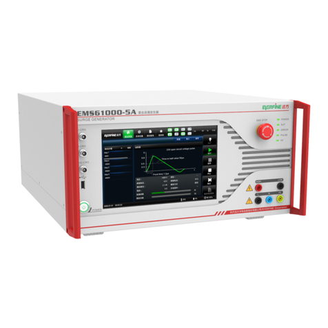
Everfine EMS61000-2A User manual

EMS61000-2A
ESD GENERATOR
USER’S MANUAL
V 4.02
EVERFINE Corporation (Stock Code: 300306)
ADD :Bldg.1 #669 Binkang Rd., Binjiang Hi-Tech
Zone, Hangzhou(310053), China
Tel :86-571-86698333
Fax :86-571-86696433
E-mail:Global@everfine.net
Globalservice@everfine.net
http://www.everfine.net
Copyright © EVERFINE, Copy or spread without authorization is prohibited.


EMS61000-2A User’s Manual
Copyright © EVERFINE, Copy or spread without authorization is prohibited. 1
Foreword
Thank you for purchasing the EVERFINE EMS61000-2A_30kV ESD Generator. This
user’s Manual contains useful information involving the instrument’s functions and
operating procedures as well as precautions that should be noticed during operation.
In order to use the instrument correctly, please read the manual carefully first, then put
it in a right place for quick references.
Notes:
The contents of this manual may be changed without prior notice.
Great effort has been made in preparation of this manual to ensure the accuracy of
its contents. If you have any questions or find any errors, please contact your
dealer or EVERFINE sales office.
If you have different understanding to this manual, please refer to the Technical
Service Department of EVERFINE.
Checking package contents
Please check the instrument carefully when you unpack the box for the first time. If
the instrument and related accessories are missing or appear abnormal, please contact
the dealer or EVERFINE immediately.
Warm notice to valued customers of EVERFINE
"Ensure the quality, insist on continuous improvement and make every customer
more satisfied" is the quality policy of EVERFINE. Therefore, the quality of
products and services provided by EVERFINE should be better than those have
been promised. If you have further suggestions or advices on our products and
services, please provide your feedback to our quality supervision department.
Your supervision is the motivation for us to move forward!

EMS61000-2A User’s Manua
Copyright © EVERFINE, Copy or spread without authorization is prohibited.
2
Copyright Statement
The copyright of this manual and the related information belongs to EVERFINE,
and it is protected by the copyright law of Peoples Republic of China and other
relevant international treaties. Copying, modifying, spreading, excerpting, backing up
and translating the whole or part contents of this manual by any company or personnel
without the written permission of EVERFINE is prohibited. Otherwise it will be
treated as infringement and the infringer will assume law responsibility and all loss of
EVERFINE. Any infringement related above can be traced back to the responsible
user by the unique product number printed in the manual.
If EVERFINE has signed a written agreement with user and the contents in the
agreement are in conflict with above terms, the contents in the written agreement have
preferential force effect.

EMS61000-2A User’s Manual
Copyright © EVERFINE, Copy or spread without authorization is prohibited. 3
Safety regulation
The following general safety precautions must be observed during all phases of
operations, including verification and repair. If the instrument is used in a manner not
specified in this manual, the function of this instrument may be hindered.
Flags below are adopted in the instrument.
High-voltage
Ground
Warnings
Never use the instrument in an explosive environment
Never use the instrument with explosive, gunpowder and firecracker around.
Using any electrical appliance in the explosive environment may be harmful.
Protecting Grounding
Ensure the instrument has been well grounded before turning on the power to avoid an
electric shock. Avoid taking the zero line of alternating current as the protective
grounding.
Power Supply
Make sure that the rated voltage of the instrument is equal to the voltage of the power
before connection.
Only lithium battery charger will be supplied and the lithium battery should be setted
when instrument is on operation.
Maintenance of the lithium battery
The battery should be charged/discharged every 3 months and it should be 60% power
left at least before store again. It should be charged within 24 hours if it is turned off
as the power shortage, otherwise, the battery would be damaged.
If the battery needs to be changed, please contact the retailer or EVERFINE.
Vents

EMS61000-2A User’s Manua
Copyright © EVERFINE, Copy or spread without authorization is prohibited.
4
Vents provide necessary cooling channel and should not be blocked when instrument
is on operation.
DO NOT take away any parts of the case
Since the instrument works at a high voltage, never remove the case of the instrument
or operate with the case opening.
Relative humidity
Never operate the instrument with wet hands or in an environment with high
humidity.
Transport
Take care when moving the instrument, and avoid collision, vibration or placing the
instrument upside down.

EMS61000-2A User’s Manual
Copyright © EVERFINE, Copy or spread without authorization is prohibited. 5
Contents
Foreword........................................................................................................................ 1
Copyright Statement.......................................................................................................1
Safety regulation.............................................................................................................3
Contents..........................................................................................................................5
Chapter 1 Overviews...................................................................................................... 7
Chapter 2 Specifications.................................................................................................8
2.1 Main specifications............................................................................................8
2.2 Conventional specification................................................................................ 9
Chapter 3 Panel Instructions.........................................................................................11
3.1 Front panel.......................................................................................................11
3.2 Rear panel........................................................................................................12
Chapter 4 Parameters Setting....................................................................................... 13
4.1 Interface and Parameters Setting..................................................................... 13
Chapter 5 Operation..................................................................................................... 22
5.1 Preparations..................................................................................................... 22
5.2 Power ON........................................................................................................ 22
5.3 Test parameter setting......................................................................................22
5.4 Starting test......................................................................................................22
5.5 Test termination............................................................................................... 23
5.6 Ending test....................................................................................................... 23
5.7 Altering information and its countermeasures.................................................23
Chapter 6 Verification...................................................................................................26
6.1 Verification basis............................................................................................. 26
6.2 Verification conditions.....................................................................................26
6.3 Verification of ESD high voltage output......................................................... 26
6.4 Verification of ESD gun.................................................................................. 27
Chapter7 Set-up in laboratory...................................................................................... 31

EMS61000-2A User’s Manua
Copyright © EVERFINE, Copy or spread without authorization is prohibited.
6
7.1 Test set-up in laboratories................................................................................31
Chapter 8 Driver installation........................................................................................ 35
8.1 Internet driver installation............................................................................... 35

EMS61000-2A User’s Manual
Copyright © EVERFINE, Copy or spread without authorization is prohibited. 7
Chapter 1 Overviews
EMS61000-2A ESD Generator is a highly reliable test system specially designed
according to the characteristics and requirements of ESD immunity test, with built-in
lithium battery and portable design. The maximum ESD voltage is up to 30 kV and
meets the highest severity level requirements of the standards, and provides an
accurate and satisfactory basis for the immunity assessment of electrical equipment
subject to electrostatic discharge.
EMS61000-2A ESD Generator meets requirements of standards such as ICE610
00-4-2, ISO10605. Equipped with different modules, EMS61000-2A ESD genera
tor can output international standard of ISO discharge models.
Main characteristics of EMS61000-2A:
1. With built-in lithium battery, portable and convenient to use.
2. Test voltage can up to 30KV maximum.
3. Identify the discharge resistance/capacitance modules intelligently to conduct
ESD test.
4. With discharge detection function, its sensitivity can be adjusted.
5. 7 inch LCD touch screen displayer and computer interaction interface.
6. With file systems, export and save test reports conveniently.
With RJ45 and USB communication Function.

EMS61000-2A User’s Manua
Copyright © EVERFINE, Copy or spread without authorization is prohibited.
8
Chapter 2 Specifications
2.1 Main specifications
(1) Electrostatic voltage
Polarity: positive/negative/alternate
Output voltage: up to 30.00kV±5%
Resolution: 0.01kV(10.00kV~30.00kV)
(2) Discharge interval
Contact discharge: 0.050s~30.0s
Air discharge: 1.0s~30.0s
(3) Discharge count
1~9999 when discharge interval is larger than 0.1s
1~100 when discharge interval is less than 0.1s
(4) Trigger mode
Manual: discharge one time when triggering the discharge gun or discharge button of
trigger module
Auto: continuously discharge as setting interval
External: discharge one time when receive an external trigger signal.
(5) Discharge network
Discharge network are listed in Table 2.1.
Table.2.1 Discharge network setting
Discharge
mode
Discharge
network
Max electrostatic
voltage
Standard
Remark
ISO
330Ω/150pF
±30.00kV
ISO10605
ESD gun
(optional)
330Ω/330pF
±30.00kV
ISO10605
2000Ω/150pF
±30.00kV
ISO10605/IEC61000-4-2
2000Ω/330pF
±30.00kV
ISO10605

EMS61000-2A User’s Manual
Copyright © EVERFINE, Copy or spread without authorization is prohibited. 9
HBM
1500Ω/100pF
±8.000kV
±20.00kV(Optional)
ANSI/ESD STM5.1;
EIA/JESD22–A114;
HBM
MM
0Ω/200pF
±800V
±4.000kV(Optional)
ANSI/ESD STM5.2;
EIA/JESD22–A115;
MM
(6) Discharge waveform
Parameters of discharge waveform are listed in Table2.2.
Table.2.2 Parameters of discharge waveform
Discharge
network
Peak
current
/Dischar
ge
voltage
A/kV
Accuracy
%
Current@t1/
Discharge
voltage
A/kV
Accuracy
%
Current@t2/
Discharge
voltage
A/kV
Accuracy
%
330Ω/150pF
3.75
±10
2
(@t1=30ns)
±30
1
(@t2=60ns)
±30
330Ω/330pF
3.75
±10
2
(@t1=65ns)
±30
1
(@t2=130ns)
±30
2000Ω/150pF
3.75
+30
0
0.275
(@t1=180ns)
±30
0.15
(@t2=360ns)
±50
2000Ω/330pF
3.75
+30
0
0.275
(@t1=400ns)
±30
0.15
(@t2=800ns)
±50
(7) Endurance ability
Battery life is more than 2 hours.
2.2 Conventional specification
(1) Environment temperature: 25℃±10℃
(2) Relative humidity: 20%~60%R.H.
(3) Power supply : 100~240VAC,50Hz/60Hz
(4) Battery(build-in): When the instrument is not connected to the charger,its
power supply is provided by built-in lithium battery .
When instrument connects to AC power supply,the

EMS61000-2A User’s Manua
Copyright © EVERFINE, Copy or spread without authorization is prohibited.
10
instrument is charged by AC and battery will charged
automatically.
(5) Dimensions: 300mm×200mm×200mm(W×H×D)
(6) Weight: About 7.0kg

EMS61000-2A User’s Manual
Copyright © EVERFINE, Copy or spread without authorization is prohibited. 11
Chapter 3 Panel Instructions
3.1 Front panel
Fig.3.1 Front panel of EMS61000-2A ESD Generator
1Power Switch and Indicator
Switch for power supply of instrument.
Indicator is green:Power ON
Indicator is orange:Power OFF and be charged
normal
2LCD Screen
Set parameter and show information
3ESD module connector
Connect with ESD module, output the high
voltage and control signal output end

EMS61000-2A User’s Manua
Copyright © EVERFINE, Copy or spread without authorization is prohibited.
12
3.2 Rear panel
Fig.3.2 Rear panel of EMS61000-2A ESD Generator
1Vents
Instrument’s cooling channel and strictly prohibited
to be blocked when on operation.
2Ground
Ensure the instrument has been well grounded
before turning on the power.
3EXT-TRIG
External trigger input terminal
4EUT-FAILED
EUT-failed input
5TRIG-CRO
Trigger output terminal
6USB-B
Communication with computer by USB line
7USB-A
Export test report by connecting to USB disk
8RJ45
Communicate with computer by RJ45
9Power supply connector
Input power and need connect to appropriative
charger
10 Battery bin
Place the special battery

EMS61000-2A User’s Manual
Copyright © EVERFINE, Copy or spread without authorization is prohibited. 13
Chapter 4 Parameters Setting
4.1 Interface and Parameters Setting
4.1.1 Main interface
Fig.4.1 Main interface of EMS6100_2A
①System setting
Set up and edit related parameter
information of the instrument
②Dynamic display section
Display present discharge voltage
③Parameters setting
Set up test parameters
④Test procedure display section
Display test steps
⑤Progress bar display section
Display current test progress
⑥Run buttons
“Run”:The run button
“Pause”:The pause button
“Reset”:The stop button
⑦Environment information display section
Display ambient temperature,
humidity
⑧Charging indicator display section
Display the charger’s connection
information
⑨Left power charge display section
Display the battery level

EMS61000-2A User’s Manua
Copyright © EVERFINE, Copy or spread without authorization is prohibited.
14
For resetting parameters, it can be achieved in parameter setting interface and refer to
specifications of corresponding function setting part to finish other parameters setting.
Press the “Run” button to start test after parameters setting is completed.
4.1.2 System setting section
Fig.4.2 System setting section
①New button
Create a new test program
②Open button
Open an existed test program
③Save button
Save the present test program
④Report button
Edit and export test report
⑤Setup button
Setting up general parameters
⑥Help button
Show information of the instrument
1.“Open”tab
Fig.4.3 Test program interface
Click on the “Open” tag in figure 4.2 and the pop-up window shown as figure 4.3.

EMS61000-2A User’s Manual
Copyright © EVERFINE, Copy or spread without authorization is prohibited. 15
①Program list
Show all the system programs
②“Std” tab
Click to enter into the standard program library
③“User” tab
Click to enter into the user-defined program library
④Edit button
“Pg up”: turn back to the former page of the program list;
“Pg dn”: turn to the latter page of the program list;
“conf”: download the selected program to the main
interface and return to the main interface;
“Rtn”: back to the main interface.
Click on corresponding program shown inof figure 4.3 to rename the program, then
click on the corresponding program name and dialog box will be pop-up as shown in
figure 4.4. Click the name in pop-up dialog box to get qwerty keyboard shown in
figure 4.4, then program name can be modified through the qwerty keyboard.
Fig.4.4 Testing program rename interface
Notes: Click on “Enter” to affirm input;
Click on “Esc” to quit input state;
Click on “Caps” to switch the capital and small letters.

EMS61000-2A User’s Manua
Copyright © EVERFINE, Copy or spread without authorization is prohibited.
16
2. “Report” tab
Fig.4.5 “Report” button interface
Click on “Report” tab in ⑤of figure 4.2 and the pop-up window is shown as figure
4.5.
①Report list
Display the saved system test report;
②Report tab
Edit title of the test report;
③“Export” tab
Export test report to USB driver via USB
port; The export report can be printed by
EmcSuite software;
④Edit button
“Pg up”: turn back to the former page of
the program list;
“Pg dn”: turn to the latter page of the
program list;
“Del”: delete the selected test report;
“Rtn”: back to the main interface.
Click on the corresponding number shown in ①of figure 4.5, select the
corresponding test report and operate “del”; Click on corresponding title in section ②,
enter report edit interface shown in figure 4.6 and edit the report content. Only
English and common character are supported.

EMS61000-2A User’s Manual
Copyright © EVERFINE, Copy or spread without authorization is prohibited. 17
Fig.4.6 Report edit interface
3. “Setup” tab
Fig.4.7 “Setup” tab interface
Click on “Setup” tab of ⑥in figure 4.2 and the window will be popped-up as shown
in figure 4.7, then relevant functions can be set up as “ON and OFF”. Settings and
their functions are specified in the following Table 1.
Table4.1 Settings function specification
Settings
Setting contents
Notes
Language
Chinese/English
Setting instrument’s language
EUT failed
detection
ON/OFF
EUT failure detection ON/OFF

EMS61000-2A User’s Manua
Copyright © EVERFINE, Copy or spread without authorization is prohibited.
18
Time
Time/Date
Setting instrument’s time and date
Discharge
sensitivity
High/Middle/Low
High: Count when detecting larger
discharge current, maybe without
discharge spark;
Middle: Count when detecting
discharge spark;
Low:Count when detecting discharge
spark, maybe discharge continuously;
Adjust
Input password
Calibration instrument only for
manufacturer
4. “Help”
Fig.4.8 “Help” tab interface
Click on the “Help” tab of ⑦in figure 4.2 and the window will be popped-up as
shown in figure 4.8. Communication and language can be set up in this interface.
Click on the “waveform” label and it will display standard waveform figure.
4.1.3 Dynamic display interface
Fig.4.9 Dynamic display interface
Table of contents
Other Everfine Portable Generator manuals
Popular Portable Generator manuals by other brands

Red-D-Arc
Red-D-Arc RDA150T3 Service manual
Scheppach
Scheppach SG3400i Translation from the original instruction manual

Champion Power Equipment
Champion Power Equipment Power Sports 73538i Owner's manual & operating instructions
Champion
Champion 71001I EU Owner's manual & operating instructions
Briggs & Stratton
Briggs & Stratton 030208-1 Illustrated parts list
DUROMAX
DUROMAX XP15000E user manual
