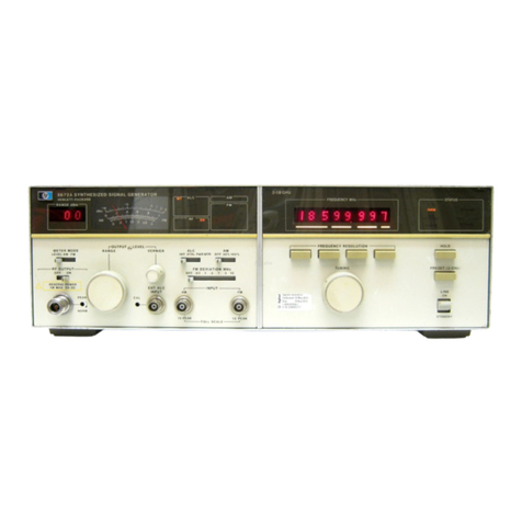
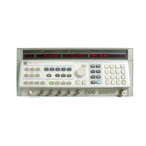
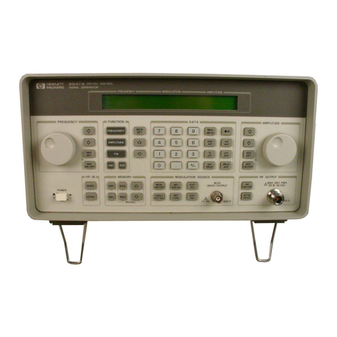
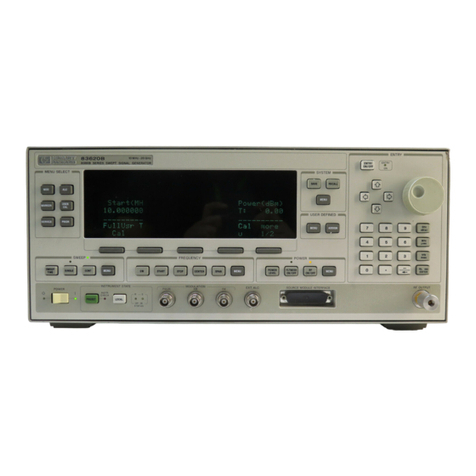
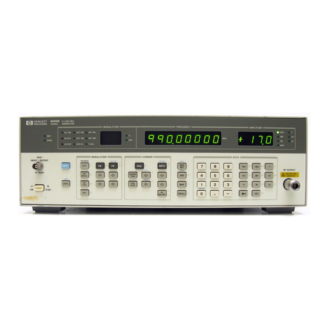
HP 8656 Series Instruction manual

HP
8656157
Series
Economical Synthesized
Signal
Generators
Analog
and
Digital
Modulation
Technical
Data
HP
8656B,
8657A/B,
8667D,
8657AIB
Opt
022
HP
8656/57
Series
Synthesized
Signal
Generators
The
HP
8656157
series
is
designed
to
meet
the
testing
needs
of
the
communication
industry.
Test
AM,
FM,
and
pulsed
receivers
as
well
as
components.
Use
it
in
R&D,
manufacturing,
and
support.
There
are
six
signal
generators
in
the
family,
all
offering
exceptional
analog modulation,
good
spectral
purity,
and
superb
output
level performance.
HP
8657D
The
HP
8657D
adds
d4
DQPSK
modulation.
Test
radios
designed
for
the
North
American
Digital
Cellular
Radio
System
and
Japanese
Digital
Cellular
System.
HP
8657A/B
Option
022
For
European
digital
communication
sys
terns,
the
HP
8657-
Option
022
generates
0.3
Gaussian
Minimum
Shift
Keying
(0.3
GMSK).
Test receivers
designed
for
the
GSM
Pan-European
Di~tal
Cellular
Radio
System
and
the
PCN
European
Personal
Communications
Network.

The
Choice
is
Yours
!
i
-c
-.
I
1
I
P
HP
8656B
;
;:
s
8.
'
I
,
100
kHz
to
990
MHz
C
I.
.
%
I:
*)
.
*AM&FM
25
watts
RPP
--
B
m
m
m
7'
A'-
"
-
,*
,
,
:--
Lowest
cost
of
family
-.
,/
,
r:,-;
FF
--
,;-A
r:?
-::--
'-',"
'
---<
,,
>,,.,
,-,,
,
.
,.
I
I..
i.
'.
,,--<
?..,
, ,
.>
;
;7,
ET-:
,T
<-
;-
-,
-
-7-
,--,
r-
*,-.
;
>
r-'
In-channel
!-,-
'
d&,
I
--
--
HP
8857A
:
Ma"':-
Y
.
.
100
kHz
to 1040
MHz
O
a
C
$.
P
AM&FM
Low
SSB
phase
noise
\-->
7;
--
.
<--
I"
I
,,
_^--
.-
;,,:
(
:,
--
.-
..A
-
~lectronic
attenuator
for
ATE
I,
IS* '>
. .
++
-+,.+.
"<,>
"
"
'
I.>
.
I"
*
,,-
Levels
to
-143.5
dBm
,,"
>
<.
--
,
,".-?A-
\&
;;<'
7:
8
?
4'
,<
50
watts
RPP
In-channel
and out-of-channel
t
performance
i
f
l
HP
8657B
-.
100
kHz
to
2060
MHz
AM,
FM,
&
pulse (option)
Low
SSB
Phase Noise
,
--
>
-
-
-
;
--'
'-,'
'
^^^.
<I
.
I,
:
Levels
to
-143.5
dBm
,
."?
7;
1%
r7c
<-*z
--
--"--
--;--
'
'
'---
,
>!-
;:.
..
.
,
50
watts
RPP
..,
....
. .
>
->q
r<-..7
+...7
,
,
;
,
:,-I
c;
T7-1
;>:
:7,:,
:-;
7
,-:
-,
--:,
-
!
-.--2
7-7
I.
FA-
d&,
I
I
,
.",
:,
,
i,;c;
:;c:7
-
*.
,
,
1
Hz
Frequency
resolution
....),
-.-.>
(--:
.;,:
Tn-channel
and
out-of-channel
.,
,,,
,,
, ,,, ,
..
.,......
....
."
f
performance

HP
8657D
100
kHz
to
1030
MHz
AM
&
FM
d4
DQPSK
for
NADC
and
JDC
10
to
129.9
MHz
810
to
965
MHz
1420
to
1540
MHz
data
inverted
Pulse
modulation
<4%
error
vector
magnitude
HP
8657A
Option
022
100
kHz
to
1040
MHz
AM
&
FM
0.3
GMSK
for GSM
520
to
1040
MHz
10
to
130
MHz
data
inverted
<3O
rms
phase
error
.
..;;
:
%
.
!
,
..
-
....
>.'<+
..
.
HP
8657B
Option
022
100
kHz
to
2060
MHz
AM
&
FM
0.3
GMSK
for
GSM
and
PCN
520
to
2060
MHz
10
to
130
MHz
data
inverted
Optional
pulse
modulation
<3.5O
ms
phase
error
+
Baseband
I/Q
outputs

specifications
SPECIFICATIONS
describe
the
instruments
warranted
performance
and
apply
&r
a
30
minute
warm-up.
All
SPECIFICATIONS
are
valid
over
the signal generator'sentire
Operatin@nvironmental
Range
unlessothemise
noted.
SUPPLEMENTAL
CHARACTERISTICS
(shown
in
italim)are
intended
to
provide
additional information
useful
in
applying
the
instrument
by
giving
typical
(expected),
but
not
warranM
performance.
FREQUENCY
Range
($-digit
LED
display):
100
lrHz
to
990
MHz.
Resolution:
10
Hz.
Switching
Speed
(to
be
within
100
Hz
of
carrier
frequency):
<35
ms.
(25ms
typical
at
25°C)
Accuracy
and
Stability:
Same
as
timebase
used.
SUPPLEMENTAL
CHARACTERISTICS
Frequency
Underrange:
10
kHz
with
uncalibmted
output.
Phe
Ofiet:
Output
phase
is
adjustable
via
HP-IB,
or from
the
front panel
in
1
degree
increments.
Timebase
Charmkristics:
SPECTRAL
PURITY
&nghk
Temperature
flwPC)
Line
Voltuge
FW~W
Spurious
Signals
(I
+7
dBm
output
levels):
Harmonic:
c
-30
dBc
Sub-harmonic:
None.
Non-Harmonic:
<
-60
dBc
(>
5
kHz
from
carrier
in
CW
mode)
Residual
FM
(in
CW
mode):
stmdmvl
f2
ppm
/year
flOpprn
50
MHz
Residual
AM
(50
Hz
to
15
kHz
post-detection
noise
bandwidth,
in
CW
mode):
<
0.02%
AM
SSB
Phase
Noise
(in
CW
Mode):
w-w
we
0.1
-
123.5MHz
123.5
-
247
MHz
247
-
494
MI&
494
-
990
MHz
Oprtonm
1.5~
lO4/doy
(after
10
days
warm-up)
1.0~
1O4partsldQy
lufler
180
days
warm-up]
7x10"
2
x
10"
{+5%,
-10%)
lOMHz
Tinmebase
Reference
SM
(Rw
Po
neL)
&bed
R&mm
Input
(Rear
Panel)
SUPPLEMENTAL
CHARACTERISTICS
Typical
SSB
Phase
Nobe
at
500
MHz
Available
at
a
level@>
0.
I5
Vrminto
50
R
(Output
of
10,5,
or
1
MHz
is
selectu
ble
uia
internaljumper).
If
the
Optwn
001
or
another
external
reference
is
used,
only
that
reference
frequency
ts
available
as
an
output.
Accepts
any
10.5,
or
1
MHz
{*
0.002%)
frequency
standard
at
a
leuel
>
0.
I5
Vrm
into
50
fi
Post
Detection
BW
(rms
detector)
300Hzto8k&9
<
7
HZ
ltyp
4
Hzl
<
2
Hz
rtyp
~0.5
Hz)
<
4
HZ
{typ
<I
HZ)
<
7
Hz
Ctyp
cl
Hz)
Mlfl~to
15
kHz
<
15Hz
c
4
Hz
<
8Hz
<
15Hz

OUTPUT
Level
F&ange
(3
1A-digit
LED
display):
+13
dBm
to
-127
dBrn
into
50R.
Resolution:
0.1
dB.
Ahsolute
Level
Aocuracy:'*
c
?l
.O
dB
(123.5
to
990
MHz,
+7
to
-124
dBm),
c
i1.5
dB
(0.1
to
123.5
MHz,
and
<-I24
dBm
or
>
+7
dBm
at
0.1
to
990
MHz.
Level
Flatness
(100
kHz
to
9W)
MHz):
5
1.0
dB,
output level
setting
of
0
dBm.
SWR
:
c
2.0
for
levels
>3
dBm.
<
1.5
for
levels
5
-5
dBm.
Reverse-Power
Protection:
Protects
the
signal
generator
from
applications
of
up
to
25
watts
of
RF
power
(from
a
509
source)
to
990
MHz
into
generator
output;
DC
voltage
cannot
exceed
25
V.
SUPPLEMENTAL
CHARACTERISTICS
Impedance:
50
S2
Nominal.
Typicul
Output
Leuel
Overrange:
Typical
Maxlmurn
Outpul
Power
VS
Frequency
(Outpul
Set
lo
+I7
dBm)
I0
17
16
.-.
15
14
=
13
I
::
1
d
3
2
1
0
0
200
400
600
lm
C&
hegwnM
(MHz)
AMPLITUDE
MODULATION
AM
Depth(2-digit
LED
display)-
0
to
99%,
levels
of
<
+7
dBm
0
to
30%,
levels
to
<
+10
dBm
Resolution:
1
%.
AM
Rate,
Internal:
400
Hz
and
1
kHz,
+
3%.
External:
20
Hz
to
40
kHz
(1
dB
bandwidth,
AC
coupled)
AM
Distortion
(internal
rate^):
Oto3O%AM
<
1.5%.
31
to
70
%
AM
<
3.0%.
71
ix
90
%
AM
c
4.0%.
Indicator
Accuracy
(for
deptbs
e
and
internal
rates
and
levels
<
+7
dBmF@:
<
f
(2%
M%
of
setting).
Incidental
Phase
Modulation
(at
30%
AM
depth,
internal
rates):
i
0.3
radians
peak.
FREQUENCY
MODULATION
Maximum
FM
Peak
Deviation
(bfplr):"d
Resolution: 100
Hz
for
deviations
less
than
10
kHz;
1
lrHz
for
deviations
2
10
Hz.
FM
Rate,
Internal:
400
Hz
and
1
kHz,
B%.
External:
dd5
kHz,
to
100
kHz,3
dB
bandwidth
dc)20
Hz
to
50
kHz,
1
dB
bandwidth
Center
Frequency
Accuracy
in
dc
Mode:
Cenbr
mu-?
..
"
0.1
to
123.6MEh
123.8to247Mk
247
B
494
MHz
494
to
990
MHz
Center
Frequency
Stability
in
dc
Mode:
<10
Hz
per
hour
drift
{typ
<
3
Hz
per
hour).
FM
Distortion
(at
internal
rates
and
2
3
kHz
peak
deviations)P"
i
0.5%
THD
plus
nok
Indicator
Accuracy
(internal
mh)Bd
<
f
5%
of
setting.
Incidental
AM
(peak
deviations
<a0
kHz,
inter-
nal
rates):
<
0.1%
(
ft
r
500
kHz)
c
1%
(
ft=
200
to
500
kHz)
<
5%
(
fc
<
200
kHz)
FM
not
specified
for
ft
-
(Af*)
<1M)
kHz
MaxjmtnnPeak~tion
Mer
rn-
0.1
to
123.5
MHz
123.5
b
247
MHz
247
to
4W
MHz
4Mto990hWa
SUPPLEMENTAL
CHARACTERISTICS
External
Semitivie:
1
volt
peak for
indicated
atcuracy
for
ac
signals
or
1
vodt
dc
when
in
dc-FM
mode.
External
Mdulation
Input:
Front
panel
BNC,
600R
dc-coupled;
front
panel
annunciators
indicate
application
of
1
V
peak
signal
+
5%.
Mduluting Signal
Output:
Internal
modulating
signal
is
provided
at
the
front
panel
RNC
connector
at
nominally
1
volt
peak
into
a
600
Sa
resistive
load.
Simltmeow
Mod~ladion:
Internal
1
External:
AM
1
FM,
FM
/AM,
AM
/AM,
Flu
/
FM,
Internal
/Internal,
External
1
External:
AM
/
FM.
ACMde(thehr@
99
kHz
or
4000
x
rate
(Hz)
SOkHz
or
1000xrate(Hz)
99
kHz
or
2000
x
rate
(Hz)
99
kHz
or
4000
x
rate
(Hz)
Center
F*equency
Aceufacy
f
500
Hz
f
125
Hz
f
250
Hz
f
500
Hz
DCMode
99
kHz
50kHz
99
kHz
99
kHz

specifications
REMOTE
PROGRAZMMING
GENERAL
Interface:
HP-IB
(Hewlett-Packard's
implementation
of
IEEE
Standard
488
land
the
identical
ANSI
Standard
MC1.1).
Interface
Functions
Implemented:
SHO,
AH1,
TO,
L2,
SRO,
RL1,
PPO,
DC1,
DTO,
GO,
El.
Functions
Controlled:
All
functions controlled
from
the
front panel
with
the
exception
of
DISPLAY,
DISPLAY
in conjunction
with
SEQ,
display
Amplitude Offset,
Backspace,
COARSE
TUNE,
FINE
TUNE,
and
display
HP-IB
ADRS
are
programmable
with
the
same
accuracy
and
resolution
as
in
local operation.
Operating
Temperature
Range:
0
to
+55"C.
Storage
Temperature
Range:
-40
to
+71"C.
Leakage:
Conducted
and
radiated
interference
is
within
the
requirements
of
RE02
of
MIL
STD
461B
and
FTZ
1115.
Furthermore,
RF
leakage
of
less
than
1.0
pV
is
induced
in
a
two-turn loop,
2.5
cm
in
diameter,
held
2.5
cm
away
from
the
front
surface.
Save/Recall/Ekquence
Storage
Registers:
100
non-volatile
registers
are
available
to
save
front
panel settings.
Power
Requirements:
100
or
120
or
220
or
240
valts
(+5%,
-10%)
from
48
to
440
Hz;
125
VA
maximum.
Weight:
Net
18.1
kg
(40
lb);
shipping
23.6
kg
(52
lb).
Dimensions:
133H
x
425W
x
520D
mm
(5.25
x
16.75
x
20.5
inches.)
AP
System
I1
module
size:
5
1/4H
x
1MW
x
17
D.
Absolute
level
accuracy
includes allowances
for
detector
linearity, temperature.
flatness,
attenuator
accuracy
and
measurement
uncertainty.
AM
depth
is
further
limited
by
Indicator
Accuracy
specification.
FM
depth
is
further
limited
by
Indicator
Accuracy
~~cations.
'
FM
distortion only
applies
for
deviations
up
to
25
kHz
for
123.6
<
fc
<247
MHz,
and
50
kHz
for
247
<
fc
<494
MHz.
Typical
total
FM
distortion
(harmonic
and
non-harmonic)
is
less
than
1.5%
for
all specified
deviations and
external
rates
from
dc
to
100
kHz.
Typicaliy
e
0.5%
THD
for
peak
deviations
>
I
kHz
and
at
normal
rates.

specifications
SPECIFICATIONS
describe
the
instruments
warranted
~erformance
and
a~nlv
after
a
30
minute
warm-ua.
All
~PECIFICATIONS
'are
valid
over
the
signal
gene;ator's
entire
OperatinglEnvironmental
Range
unless
otherwise
noted.
SUPPLEMENTAL
CHARACTERISTICS
(shownin
italics)
are
intended
to
provide
additional
information
useful
in
applying
the
instriiment
by
giving
typical
(expected),
but
not
warranted
performanoe.
FREQUENCY
Non-Harmonic
(CW
mode):
Range
(8-digit
LED
display):
100
kHz
1040
MHz.
Residual
FM
(in
cw
mode):
Resolution:
10
Hz.
Frequency
Range
0.1
.:
130-MHz'
130
-
a60
MHz
260
-
520
?dIh
520
-
1040
MHz
Display
Rmolution:
10
Hz
for
frequencies
<
1000
MHz
100
Hz
for
frequencies
2
1000
MHz
Switching
Speed
(to
be
within
100
Hz
of
carrier
frequency):
c35
ms.
(30
ms
typical
at
250C)
Accuracy
and
Stability:
Same
as
time
base
used.
SUPPLEMENTAL
CHARACTERISTICS
Frequeracy
Underrange:
To
10
kHz
with
uncalibrated
output
and
modulation.
Residual
AM
(60
Hz
to
15
kHz
post-detection
Phaae
Offfset:
Output
signal
phase
is
a4ustable
in
1
bandwidth
in
cw
mode):
<0.04%
AM.
degree
nominal
increments.
SSB
Phase
Noise
(in
CW
Mode):
Tineebase
Chamteridtics:
mt
&om
Carrier
5kHsto2MHz
<-60
dBc
<-72
dBc
<-66
dBc
c-60
dBc
>2Mnz
<-60
dBc
<-60
dBc
<-60
dBc
<-60
dBc
Freq-w
Range
0.1
-
130 MHz
130-260MHz
260
-
520
MHz
520-
1040MHz
SPECTRAL
PURITY
-
Aging
Rate
Temperature
(0-5
BCI
Lire
Voltage
hw~e~
Tim-
Reference
ShM
(Rwr
Panel)
Extenal
Referem
Input
(Rear
Punel)
Spurious
Signals
(1+7
dBm
output
levels):
Harmonic:
<-
30
dBc.
Sub-harmonic:
None.
Poet
Detection
BW
(rnw
detector)
500Hz
tu3kl-I~
<4
Hzrtyp
<2Hz)
<lHz(typ<0.5Hzj
<
2
Hz
(typ
c
1
Hzl
<4Hz
(typc
I
Htl
StUmhd
ppm
/year
~10
ppm
-
50
MHz
SUPPLEMENTAL
CHARACTERISTICS
Typical SSB
Phage
Noise
at
500
MHz
MlHzto
15
kHz
-
<
6%
<1.5Hz
<
3Hz
<
6Hz
Carrier
m-w
0.1
to130MHz
130
to
260
MHz
260
to
520
MHz
520t~1040MH~
option
001
1.5
x
10aparts/day
(afler
10
days
warm-up)
1.0
x
I04purtslday
(after
I80
duys
warn-upj
7x10⁴
2
x
1081+5%,
-10%)
10
MHz
Typ
leal
HP
8657R
SSB
Phasc-No>$O
ar
500
MHz
e
-10
-20
-30
-40
-58
-60
-70
40
-90
-180
-110
-120
-110
-140
-1IU
-L60
-17e
IY
IW
100~
rn run
10
L
tf
>
CdBcYHzl
us
f
LHz1
Gar
8SB
+Noim
mk&of&et
<
-124
dBdHz
<
-136
dB&z
<
-130
dB&z
c
-124
dB&z
Available
at
a
level
of
~3.15
VrmSinto
50
fi
(Output
of
10,5,
or
1
MHz
is
selectable
via
internal
jumper).
If
external
reference
is
used, output will
be
the
same
frequency.
Accepts
any
IO,5,
or
1
MHz
M.002%)
frequetq
standard
at
a
Ieu~l
20.
I5
Vrm9
into
50 Q
.

specifications
OUTPUT
FREQUENCY
MODULATION
Level
Range
(3
Y2-digit
LED
display):
t13
dBm
to
Maximum
FM
Peak
Deviation
(2-digit
LED
-143.5
dBm
into 50Q,
+10
dBm
to
-143.5
dBm
display):2-m
for
frequencies from 100
kJ3z
to
1
MHz.
Resolution:
0.1
dB.
Absolute
Level
Accuracy:'+m
i
d.0
dB
(+7
to-127
dBm),
<
f
1.5
dB
(
>+7
dBrn).
Level
Flatness
(100
kHz
to
1040
MHz):
H.5
dB,
output
level
setting of
0
dBm.
SWR
{fc
r
400
kHz):
c1.5
for
levels
<-
3.5
dBm.
~2.0
for
levels
91
3
dBm.
Reverse-Power
Protection:
Protects the
signal
generator
from
applications
of
up
to
50
watts
of
RF
power
(from
a
50Q
source)
to
1040
MHz
into
generator
output;
DC
voltage
cannot
exceed
V.
Resolution:
100
Hz
for
deviations
less
than
10
Mz;
1
kHz
for deviations
2
10
Hz.
SUPPLEMENTAL
CHARACTERISTICS
FM
Rate,
Internal:
400
Hz
and
1
kHz,
?2%.
Impedance:
50
O
Nominal.
External:
Absolute
level
Accuracy:
dc15
Hz
to
100
kHz,
3
dB
bandwidth
c
k1.5
dB,
output
levels
<-
127
dBm.
dct20
Hz
to
50
kHz,
1
dB
bandwidth
<
k
0.5
dB,
25°C
?IOPC,
+7
to
-127
am.
Center
Frequency
Accuracy
in
dc
Mode:
Typical
Output
Level
Overrage:
Center
~WW
0.1tolSOMHz
130
to
260
MHz
260
to
520
MHz
520
to
1040
MHz
TypicalMaximumOutput
Power
VS
Frequency
18
(Ouipul
Sel
lo
+17
d0m)
I7
I6
15
14
=
13
g
12
3"
3
2
I
0
0
2m
U10
m
Curlmr
Ffwwncy
[Hz)
AMPLITUDE
MODULATION
FM
not
specified
for
fc
-
(Afw)
<I00
kHz
Maximum
Peak
Deviation
AM
Depth
(2-digit
LED
display)?
@
0
to
99%,
level
2
+7
dBm,
fc
2
400
kHz."d
0 to30%,
level
5
+10
dBm,
fc
r
400
kHz.?+&
Resolution:
1
%.
AM
Rate,
Internal:
400
Hz
and
1
kHz,
f
2%.
External:
20
Hz
to
40
kHz
(1
dB
bandwidth,
AC
coupled)
AM
Distortion
(internal
rates,
level
c
+7
dBm):
Oto3O%AM
<
1.5%
THD
plus noise.
31
to
70%AM
<
3.0%
THD
plus
noise.
71
to
90%
AM
<
4.0%
THD
plus
noise.
Indicator
Accuracy
(for
depths
<
Wo
and
internal
rates
and
levels
<
+7
dBm):
<
52%
+68
of
setting).
Incidental
Phase Modulation
(at
3lW0
AM
depth,
internal
rates):
i
0.3
radians
peak.
AC
Mode
(the
lesrper
00
99kHzor4000xrate(Hz)
50 kHz
or
1000
x
rate
(Hz)
99
kHz
or
2000
x
rate
(Hz)
99
kHz
or
4000
x
rate
(Hz)
DCAiode
99kHz
50
lrHz
99
lrHz
99
kHz
Center
Frequency
Stability
in
dc
Mode:
<lo
Hz
per
hour
drift
ltyp
<3
Hz
per
Hour).
FM
Distortion
(at
internal
rates
and
2
3
kHz
peak
deviations)?-p@
<0.5%
THD
plus
noise.
Indicator
Amuracy
(internal
rates):
<
f5%
of
setting.
Incidental
AM
(peak
deviations
<20
kHz,
internal
rates
and
fc
2
WWI
kHz):
4.1
%
AM
Carrier
Frequency
0.1
to130MHz
130
to
260
MHz
260
to
520
MHz
520
ta
1040
AdHz
Center
F'requenoy
-Y
f
500
Hz
f
125
Hz
*
250
Hz
f
500
Hz

SUPPLEMENTAL CHARACTERISTICS
External
Sensitivity:
1
volt
peak
for
indicated
accuracy
(1
volt
de
when
in
dc-FM
mode).
Externd
Modulation
Input:
Front
panel
BNC,
600
R
dc-coupled;
front
panel
annunciators
indicate
application
of
1
V
peak
signal
+
5%.
Moth
bting
Signal
Output:
Internal
modulating
signal
is
provided
at
the
front
panel
BNC
connector
at
nominally
1
volt
peak
into
a
600
R
resist~ue
load.
Simultaneous
Mduhtion:
Internal
/
External:
AM/
FM,
FM
/AM,
M/
AM,
FMIFM
Internal
1
Internal,
External
/
External:
AM/
FM.
REMOTE
PROGRAMMING
Interface:
HP-IB
(Hewlett-Packard'simplementation
of
IEEE
Standard
488).
Interface
Functions
Implemented:
SHO,
AH1,
TO,
L2,
SRO,
RL1,
PPO,
DC1,
DTO,
CO,
El.
GENERAL
Operating
Temperature
Range:
0
to
+55OC.
Storage
Temperature
Fhnge:
-40
to
+71°C.
Leakage:
Conducted
and
radiated
interference
is
within the
requirements
of
RE02
of
MIL
STD
461B
and
FTZ
1046.
Furthermore,
RF
leakage
of
less
than
1.0
pV
is
induced
in
a
two-turn
loop,
2.5
cm
in
diameter,
held
2.5
cm
away
from
the front
surface.
SavemRcaWSequence
Storage
Registerst:
100 non-volatile
registers
are available
to
save
front
panel settings.
Power
Requirements:
100
or
120
or
220
or
240
volts
(+5%,
-10%)
from
48
to
440
Hz;
175
VA
maximum.
Weight:
Net
18.2
kg
(40
Ib);
shipping
23.6
kg
(52
lb).
Dimensions:133H
x
425W
x
520D
mm
(5.25
x
16.75
x
20.5
inches.)
HP
System
IT
module
size:
5
114H
x
1
MW
x
17
D.
'
Absolute
level
accuracy
includes
allowances
for
detector
linearity,
temperature,
flatness,
attenuator
accuracy
and
measurement
uncertainty.
AM
depth
and
FM
deviation are
further
limited
by
Indicator
Accuracy
specifications.
For
f,
c
400
Hz,
AM
depths
of
0
to
30%,
levels
5
+7
dBm.
FM
distortion
only
specified
for
deviations
up
to
25
kHz
for
130
<
fc
c260
MHz,
and
for
260
<
fc
<520
MHz.
Typical
total
fidist
(harmonic
andnon-harmonic)
is
less
than
1.5%
for
all
deviations
and
rates
from
dc
to
100
kHz.

specifications
SPECIFICATIONS
describe
the
instruments
warranted
performanceand apply
after
a
30
minute warm-up.
AH
SPECIFICATIONS
are
valid
over
the
signal
generator's
entire
Operating/Environmental
Range
unless
otherwise
noted.
SUPPLEMENTAL
CHARACTERISTICS
(shown
in
italics)
are
intended
to
provide additional information
useful
in
applying
the
instrumentby
giving
typical
(expeded),
but
not
warranted
performance.
FREQUENCY
Range
(10-digit
LED
display
):
100
kHz
to
2060
MHz.
Resolution:
1
Hz.
Switching
Speed
(to
be
within
1
dB
of
level
and
within
100
Hz
of
carrier
frequency):
<35
rns.',W1
(30
ms
typical
at
25"CI
Accuracy
and
Stability:
Same
as
timebase
used.
SUPPLEMENTAL CHARACTERISTICS
Frequency
Underrange:
To
10
kHz
with
uncalibrated
output
and
modulation.
Phase
Ofiet:
Output
sigd
phase
is
adjustable
in
1
degree
increments.
Timbase
Charaetehsf
ies:
SPECTRAL
PURITY
Spurious
Signals
I<+7
dBm
output
levels):'-pgl
@ng
Rate
Temperature
(0-55°C)
Line
Voltage
Freqm~
Timebase
Reference
Signal
(Rear
Pa~ll
External
Referem
input
(Rear
Panel)
%?ppm/year
f
10
ppm
-
50
MHz
Type
ofspuriow
Harmonic
Sub-harmonic
Residual
FM
in
Hz
rms
{in
CW
mode):
I
I
I
Nonhariionic
Spurious:
Option
001
I.0x1041dayafter45
dQVs
7
x104
2x
109(+5%,-10%)
I0
MHz
Carrier
Frequency
0.1
to
130
130
to
260
260
h~
520
520
to
1030
1030
~JJ
2060
Available
at
a
level
of
g.15
Vrms
into
50
R
(Outputof
10,5,
or
1
MHz
is
selectable
via
internal
jumper).
If
an
external
reference
is
used,
output
will
be
the
same
frequency.
Accepts
any
IO,5,
or
I
MHz
(?0.0.002%1
frequency
standard
at
a
hue1
*.I5
Vrml
into
50
9.
Preq-cy
(-1
0.1
to
130
MHz
130to260MHz
260
to
520
MHz
520
to
1040
MHz
1040
ta
2060
MHz
Poat
De&&ion
Bandwidth
0.3
-
3
kHz
0.05
-
15
kHz
0.1-1030
<-
30
dBc
None
SUPPLEMENTAL
CHARACTERISTICS
Typical
SSB
Phase
Noise
at
500
MHz
carriermmet
>5
kHz
mptcal)
<-
63
dBc
<-
75
dBc
<-
66
~Bc
<-
63
dBc
<-
57
dBc
Fkeqnency
Range
(MHz)
1030-1800
c-
25
dBc
<-
40
dBc
w2
MHz
c-
GO
dBc
<-
60
dBc
<-
60
dBc
<-
60
dBc
<-
54
d3c
0.1-
130
<4Hz
<6Hz
Typical
Remidual
FM:
-3
1800-2060
<-
25
dBc
<-
36
dBc
0.3
-
3
kHz
0.3
-
3
kHz
(CCI'lT)
0.05
-
15
kHz
130-
a60
<1
Hz
<1.5Hz
Residual
AM
(50
Hz
to
15
kHz
post-detection
noise
bandwidth,in
CW
mode):
<0.04%
AM.
9SB
Phase
Noise
(in
CW
Mode):
I I
1
<2
Hz
4.25
Hz
<3Hz
260-
620
<2
Hz
<3Hz
4.5
Hz
425
Hz
<1
Hz
5a0-
1040
<3
Hz
<4Hz
1040-
2060
-
<6
Hz
<8Hz
<0.5
HZ
425
Hz
<1
Hz
<1
Hz
~0.5
Hz
~1.5Hz
<2
HZ
d.0
Hz
<3Hz

Om'FwT
Incidental
Phase
Modulation
(at
SO%
AM
depth,
internal
rates):
<
0.3
radians
peak.
Level
Range
(3
112-digit
LED
di~play):
+13
dBm
to
-143.5
dBm
into
50R.."ml2
Resolution:
0.1
dB.
FREQUENCY
MODULATION
Absolute
Level
Maximum
FM
Peak
Deviation:
<
21.0
dB
1+3.5
to
-127
dBm),
-
<
k1.5
dB
(level
>+3.5
dBm).
Level
Flatness
(100
ItHz
to
2060
MHz):
H.5
dB,
output
level
setting
of
0
dBm.
Reverse-Power
Protection:
Froteds
the
signal
generator
from
applications
of
up
to
50
watts
of
RF
power
(from
a
50fl
source)
to
2060
MHz
into
generator
output;
DC
voltage
cannot
exceed
25
V.
SUPPLEMENTAL
CHARACTERISTICS
Attenuutor
Repeat
ability:
0.01
dB
Impsdance:
50
Q
Nominal.
Absolufe
level
Accuracy:
1.5
dB,
output
levels
FM
Setting
Resolution:
5
-1
27
dBm.
SWR:
4.5
for
levels
5
4.5
dBm.
d.0
for
levels
S
+13
dBm,
Typical
Output
Level
Overrange:
Center
mepc~
0.1
to
130
MHz
130to260MHz
280
to
5aO
MHz
520
to
1040
MHz
1040to2060MHz
Typical
Maxlmum
Oulput
Power
VS
Frequency
(Output
Set
to
+I7dBm)
10
6
14..
f
:t:
-Mlxhnum
SpsciSsd
Outpul
Pow
.
-
--
--
-
.-
--
--
0
200
4m
800
am
low
lrn
1400
1800 1800
acloo
Crria
frrqwncy
(MJ
AMPLITUDE
MODULATION
FM
not
specified
when
peak
deviation
is
>
(f
-100
KHz)
MarimumPeakDeviation
Carrier
Frequency
f,
>lo40
MHz
c
20
1rHz
100
Hz
200
Hz
200
Hz
400
Hz
AC
Mde
(the
lesser
00
ZOO
kHz
or
4000
x
rate
(Hz)
50kHzor1OOOxrate(Hz)
100
kHz
or
2000
x
rate
(Hz)
200
kHz
or
4000
x
rate
(Hz)
400kHz
or
8000x
rateIHz)
FM
Rate,
Internal:
400
Hz
and
1
kHz,
f
2%.
External:
(referenced
to
1
IrHz)
dd5
Hz
to
100
kHz,
3
dB
bandwidth.
dd20
Hz
to
50
kHz,
1
dB
bandwidth.
Center
Frequency
Accuracy
in
dc
Mode:
I
DCMde
200
kHz
50kHz
100
lcHz
200
kHz
400kHz
AM
hpth
(fc
>Q00
kHz):'*pg*
0
to
loo%,
level
<
+7
dBm.
Center
Frequency
Stability
in
dc
Mode:
0
to
308,
level
2
+10
dBm.
40
Hz
per
hour
drift
ltyp
<3
Hz
per
hour).
Resolution:
1
%.
FM
Distortion
(at
400
Hz
and
1
kHz
rates):
AM
Rate,
~0.5%
THD
plus
noise
at
deviations
shown
in
the
Internal:
400
Hz
and
1
kHz,
f
2%.
following
table.
External:
20
Hz
to
40
kJ3z
(1
dB
bandwidth)
20
Hz
to
100
kHz
(3
dB
bandwidth)
Typical.
AM
Distortion
(at
400
Hz
and
1
kHz
rates,
levels
<
+7
dBm):
Carrier
Fre4Iu-w
0.1
to
130
MHz
130
to
260
MHz
260
to
520
MHz
520
to
1040
MHz
1040
to
2060
MHz
CenterFmquency
-w
f
500
Hz
f
125Hz
f
250
Hz
*
500
Hz
_+
1000
Hz
*
Indicator
Accuracy
(for
depths
<
SO%,
400
HZ
and
1
kHz
rates
and
levels
<
+7
dBm):
f12%
+
6%
of
setting).
11
Cen-
m-=Y
0.1
to
190
MH2
130to280MHz
260
to
520
MHz
520
to
1040
MHz
1040to2060MHz
Deviation
-
3to100
kHz
3to25lcHz
3to50kI-I~
3to100
kHz
6
to
200
kHz

specifications
Indicator
Accuracy
(400
Hz
and
1
kHz
rates):
<
5%
of
setting
Incidental
AM
(peak
dev.
<20
kHz,
400
Hz
and
1
MIz
rates).
~0.5%
AM
fc
>
1030
MHz
<
0.1%AM,
fc
>500
kHz.
SUPPLEMENTAL
CHARACTERISTICS
FM
Distortion:
Worst
case
distortion
at
all
specified
cleuiations, rates,
and
carrier frequencies
is
1.5%.
External
Sensitivity:
1
volt
peak
for
indicated
accuracy
I1
volt
dc
when
in
dc-FM
model.
External
Modulation
Input:
Front
panel
BNC,
600
Sa
&-coupled;
front panel
annunciators
indicate
1
V
peak
signal
f
5%.
Moduhting
Signal
Output:
Internal
modulating
signal
is
provided
at
the
front
panel
BNC
connector
at
nominally
1
volt
peak
into
a
600
R
resistive
load.
Simultaneous
Mdulation:
Internal
/External:
AMIFM,
FM
/M,
AMIAM,
FMI
FM,
M/
FM
/
Pulse.
$.wr2
Internal
/Internal,External
/External:
AIWIFM
PULSE
MODULATIONsp.12
ONIOFF
Ratio:
170
dB,
fc
2
1
30
MHz.
>95
dB,
f
2
1030
MHz.
Risemall
Time:
<
35
nanoseconds,
fc
r
130
MHz
<
50
nanoseconds,
fc
2
1030
MHz
HP
8657B
OPTION
H80
If
what you
need
is
pulse modulation
to
1
GHz
and
don't
want
to
pay
for
2
G&
coverage
the
HP
8657B
Option
H60
provides
pulse modulation
standard
and
frequency coverage
from
100
kHz
to
1040
MHz.
All specifications
are
the
same
as
the
HP
8657B
with
Option
003,
up
to
1040
MHz.
SUPPLEMENTAL
CHARACTERISTICS:
Typical
RiselFaIl
Time:
10
ns,
[<I030
MHz;
18
ns,
>
1030
MHz.
M~xirnum
Repetition Rate:
DC
-
30
MHz.
kvel
Accuracy:
f
1.MB
absolute
level
accuracy
in
Pulse
Mode.
Duty
Cycle:
0
-
1Wo.
(limited
by
riselfall
time)
Pulse
Modulation
Input:
BNC,
high
impedance
(internally
selectable
to
50
ohmsl,
can
be
driuen
directly
by
TTL.
Marimurn
Input
Levek
+
15
V.
Nominal
Input
Threehold:
1.6
V.
Video
Feedthrough:
c
15%.
Pulse
Tinee
Dela~.~.Ps'~
Off
to
On:
47
nanoseconds
On
to
Of.+
34
nanoseconds
REMOTE
PROGRAMMING
Interface:
HP-IB
(Hewlett-Packard's
implementation
of
TEEE
Standard
488).
Interfam Functions
Implemented:
SHO,AH1,
TO,
L2,
SRO,
RL1,
PPO,
DC1,
DTO,
CO,
El.
GENERAL
Operating
Temperature
Range:
0
to
+55"C.
Storage Temperature
Range:
-40
to
+71oC.
Leakage:
Conducted
and
radated
interference
is
within
the
requirementg
of
CEO3
(except
broadband
conducted
below
70
Wzj
and
RE02
of
MIL
STD
461B,
and
Fn
1115.
Furthermore,
RF
leakage
of
less
than
1.0
yV
is
induced
in
a
two-
turn
loop,
2.5
crn
in diameter,
held
2.5
crn
away
from
the
front
surface.
(Typical
leakage
is
<0.05
fl
for
levels
<-40
dBrn.1
Save/RecaWSequence
Storage
Registers:
100 non-volatile
registers
are
available
to
save
front
panel
settings.
Rear
Panel
SEQ
Input
Level:
TTL
low
to
recall
next
storage
register
contents.
Power
Requiremenb:
100
or
120
or
220
or
240
volts
(&lo%)
kom
48
to
440
Hz;
200
VA
maximum.
Weight:
Net
20.5
kg
(45
Ib);
shipping
26.0
kg
(57
Ib).
Dimensions:
133H
x
425W
x
574D
mm
(5.25
x
16.75
x
22.6
inches.)
HP
System
I1
module
size:
5
1/4H
x
1MW
x
17
D.
Spuriousspecifications apply for outputlevels
<+4
dBm
and
fc
~1030
MHz
when pulsemodulation isinstalled.
*
Maximum output
power
is
+10
dBm
with pulse modulationinstalled at
f*
<I030
MHz.
$
Absolute level accuracy includesallowances fordetector linearity,temperature, flatness,attenuatoraccuracy
and
measurement
uncertainty.
When
pulse modulation isinstalled, maximum specified outputlevel
in
AM
is
reduced
by
3
dB
when
fv
<I030
MHz.
Pulsemodulation specifications
apply
for
carriera
>I30
MHz
and
levels
<+7
dBm
(frequency
switchingspeed
typically increases
by
30
ms
with pulse moddation
on).
Additionally,
AM
is
unspecified with pulse modulation turned on
at
fc
2
1030
MHz.
Timedelay between
a
change
in
input
pulse
and
carrier
response.
:
Add
5
ms
when
swikhing
to
fc
2
1030
MHz.
12


specifications
SPECIFICATIONS
describe
the
instruments
warranted
performance
and
apply
after
a
30
minute
warm-up.
All
SPECIFICATIONS
are
valid
over
the
signal
generator's
entire
OperatingtEnvironmental
Range
unlessotherwise
noted.
SUPPLEMENTAL
CHARACTERISTICS
(shown
in
italics)
are
intended
to
provide
additional
information
useful
in
applying
the instrument
by
giving
typical
(expected),
but
not
warranted
performanoe.
Analog Modulation
Mode
All
specifications
for
the
HP
8657D
in analog
mode
are
identical
to
tho*
of
the
HP
8657B
Signal Generator
for
frequencies
from
100
lcHz
to
1030
MHz
(overrange
.
to
1040
MHz).
Please
refer
to
the
HP
8657B
'
specifications
for
complete
HP
8657D
analog
mode
specifications.
d4
DQPSK
Digital
Modulation
Mode
FREQUENCY
Range
(10-digit
LED
display):
10
MHz
to
129.9
MHz.
81
0
MHz
to
965
MHz.
1420
MHz
to
1540
MHz
data inverted.
Resolution:
1
Hz.
Switching
Speed
(to
be
within
100
Hz
of
final
frequency):
<35
ms.
(does not
apply
when
switching
between
frequency
ranges
listed
above)
Accuracy
and
Stability:
Same
as
timebase
used.
SPECTRAL
PURITY
SUPPLEMENTAL
CHARACTERISTICS
Harmonics:
Typically
c-30
dBc.
Nonharnwnic
Spurious:
Typically
<4O
dBc.
Residual
FM
(no
data
clockl:
Typically
<6
Hz
rms
in
a
300
Hz
to
3
kHz
B
W.
SSB
Phase
Noise
{no
data
clock):
Typically
c-105
dBc
/
Hz
at
a
20
kHz
offset.
OUTPUT
d4
DQPSK
MODULATION
Modulation
Format:
rd4
DQPSK
Data
Rate,
Symbol
Clock:
20
kHz
to
25
kHz.
Bit
Clock:
40
kHz
to
50
kHz.
Pre-modulation
Filter:
Square-rmt
raised
cosine.
Filter
Shape
Factor:
a=
0.35
or
a=
0.50.
Error
Vector
Magnitude
(+I5
to
+35*
C):
~4%;
10
to
129.9
MHz
and
1420
to
1540
MHz,
level
<+3
dBm.
<3.5%;
810
MHz
to
965
MHz,
level
<+7
dBm.
UQ
Origin
offset
(+I6
to
+35"
C):
-35
dB
IRF
output
only).
Iapub:
Serial
data
and
clock
(bit
or
symbol).
Outputs:
Baseband
n
/4
DQPSK
I
and
Q
signals.
SUPPLEMENTAL
CHARACTERISTICS
input
Levels:
Nomimlly
TTL.
Input
Inapedunee:
Nominally
1
k
iZ.
Output
Levels,
Symbol
Clmk
Nominally
TTL
level.
N
x
Symbol
CCwk
Nominally
TTL
level.
128
x
Symbol
Chk:
Nominally
TTL
level.
Baseband
AN
DQPSK
I
ad
Q
Output
Leuek
Typically
0.35
volts
into
a 50 R
load.
Simultaneous
Modulation:
lr14
DQPSK
and
pulse
(AM
and
FM
are
not
aoaihble
in
1c/4
DQPSK
modulation
mode).
PULSE
MODULATION
(standard
on
HP
8657D,
pulse
modulation
isavailable
in
either
the
analogor
d4
DQPSK
modulation
mode.)
OnlOff
Ratio
(n
I4
IBQF%K
mode):
270
dB;
fc
<
1030
hfHz.
r50
dB;
1420
MHz
5
f
5
1540
MHz
Rise/Fall
Time
(10%
to
9Whk
35
ns,
typically
10
ns.
Level
Range:
-143.5
dBm
minimum
in
all
ranges.
+3
dBm
maximum;
1420
to
1540
MHz
and
10 to 129.9
MHz.
+7
dBm
maximum;
810
to
965
MHz.
Resolution:
0.1
dB.
Level
Accuracy:
+l.O
dB
(-127
dBm
to
+3
dBm).

GENERAL
Remote
Operation:
HP-IB.
All
functions
but
the
line switch,
sequence
control,
digital
modulation
polarity,
and
digihl
filter
shape
factor
are
remotely
programmable.
Operating
Temperature
Range:
0
to
+55"C.
Storage
Temperature
Range:
-40
ta
71
"C.
Power
Requirements:
HP
8657D:
100
or
120
or
200
or
240
volts
(&lo%)
from
48
to
440
Hz;
200
VA
maximum.
lr
/4
DQPSK
modulator:
90
to
264
volts
from
48
to
66
Hz;
75
VA
maximum.
Weight:
Net
26.4
kg
(58
lb);
shipping 37.3
kg
(82
Ibl.
Dimensions:
223H
x
425W
x
575
mm
(8.75
x
16.8
x
22.6
inches).

HP
8657AlB
Option
022
specifications
SPECIFICATIONS
desrribe
the
insments
warranted
performance
and
apply
aRer
a
30
minute
warm-up.
AU
SPECIFICATIONS
am
valid
over
the
sqpal
generatds
entire
Opera!h@nvironrnental
Range
dew
otherwk
noted
SUPFIEMENTAL
CHARACTERISTICS
(shown
in
italics)
are
intended
to
provide
additional
information
useful
in
applying
the
instnunent
by
giving
typical
(eKpected),
but
not
warmnted
performance.
Analog
Modulation
Mode
When
the
0.3
GMSK
modulator
is
turned
off
or
a
clock
signal
is
absent,
these
instruments
perform
as
standard
HP
8657As
or
HP
8657Bs.
Please
refer
to
the
HP
8657A
or
HP
8657B
specifications
for
complete analog mode
performance.
0.3
GMSK
MODULATION
Modulation
Format:
0.3
GMSK
Pre-modulation
Filter:
Gaussian
LPF
Bandwidth
x
Data
Rate
IBT):
0.3
Data
Rate:
270.833
kHz
If
1
kHz).
Modulation
Phase
Error
890
to
960
MHz
and
10
to
130
MHz:
3"
rms,
typically
lo.
8"
peak,
typically
5O.
1030
to
2060
MHz
(HP
8657B
only):
3.5"
rms,
typically
1.5O.
9'
peak,
typically
60.
Frequency
Error:
10
Hz;
fc
4030.
20
Hz:
fc
2
1030
MHz
(HP
8657B
onlv).
Inputs:
serial
data
and
clock.
0.3
GMSK
Digital
Modulation
Mode
Outputs
(HP
8657B
only):
Baseband 0.3
GMSK
I
and
Q
signals.
FREQUENCY
Range:
Data
Normal:
HP
8657A:
520
MHz
to
1040
MHz.
HP
8657B;
520
MHz
to
2060
MHz.
Data
Inverted:
10
MHz
to
130
MHz.
SPECTRAL
PURITY
Harmoniw:
c-30
dBc.
<-25
dBc;
fc
2
1030
MHz
(HP
8657B
only).
Nonharmonic
Spurioua
(>I80
kHz
offsets):
<-50
dBc.
Noise
Floor:
<-100
dBc.
SUPPLEMENTAL
CHARACTERISTICS
Input
8:
Data:
TTL
high
represents
a
"1".
Ckk:
kta
accepted
on
rising
edge.
Input
Levels:
Nominally
TTL.
Input
Impehe:
Nominally
1
kR
Tim
to
output
modulation
afler
clock
input:
25
microseconds.
Time
to
cease
modulatwn
aper
clock
discontinued.
35
microseconds.
Baseband
0.3
GMSK
I
and
Q
Output
Leuek
Typically
5
volts
into
a
50R
load.
Simultaneous
Modulation:
AM
/
FM
/pulse
/
0.3
GMSK.

Remote
Operation:
HP-IB.
All
functions
but
the
line
switch,
sequence
oontrol,
>I040
MHz
0.3
GMSK
modulator
switch
(HP
8657B
Option
022
only),
and
modulation
data
polarity
are
remotely
programmable.
Operating Temperuture
Range:
+15
to
+35"C.
Storage
Temperature
Range:
-40
to
+71°C.
Power
Requirements
(0.3
GMSK
modulator
only):
90
to
264
volts
from
48
to
66
Hz;
75
VA
maximum.
Weight
(0.3
GMSK
modulator
only):
Net
4
kg
19
lb);
shipping
9
kg
(20
lb).
Dimensions
(03
GMSK
modulator
only):
44H
X
425W
X
422D
mm
(1.75
X
16.75
X
17
inches).

I
specification
ORDERING
INFORMATION
I
option
I
Standard
Instrument
001
High
Stabilrty Timebase
002
Rear Panel InpWOutputs
(NIA
with
Option
022)
003
Pulse Modulation
022
0.3
GMSK
Modulation (Includes
Option
909,
MA
with
Option
002)
907
Front Handle
Kit
908
Rack Flange
Kit
909
Rack
Flange
Kit
wMandles
91
3
HP
86570
Rack
Flange
Kit
910
Provides
an
additional
OperationCalibrationManual
and
two
Sewice
Manuals
915
Add Service Manual
H60
HP
86SB
upper
frequency
to
1040
MHz,
pulse
standard
+W30
3-year
Repair
service
+W32
3-year Calibration
service
N/A
means
NOT
Available
X
means
Available

Retrofit
Kits:
To
order standardoptions after shipment, order the following
HP
part numbers
or
specialoption
These
retrofit kits shouldonly
be
installed
by
trained
service
professionals.) ~mbers:(Note:
001
002'
003~
022~
08657-6
1
054
NIA
N/A
NIA
HP
86578
Option
'Not available
for
HP
8657AtB Option
022
or
HP
86570.
'Pulse
modulationis
factory
installableonly.
I
1
I
HP
8656B
HP
8657A
08656-601
95
Option
K16
NIA
N/A
I
30ption
022
must be purchased at
time
of
order
and
cannot
be
retrofitted.
I
Manuals
08656-601
95
08657-61
037
N/A
N/A3
08657-61
054
08657-61
055
Optbn
G03*
N/A3
08657-901
07
08657-9Oj31
NI
A
NIA
Description
Operation/CalibrationManual
Service
Manual
Option
022
OpICalSupplement
Option
022
Service
Supplement
Transit
Cases
HP
86568
08657-901
I5
08656-90205
NtA
NtA
Handles
and
Rack
Mount
Accessories
HP
8657A
08657-901
15
08657-90004
08657-90062
08657-90064
Description
Transit
Case
(mainframeonly)
Transit
Case
for
digital modulator
Accessories
HP
8657B
08657-901
15
08657-90007
Contact
HP
Contact
HP
*For
instrumentsfitted with a digital modulator (HP
86570
or
HP
8657MB
with Option
022),
the digital modulator
must
be
removed
and
shipped
in
a
separatetransl
case
to avoid ifistfument
damage.
The
HP
8657A/B
Option
022
0.3
GMSK
modulator
is
a
non-standard
size,
bul
may
be
shipped in
a
largertransit
case
(921
1-2648)
with
additional padding.
HP
86578
921
1-2661'
921
1-2648'
HP
8347A
RF
Amplifier,
100
kHz
to
3
GHz,
leveled
+2
to
+20
dBm,
>25
dB gain.
HP
1
1721A
Frequency Doubler,
50
to
1300
MHz
input,
<I
5
dBm conversion
loss
at
+13
dBm.
HP
11687A
50-75Q
Adapter with
type
N
canneetors,
dc
to
1300
MHz.
HP
8657D
9211-2661"
92
1
1
-2654"
HP
86568
92
1
1
-2655
NtA
HP
8657D
5062-3991
5062-3979
5062-3985
5062-4073
Description
Front Handle
Kit
Rack
Mount Flange Kit
Rack
Flange Kit
with
Handles
Rack
Flange Kit
for
instrumentswith
previously supplied handles
HP
8657A
9211-2655'
9211-2648*
Rack
Slide
Ki
(not available for
HP
8657AfB
Option 022),
1494-0060.
Slide Adapter Bracket (convertsstandard
rack
slides for non-HP
rack
enctosures),
1494-0061.
HP
86568,
HP
8657A,
HP
86578
(except
Option
022
instruments
-
Contact HP)
5062-3989
5062-3977
5062-3983
5062-407
1

HP
sales
office
listd
in
your
telephone
directory or
an
HP
regional
office
listed
below for
the
location
of
your
nearest
sales
ofice.
United
States:
HewlettPackatd
Company
4
Choke
Cherry
Road
Rockville,
MD
20850
(301
)
670
4300
Hewlett-PackardCompany
5201Tollview
Drive
Rolling Meadows,
IL
60008
(708)
255
9800
Hewlett-Pmkard
Company
5161
Lankershim Blvd.
No. Hollywod,
CA
91
601
(818)
505
5600
Hewlett-Packard
Company
201
5
South
Park
Place
Atlanta,
GA30339
(404)
955
1500
Canada:
Hewlett-Packard
Ltd.
6877
Goteway
Drive
Mississauga, Ontario
L4V
1
M8
(416)
678
9430
European
Headquartem
Hewlett-Packard
S.A.
150,
Route
du Nant
d'Avril
1217
Meytin
2
Geneva
--
Switzerland
41
122
780
81
11
Japan:
Yokogawa-Hewlett-Packard
Ltd.
15-7,
Nishi Shiauku
4
Chome
Shinjuku-ku
Tokyo
160,
Japan
(03)
5371
1315
Latin
America:
Hewlett-Packard
Latin
American
Region
Headquarters
Monte
Pelvoux
No.
11
1
Lamas
de
Chapultepec
11OOO
Mexico,
D.F.
Mexico
1525)
202
0155
AustrWew
Zealand:
Hewlett-Packard
Australia
Ltd.
31-41
Jmeph
Street
Blackburn, Victoria
31
30
Australia
(03)
896
2895
Far
East:
Hewlett-Packard
Asia
Ltd.
22tF
Bond
Centre,
West
Tower
89
Queensway
Central,
Hong
Kong
(852) 848
7777
In
Europe,
please
callyour lwal
HP
sales
office
or representative:
Austria:
(0222 2500-0
Central
Europe,
USSR
and
Yugoslavia:
Vienna
-
Austria
(0222)2500-0
Belgium
and
Luxembourg:
(02)761 31
11
Finland:
(90)
88
721
France:
(1
)
69
82
60
60
Germany:
(061
72)
16
0
Greece:
I01
)
68
2881
1
Iceland:
(91)
67
10
00
hland:
(01
88
33
99
Israek
Computation and
Measurement
Systems
(CMS)
Ltd.
(03)
5380
333
Italy:
(02)
95
300
134
Netherlands..
(020)
547
6669
Norway:
(02)
87
97
00
Portugal:
I11
)
301
73
30
Spain:
900
123
123
Sweden:
(08)
750
20
00
Switzerland:
(057)
31
21
11
(Headofice)
(022)780
41
11
(SuisseRomande)
(046)
06
1605
(Customer
Information
Center)
South
Africa:
HiPerformanoe
Systems
(011)8025111
Turkey:
175
29
70
EutvpelAfrieaMiddle
Eask
Hewlett-Packard
S.A.
Mamm
Operations
Europe
P.O.
Box
529
1
180
AM
Arnstelveen
The
Netherlands
Copyright
0
1991
Hewlett-Packad
Company
Data
subject
to
change
Printed
inU.SA
Wl
5091-1666
E
Other manuals for 8656 Series
1
This manual suits for next models
7
Table of contents
Other HP Portable Generator manuals
Popular Portable Generator manuals by other brands

GENMAX
GENMAX GM6000SPK User's manual and operation instructions

Wagan
Wagan SOLAR e POWER CASE 800 user manual

CAVIDYNE
CAVIDYNE Caviblaster 1222-E60 Operation & maintenance manual

Generac Power Systems
Generac Power Systems IX 800 specification

ETQ
ETQ TG32P31 owner's manual

Westinghouse
Westinghouse iGen4000DFcv user manual