evertz 7700 Series User manual

7700 MultiFrame Manual
7780TG-ASI ASI Test Signal Generator
Revision 0.1
TABLE OF CONTENTS
1. OVERVIEW.......................................................................................................................................... 1
2. INSTALLATION................................................................................................................................... 2
2.1. CONFIGURING THE BASIC NETWORK SETTINGS................................................................ 5
2.2. CONNECTING TO VLPRO......................................................................................................... 7
3. CARD CONFIGURATION ................................................................................................................... 8
3.1. FILES MANAGEMENT............................................................................................................... 8
3.2. PLAYOUT CONFIGURATION.................................................................................................. 10
4. COMPACT FLASH MAINTENANCE ................................................................................................ 13
4.1. FORMATTING THE COMPACT FLASH.................................................................................. 13
5. SPECIFICATIONS............................................................................................................................. 14
5.1. SERIAL TRANSPORT STREAM OUTPUTS ........................................................................... 14
5.2. ELECTRICAL ........................................................................................................................... 14
5.3. PHYSICAL................................................................................................................................ 14
6. CARD EDGE CONTROLS ................................................................................................................ 15
Figures
Figure 1-1: 7780TG-ASI Block Diagram.............................................................................................. 1
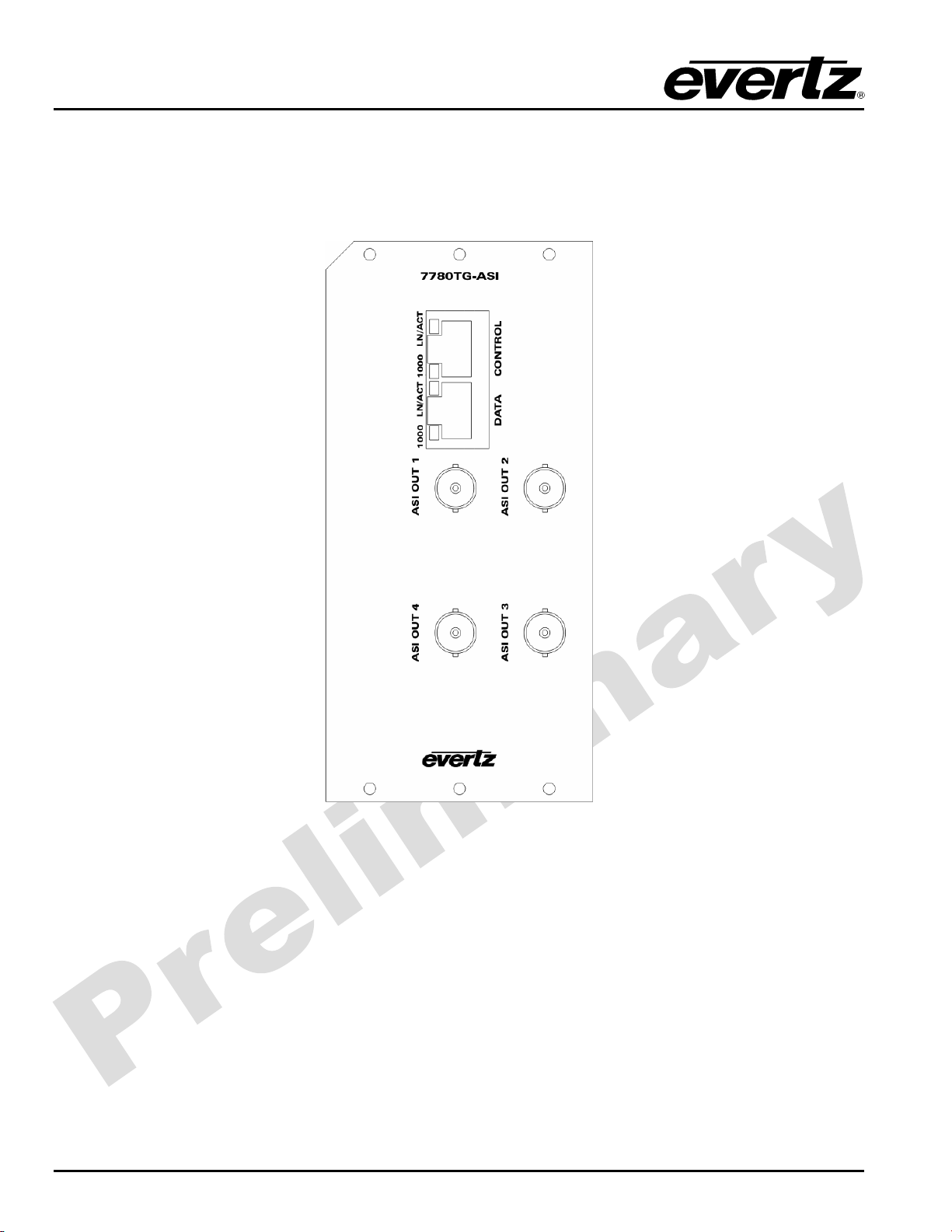
Figure 2-1: 7780TG-ASI Rear Panel.................................................................................................... 2
Figure 2-2: 7700 Chassis..................................................................................................................... 3
Figure 2-3: Compact Flash Card Installed........................................................................................... 3
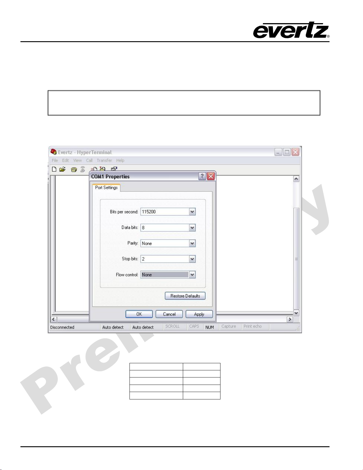
Figure 2-4: COM Port Properties Window ........................................................................................... 4
Figure 2-5: HyperTerminal Main Menu................................................................................................ 5
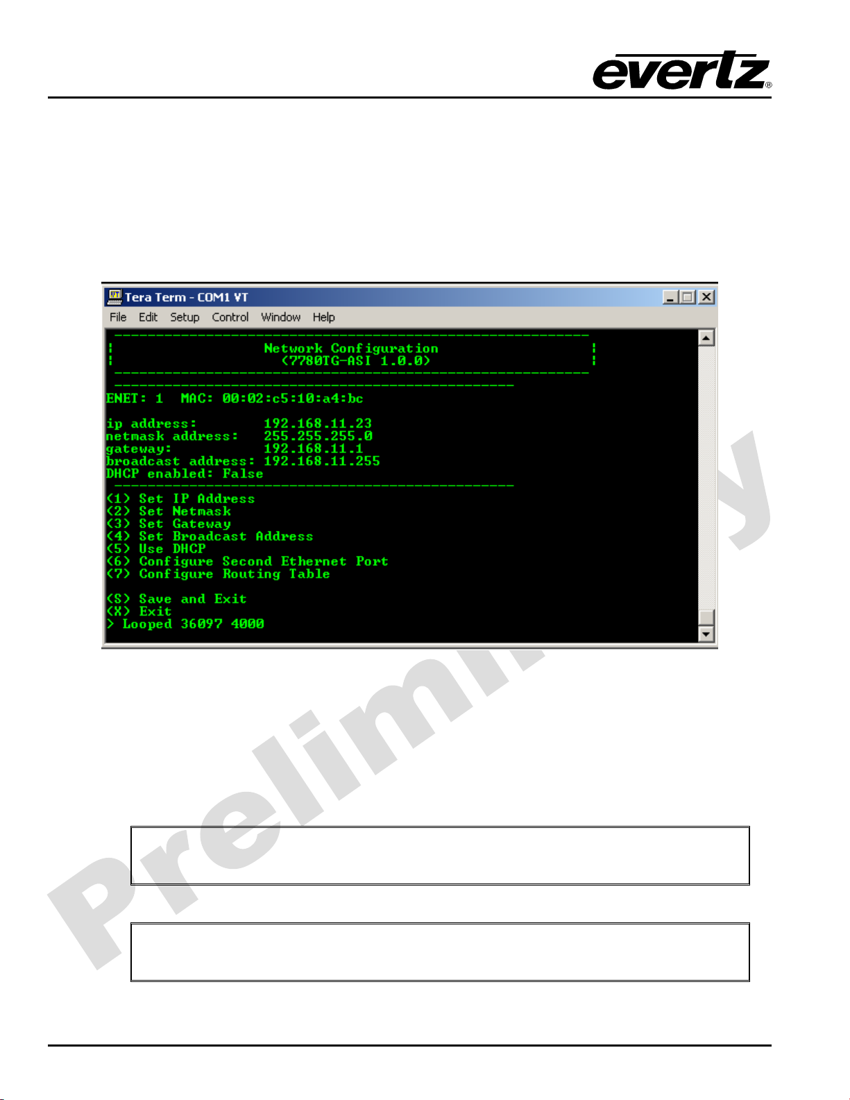
Figure 2-6: Network Configuration Sub-Menu ..................................................................................... 6
Figure 2-7: VistaLINK
®
PRO Hardware Configuration......................................................................... 7
Figure 3-1: VistaLINK
®
PRO File Transfer Tab.................................................................................... 8
Figure 3-2: VistaLINK
®
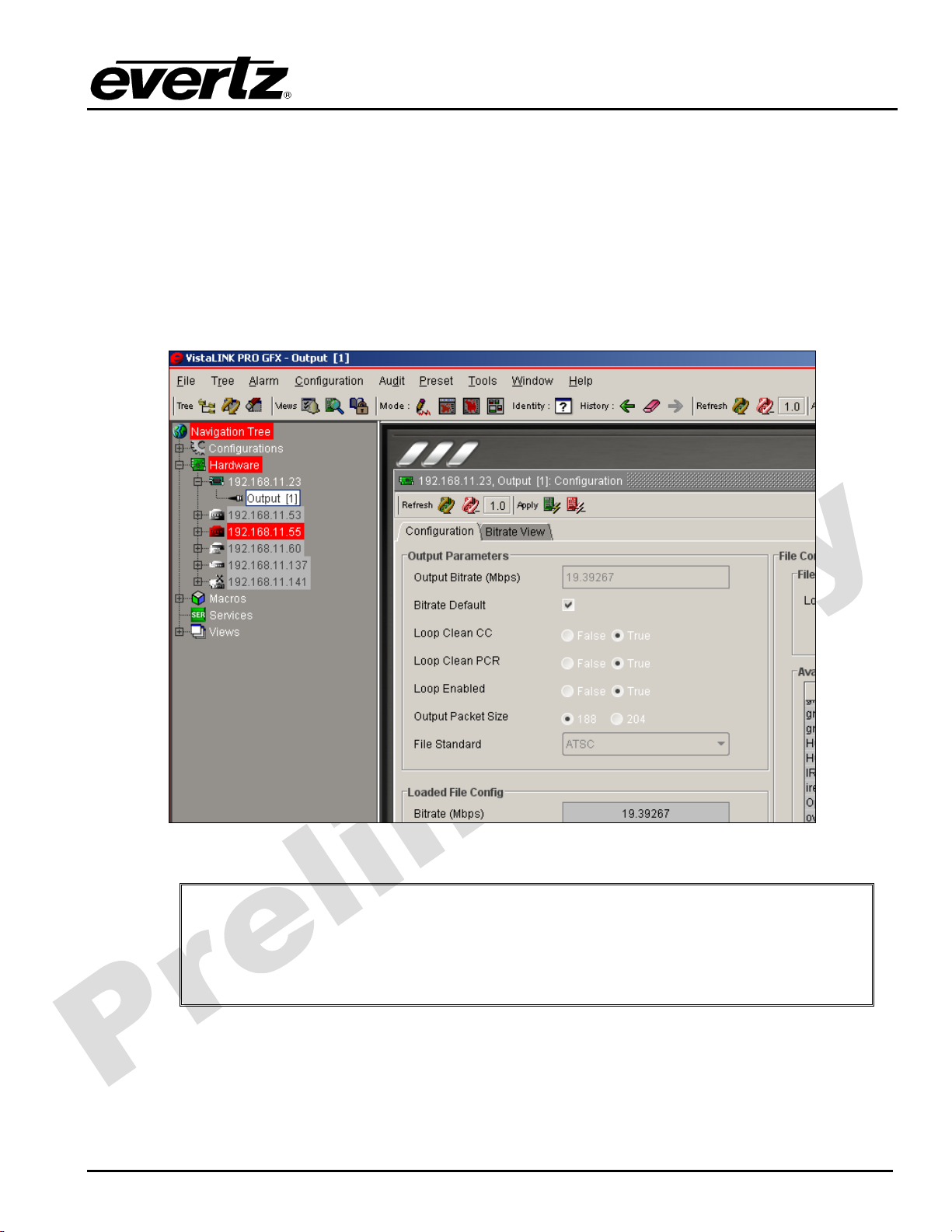
PRO Configuration Tab ................................................................................ 10
Figure 4-1: Formatting the Compact Flash........................................................................................13

7700 MultiFrame Manual
7780TG-ASI ASI Test Signal Generator
Revision 0.1
REVISION HISTORY
REVISION DESCRIPTION DATE
0.1 Preliminary Version Nov 08
Information contained in this manual is believed to be accurate and reliable. However, Evertz assumes no responsibility for the use thereof nor for
the rights of third parties, which may be affected in any way by the use thereof. Any representations in this document concerning performance of
Evertz products are for informational use only and are not warranties of future performance, either expressed or implied. The only warranty offered
by Evertz in relation to this product is the Evertz standard limited warranty, stated in the sales contract or order confirmation form.
Although every attempt has been made to accurately describe the features, installation and operation of this product in this manual, no warranty is
granted nor liability assumed in relation to any errors or omissions unless specifically undertaken in the Evertz sales contract or order confirmation.
Information contained in this manual is periodically updated and changes will be incorporated into subsequent editions. If you encounter an error,
please notify Evertz Customer Service department. Evertz reserves the right, without notice or liability, to make changes in equipment design or
specifications.

7700 MultiFrame Manual
7780TG-ASI ASI Test Signal Generator
Revision 0.1 7780TG-ASI-1
1. OVERVIEW
The 7780TG-ASI Test Signal Generator provides a cost-effective method of generating ASI test signals.
The 7780TG-ASI is ideal for checking signal path integrity, or to determine system performance over
varying cable lengths, or for providing slates for emergency broadcasting. The 7780TG-ASI generates
custom test signals in DVB-ASI transport stream formats.
The 7780TG-ASI can store MPEG-2 TS files on the Flash Card provided with the card. When a file is
played out it is transferred in non-real time to the RAM of the card. The 7780TG-ASI will playout in the real
time of the selected file from the RAM.
Features:
•4 identical ASI outputs
•H.264, MPEG-2 SD and HD wrapped in MPEG-2 transport stream
•Customized bit rates from files default to 210Mbits/s
•8 GB of removable flash storage
•374MB of Playout RAM (2,089,999 MPEG-2 packets)
•Output Bitrate configurable by user
•Load multiple MPEG-2 TS via FTP or directly on Flash
•VistaLINK
®
control
Figure 1-1: 7780TG-ASI Block Diagram

7700 MultiFrame Manual
7780TG-ASI ASI Test Signal Generator
7780TG-ASI-2 Revision 0.1
2. INSTALLATION
The 7780TG-ASI module comes with a companion rear plate that has 4 BNC connectors and 2xIP RJ45
connectors. For information on mounting the rear plate and inserting the module into the frame see the
7700FR chapter section 3.
Figure 2-1: 7780TG-ASI Rear Panel
CONTROL: RJ45 Ethernet port I/O for control via SNMP agent such as VistaLINK
®
PRO.
DATA: Ethernet port I/O. At this time, the DATA port is UNUSED.
OUTPUT: There are 4 BNC connectors that carry serial ASI transport stream outputs. The test signal
output is selected using VistaLINK
®
PRO control.

7700 MultiFrame Manual
7780TG-ASI ASI Test Signal Generator
7780TG-ASI-4 Revision 0.1
Before inserting the front card, connect the serial cable to the board using the rainbow coloured serial
cable provided. Now insert the 7780TG-ASI card into the corresponding front slots ensuring the card lines
up with the slot runners on the bottom and the top of the chassis. Push the card into the slot and make
sure that when it mates with the rear card it has been pushed firmly into a seated position. This can be
confirmed when the connectivity lights for the Ethernet port are illuminated.
"
Do not connect any cables to the rear card until the initial configuration has been
completed (failure to do this could cause unwanted network issues).
Connect the 9-pin d-type end of the serial cable to the serial port of your computer. Open a Terminal
session and configure the port for the following configuration:
Figure 2-4: COM Port Properties Window
Bits per second 115200
Data Bits 8
Parity None
Stop Bits 2
Flow Control None
Click OK to apply these settings and press return. The session should respond with the 7780TG-ASI Main
Menu as shown in Figure 2-5:

7700 MultiFrame Manual
7780TG-ASI ASI Test Signal Generator
Revision 0.1 7780TG-ASI-5
Figure 2-5: HyperTerminal Main Menu
(1) Network Configuration
This sub-menu enables the user to configure the network settings for the card.
(2) SNMP Configuration
This sub-menu enables the user to configure the Simple Network Management Protocol settings. In this
menu you can set or remove the SNMP trap IP address and the SNMP Read and Set community strings.
(3) Setup Transport Stream Receivers
This sub-menu is not used for this product.
(4) Setup Test generator
This sub-menu can be used to configure the 7780TG-ASI. This configuration can also be performed via
VLPro; consequently, the sub-menu for this item will not be covered in this section.
(5) Utilities
This sub-menu contains two utilities. One command is for clearing the memory, and the other for clearing
the flash. In normal operation it should not be necessary to use either of these options.
(6) Engineering/Debug
This menu is for Evertz personnel only. You may be requested to access and execute options within this
menu when seeking technical support from Evertz. Guidance will be given should this be required.
Before it is possible to configure the card via VLPro it is first necessary to configure the initial basic
network settings via the serial cable, this is covered in section 2.1.
2.1. CONFIGURING THE BASIC NETWORK SETTINGS
Select option (1) Network Configuration, the Network Configuration menu will be displayed as shown in
Figure 2-6. If you prefer to use DHCP then you may select option (5) Use DHCP, and then continue from
step 4:

7700 MultiFrame Manual
7780TG-ASI ASI Test Signal Generator
7780TG-ASI-6 Revision 0.1
1. Select option (1) Set IP Address and configure the IP address for the 7780TG-ASI ensuring that
the IP address is not already in use on the network.
2. Now select option (2) Set Netmask from the Network Configuration menu and configure the correct
subnet mask for your network.
3. If required, also configure option (3) Set Gateway.
4. Exit from the Network Configuration menu using (S) Save and Exit, NOT (X) Exit.
Figure 2-6: Network Configuration Sub-Menu
In the Main Menu, select option (2) SNMP Configuration. Then select option (1) Set Trap IP Address from
the SNMP Configuration menu, and enter the IP address of your VLPro Server. Exit using option (S) Save
and Exit. Now, extract the card from the rack, remove the serial cable and re-insert it.
You have now completed the necessary minimum configuration and can connect the cables to the rear
card when ready.
"
Note: The firmware version number is displayed in the menu title.
"
Note: If the unit is in DHCP mode and no DHCP server is found it will take about
3 minutes for the card to time out and boot.

7700 MultiFrame Manual
7780TG-ASI ASI Test Signal Generator
Revision 0.1 7780TG-ASI-7
2.2. CONNECTING TO VLPRO
This chapter assumes that the VLPro server and VLPro client are already configured for your network and
that you have basic knowledge of the VLPro interface. It also assumes that the user or network
administrator has already added the 7780TG-ASI jar file to the server and both the client and server
applications have been restarted.
Open VLPro and click on the refresh tree icon. Expand the hardware tree by clicking on the “+”. Your
7780TG-ASI should appear as a newly listed device with the IP address used to configure the card (in
Step 1 as previously mentioned). It may take up to a minute to appear while the card and switch negotiate
network settings (this can be verified directly on the switch if necessary).
Figure 2-7: VistaLINK
®
PRO Hardware Configuration
"
Note: If after a couple of minutes the card has still not appeared, try selecting
Add Agent from the Tree> Add/Update Agent menu. Enter the IP address used
in the configuration stage earlier and select OK. The card should now be listed
but will remain greyed out for a moment while VLPro communicates with the
card and confirms its configuration.
Please consult your network administrator if you continue to have problems connecting the card with
VLPro. Alternatively, contact Evertz Microsystems Ltd. or your authorized reseller for technical support.

7700 MultiFrame Manual
7780TG-ASI ASI Test Signal Generator
7780TG-ASI-8 Revision 0.1
3. CARD CONFIGURATION
3.1. FILES MANAGEMENT
Right-click the IP address of the 7780TG-ASI in the VLPRO Tree. Select View Configuration. The right
window will display the 7780TG-ASI File management menus as shown in Figure 3-1.
Figure 3-1: VistaLINK
®
PRO File Transfer Tab
This page allows the management of the MPEG-2 transport file on the compact flash. The 7780TG-ASI
ships with an 8GB compact flash that is on the board. All playout files are stored on the compact flash. All
file management from VLPRO is handled via FTP to the card.
•File Transfer: This page will display the list of the files available on the compact flash as well as
the size of each file. Please note that the maximum file size that can be played out
is 374MB. If the file is larger than 512MB the 7780TG-ASI will load and play the first
374MB of the file.
•Delete: The icon is used to remove a file from the Compact Flash. Select a file, click
on the “X” icon and then follow the dialog to remove the file. Click on refresh to
make sure the file has been deleted.

7700 MultiFrame Manual
7780TG-ASI ASI Test Signal Generator
Revision 0.1 7780TG-ASI-9
•Import: The icon shows an arrow pointing to the compact flash. It is used for importing a
file to the Compact Flash from the local PC where VLPRO client is running. When clicking
on this icon, locate the file to import and click the “import” icon. The Card will open an FTP
process in the FTP Process window and will begin transferring the file. Depending on the
size of the file it could take several minutes to import a file. Note that the Compact Flash will
access any type of file so it is up to the user to make sure the uploaded files are MPEG-2
transport streams.
•Export: The icon is used for exporting a file from the Compact Flash to the local PC where
VLPRO client is running. Locate the file to export, click on the “export” button and choose
the location for the file on the local pc running VLPRO. The Card will open an FTP process
in the FTP Process window and will begin transferring the file. Depending on the size of the
file it could take several minutes to export a file.
•Refresh: The icon shows a double circular arrow. It is used for refreshing the view in the list of
files on the compact flash.
"
Note: It is also possible to remove the Compact Flash from the card reader and
manage the files using a compact Flash reader. The files are not encrypted and
straight MPEG-2 Transport streams. Please power the card off before removing or
inserting the Compact Flash. Note that a new Compact Flash has to be formatted
using the 7780TG-ASI to be recognized.
It is recommended to use less than 20 characters for file name and avoid *, /, .in the name.
•Compact Flash Status: This area displays the status of the Compact Flash and provides any
necessary indications regarding the FTP process.
oPresent: When the Compact Flash is not detected, the PRESENT indicator will
be red. When detected, it will be green.
oTotal Space: This represents the total space available on the Compact Flash card.
oSpace Available: This represents the space available for additional files on the Compact
Flash card.
oFTP Process: This window displays the progress of the FTP process when uploading,
downloading, or deleting files. When an error occurs due to an FTP transfer
failure it will be displayed in this window.
"
Please note that depending on the operating system and how the file size is reported,
the file size may not be 100% accurate.

7700 MultiFrame Manual
7780TG-ASI ASI Test Signal Generator
7780TG-ASI-10 Revision 0.1
3.2. PLAYOUT CONFIGURATION
Right-click the ASI Output 1 under the IP address of the 7780TG-ASI in the VLPRO Tree. Select View
Configuration. The right window will display the 7780TG-ASI Configuration and Bitrate View tab menus as
shown in Figure 3-2.
Figure 3-2: VistaLINK
®
PRO Configuration Tab
This tab is for configuring the playout mode and selecting the file to playout.
•File command: This area will display the list of the files available on the compact flash as well as
the size of each file. It allows basic playout control such as load, play, stop and
pause.
oStop: The red square icon is used to stop a playout. Click on this icon to stop the
playout and allow the edit of the output parameters.
oPlay: The green arrow icon is used to start the playout of the loaded file into the
RAM. When clicking this icon, it will initiate the loaded file playout at the start of the
file. It will also disable the editing of the output parameters.

7700 MultiFrame Manual
7780TG-ASI ASI Test Signal Generator
Revision 0.1 7780TG-ASI-11
oPause: The orange double-line icon is used to pause the playback. Clicking on this
icon will stop the playout of the file loaded into the RAM. Selecting the Pause button
again will resume the playout of the file, continuing from the point at which the
playout was paused.
oLoad: The blue triangle icon is used to load a selected file into the RAM. To load a
file into the RAM, select a file from the Available Files list and click on the triangle
icon. Depending on the size of the file it can take several minutes to load a file. A
progress report will be displayed in the status window.
oRefresh: The icon is used for refreshing the view of the Available Files list on the
compact flash.
•File Playing: This area displays the file loaded into the RAM for playout. Note that if the file
size is larger than the 374MB of RAM, it will be truncated and will not play the
complete file.
•Status: This area displays the status of the 7780TG-ASI. The status display includes
playing, loading, stopped, and paused.
•Output Parameters: This area allows the user to change the streams parameters and the
playback settings.
oOutput Bitrate: This displays the output Bitrate of the 7780TG-ASI and allows the user to
modify the Bitrate while not in default Bitrate mode. Note that the Bitrate cannot be
set lower than the default Bitrate. When increasing the output Bitrate, the 7780TG-
ASI will add null packets to match the required Bitrate and restamp the PCR and
PTS to reflect the new rate.
oDefault: The default Bitrate of the file is calculated based on PCR in the file.
oLoop Clean CC: When this option is set to True and when looping is enabled, the
7780TG-ASI will recalculate the Continuity counts to avoid any Continuity Count
errors upon looping. When it is disabled, the 7780TG-ASI will restart the Continuity
count of the original stream after each loop.
oLoop Clean PCR: When this option is set to True and when looping is enabled, the 7780TG-
ASI will recalculate the PCR and PTS/DTS to avoid any PCR and PTS/DTS
discontinuity upon looping. When it is disabled, the 7780TG-ASI will restart the PCR
and PTS/DTS counters of the original stream after each loop.
oLoop Enabled: This option will enable or disable looping. If the user selects False, the file
will play once and then stop.
oOutput Packet Size: The Standard MPEG-2 packets are 188 Bytes long. The 7780TG-
ASI can play 204 byte packets by adding 16 dummy RS (Reed-Solomon) bytes.

7700 MultiFrame Manual
7780TG-ASI ASI Test Signal Generator
7780TG-ASI-12 Revision 0.1
oFile Standard: The user can choose between MPEG-2, DVB, and ATSC standard. This
field only affects what context is used to interpret the transport stream. This
is only used to display the proper table under the Bitrate view and does not
affect the playout.
•Loaded File Config: Displays the key elements of the file loaded in the RAM.
oBitrate (Mbps): This field displays (in Mbps) the nominal Bitrate of the file calculated using
PCR in the file.
oUsed Bitrate (Mbps): This field displays (in Mbps) the nominal average used bitrate of
the file. Used Bitrate is defined by Total Bitrate minus null packets.
oNumber of Programs: This field displays the number of programs declared in the PAT. Note
that if a program is not present, this field may display inaccurate information
if the PAT and the actual content of the file are not the same.
oPacket Size: This field displays the nominal packet size in the file. It can be 188 or 204
bytes per packets.
oDuration (s): This field displays the duration of the file calculated from the Bitrate (derived
from PCR) and the number of packets loaded into the Compact Flash. The
time is provided in seconds.

7700 MultiFrame Manual
7780TG-ASI ASI Test Signal Generator
Revision 0.1 7780TG-ASI-13
4. COMPACT FLASH MAINTENANCE
The 7780TG-ASI comes with an 8G Compact Flash. It has MPEG-2 TS files built in. If you want to replace
the flash or add your own flash, make sure it is at least an Ultra II Compact Flash (for speed).
"
You also need to format the new flash inside the 7780TG-ASI for the file system to
show.
4.1. FORMATTING THE COMPACT FLASH
In order to format a Compact Flash, insert the new flash on the 7780TG-ASI and connect to the serial port
menu of the card (See section 2).
Select menu (5) for Utilities. And then, select option (3) Format Compact Flash as shown in Figure 4-1.
"
Please note that all files will be erased from the Compact Flash.
Figure 4-1: Formatting the Compact Flash

7700 MultiFrame Manual
7780TG-ASI ASI Test Signal Generator
7780TG-ASI-14 Revision 0.1
5. SPECIFICATIONS
5.1. SERIAL TRANSPORT STREAM OUTPUTS
Standards: DVB ASI (1 to 210 Mb/s)
Number of Outputs: 4 (Identical)
Connector: BNC per IEC 169-8
Signal Level: 800mV nominal
DC Offset: 0V ±0.5V
Rise and Fall Time: 740ps nominal
Overshoot: <10% of amplitude
Return Loss: > 15 dB up to 270 Mb/s
Wide Band Jitter: < 0.2 UI
5.2. ELECTRICAL
Voltage: + 12V DC
Power: 45 Watts
EMI/RFI: Complies with FCC Part 15, class A and EU EMC directive
5.3. PHYSICAL
7700 or 7800 frame mounting:
Number of slots: 3

7700 MultiFrame Manual
7780TG-ASI ASI Test Signal Generator
Revision 0.1 7780TG-ASI-15
6. CARD EDGE CONTROLS
The 7780TG-ASI card edge simply provides information about the version number at this time.
For control and monitoring please use VistaLINK
®

7700 MultiFrame Manual
7780TG-ASI ASI Test Signal Generator
7780TG-ASI-16 Revision 0.1
This page left intentionally blank
Other manuals for 7700 Series
127
This manual suits for next models
1
Table of contents
Other evertz Portable Generator manuals
Popular Portable Generator manuals by other brands

Chicago Electric
Chicago Electric 91523 operating instructions

Viessmann
Viessmann Vitobloc 200 EM-20/39 operating instructions

Harvard Bioscience
Harvard Bioscience BTX ECM 2001+ quick start guide

Ritelite
Ritelite RITE-POWER 3850 Operator's manual

Elettrotest
Elettrotest RPS user manual

Technix
Technix SR10OKV-5KW Operator's manual