7700 MultiFrame Manual
7751SRG-HD HD-SDI Tri-Level Sync Generator
Page - 6 Revision 1.5.2
DIP Switch Output Genlock
# 1 2 3 4 5 1 2 3 4 Type Lock Phased
Outputs
1 Off Off Off Off Off 1080i/60 1080p/24sF 625i/48 6Hz Pulse NTSC Clock ---
2 On Off Off Off Off 1080i/59.94 1080p/23.98sF 625i/47.96 6Hz Pulse NTSC Phase 1
3 Off On Off Off Off 1080i/50 1080p/24sF 625i/48 1Hz Pulse PAL Phase 1
4 On On Off Off Off 1080i/50 720p/50 625i/50 625i/50 PAL Phase 1,2,3,4
5 Off Off On Off Off 1080p/30 1080p/24sF 625i/48 6Hz Pulse NTSC Clock ---
6 On Off On Off Off 1080p/29.97 1080p/23.98sF 625i/47.96 6Hz Pulse NTSC Phase 1
7 Off On On Off Off 1080p/25 1080p/24sF 625i/48 1Hz Pulse PAL Phase 1
8 On On On Off Off Reserved Reserved Reserved Reserved --- --- ---
9 Off Off Off On Off 1080p/24 1080p/24sF 625i/48 625i/48 NTSC Clock ---
10 On Off Off On Off 1080p/23.98 1080p/23.98sF 625i/47.96 625i/47.96 NTSC Clock ---
11 Off On Off On Off 1080p/24sF 1080p/24sF 625i/48 625i/48 NTSC Clock ---
12 On On Off On Off 1080p/23.98sF 1080p/23.98sF 625i/47.96 625i/47.96 NTSC Clock ---
13 Off Off On On Off 720p/60 1080p/24sF 625i/48 6Hz Pulse NTSC Clock ---
14 On Off On On Off 720p/59.94 1080p/23.98sF 625i/47.96 6Hz Pulse NTSC Phase 1
15 Off On On On Off 1035i/60 1080p/24sF 625i/48 6Hz Pulse NTSC Clock ---
16 On On On On Off 1035i/59.94 1080p/23.98sF 625i/47.96 6Hz Pulse NTSC Phase 1
17 Off Off Off Off On 1080i/60 720p/60 525i/59.94 525i/59.94 NTSC Clock ---
18 On Off Off Off On 1080i/59.94 720p/59.94 525i/59.94 525i/59.94 NTSC Phase 1,2,3,4
19 Off On Off Off On 60 V drive 1080p/24sF 625i/48 6 Hz Pulse NTSC Clock ---
20 On On Off Off On 59.94 V drive 1080p/23.98sF 625i/47.96 6 Hz Pulse NTSC Phase 1
21 Off Off On Off On 1080p/24 1080p/24sF 625i/48 625i/48 PAL Phase 1
22 On Off On Off On 1080i/59.94 1080p/23.98sF 625i/50 625i/50 NTSC Clock
23 Off On On Off On 1080i/50 1080p/24sF 525i/59.94 525i/59.94 PAL Clock
24 On On On Off On Reserved Reserved Reserved Reserved --- --- ---
25 Off Off Off On On 1980i/30 1650i/38.30 625i/50 625i/50 PAL Clock
26 On Off Off On On 1980i/29.97 1650i/38.26 525i/59.94 525i/59.94 NTSC Clock
27 Off On Off On On 1080i/59.94 1080p/23.98sF 525i/59.94 6 Hz Pulse NTSC Phase 1
28 On On Off On On 1080i/59.94 1080p/23.98sF 525i/47.96 6 Hz Pulse NTSC Phase 1
29 Off Off On On ON 1080p/25 1080i/50 625i/50 625i/50 PAL Phase 1,2,3,4
Table 5-2: Sync Output Selection Switch Settings
‡Note 1: sync outputs for High Speed Dual Link 2K Data Transfers
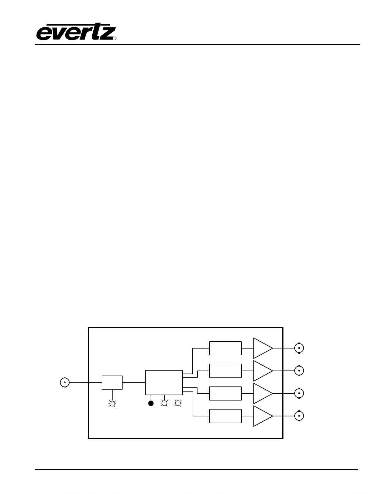
5.2. SELECTING THE GENLOCK REFERENCE
The 7751SRG-HD will free run on its internal crystal oscillator or be referenced to a genlock signal applied
to the GENLOCK input. The genlock signal is a standard definition colour black video or 0.3 V bi-level
sync. DIP switch 6 selects if the 7751SRG-HD will free run or be referenced to the genlock Reference
video as shown in Table 5-3.
DIP 6 FUNCTION DESCRIPTION
Off Free Run
(default) The 7751SRG-HD will free run on its internal crystal oscillator.
On Genlock The 7751SRG-HD sync outputs will be phase locked, or clock
locked to a Standard Definition colour black video or bi-level sync
signal as shown in Table 5-2.
Table 5-3: Genlock Reference Switch Settings
‡
‡