Everwell FCAC Series User manual
FCAC SERIES
FLOOR & CEILING UNIT
ON-OFF
Service Manual
R410A 60Hz EER 2.36 Series Service Manual General Information
Part 1 General Information ........................................................ 2
Part 2 Floor&Ceiling Type ......................................................... 8
Content
Part 3 Installation ........................................................................ 28
Part 4 Controller ......................................................................... 41
1
1
01
05
17
30

R410A 60Hz EER 2.36 Series Service Manual
2. Model Names of Indoor/Outdoor Units
2.1 Indoor units
Model name Dimension (W×H×D) (mm) Net/Gross weight (kg) Power supply
Floor & Ceiling
CUAi-24CR1 1050×235×675 26.5/31
208~230V/1Ph/60Hz
CUAi-36CR1 1250×235×675 32/37
208~230V/1Ph/60Hz
CUAi-60CR1 1670×235×675 40/46
208~230V/1Ph/60Hz
2
FCAC-24
FCAC-36
FCAC-60
R410A 60Hz EER 2.36 Series Service Manual
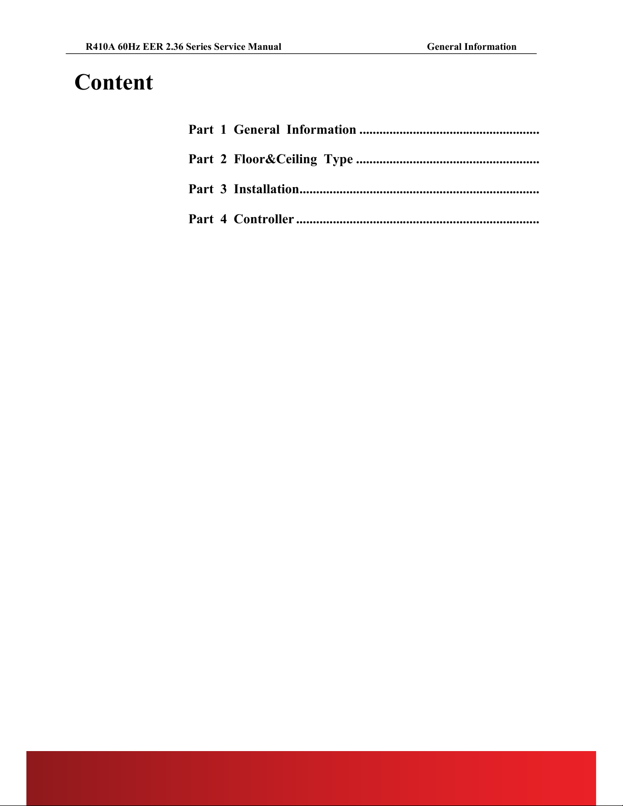
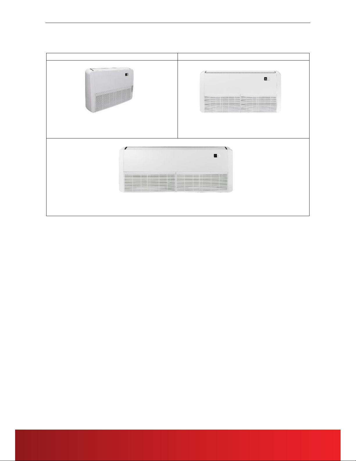
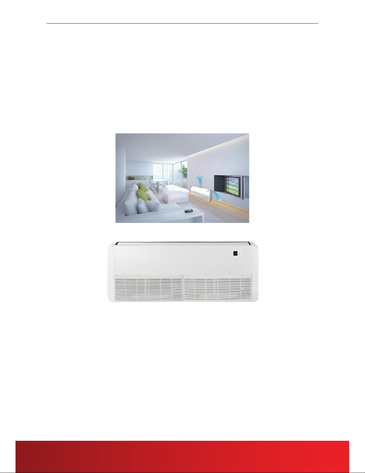
3. External Appearance
3.1 Indoor Units
Floor & Ceiling
24K
36K
60K
3

R410A 60Hz EER 2.36 Series Service Manual
4. Features
4.1 High quality coils
The coil is constructed of advanced inner grooved copper tube and aluminum fins.
4.2 Low operation sound level:
(1) Well-known stable and quiet running fan motor.
(2) Well-known compressor, Sanyo & GMCC & Highly.
(3) Compact design: Smaller dimension and larger stuffing capacity.
(4) Universal outdoor unit design
(5) Compact size design;Slim body, less installation space
(6) Metal casing, more durable
(7) Centrifugal fan, supplying strong air flow(Max 15-meter air flow distance)
(8) 3D air flow, supply cold air to each corner
(9) Bigger screen and bigger buttons
(10) New air flow system with incline evaporator, having a large heat-exchange area in limited space
Suction structure, faster heat exchange
4

R410A 60Hz EER 2.36 Series Service Manual
Part 2
Floor & Ceiling Type
1. Features .............................................................................................................................. 9
2. Specifications ................................................................................................................... 10
3. Dimensions....................................................................................................................... 11
4. Service Space ................................................................................................................... 11
5. Wiring Diagrams .............................................................................................................. 12
6. Electric Characteristics .................................................................................................... 12
7. Sound Levels .................................................................................................................... 13
8. Accessories ....................................................................................................................................... 13
9. The Specification of Power ........................................................................................................... 13
10. Field Wiring ................................................................................................................... 14
11. Explosive View .............................................................................................................. 14
12. Troubleshooting ............................................................................................................. 20
5
R410A 60Hz EER 2.36 Series Service Manual
1. Features
1.1 Flexible installation
Ceiling suspended and floor standing.
1.2 Auto-swing function
Built-in two louver motor, vertical and horizontal air-flow adjustment.
1.3 LED display is optional, in the middle or on the right side.
It is more intuitive and simple, and error code can be shown in the display.
1.4 New upper and lower buckle type wheel case.
The upper wheel case can be removed alone, which is convenient adjust the wheel motor.
6
R410A 60Hz EER 2.36 Series Service Manual
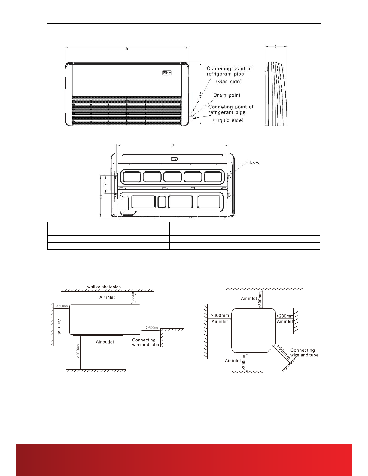
3. Dimensions
Model(kBtu/h)
A(mm)
B(mm)
C(mm)
D(mm)
E(mm)
F(mm)
24
1050
675
235
933
440
188
36
1250
675
235
1185
440
188
60
1670
675
235
1553
440
188
4. Service Space
Ensure enough space required for installation and maintenance.
There is enough space for installation and maintenance. The ceiling is horizontal, and its structure can endure the
weight of the indoor unit. The outlet and the inlet are not impeded, and the influence of external air is the least. The
air flow can reach throughout the room. The connecting pipe and drainpipe could be extracted out easily.
7
R410A 60Hz EER 2.36 Series Service Manual
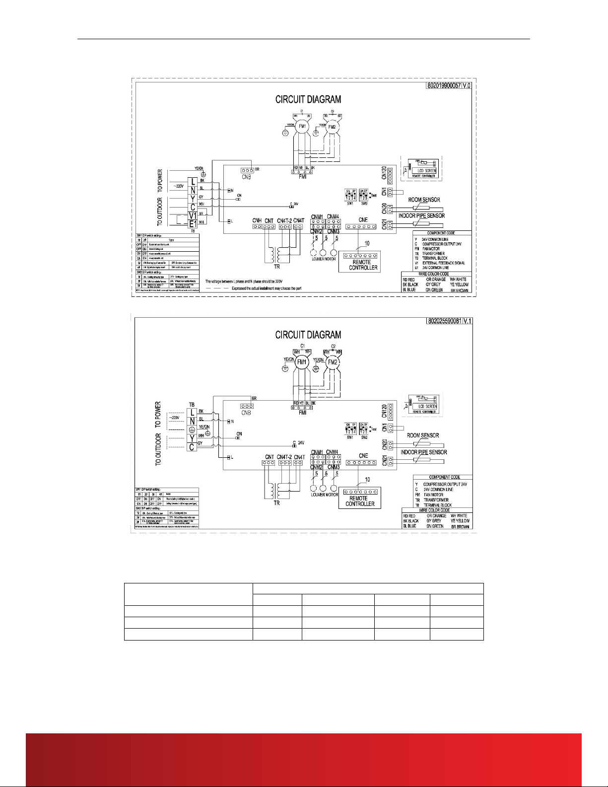
5. Wiring Diagrams
FCAC-24 FCAC-60
6. Electric Characteristics
Model
Indoor Units
Hz
Voltage
Min.
Max.
60
230V
198V
254V
60
230V
198V
254V
60
230V
198V
254V
FCAC-36
FCAC-24
FCAC-36
FCAC-60
8

R410A 60Hz EER 2.36 Series Service Manual
7. Sound Levels
1 m
0.8 m
1 m
1.5 m
Microphone
Microphone
Model
Noise level dB(A)
High
Medium
Low
50
48
45
FCAC-36
57
54
51
FCAC-60
57
54
51
8. Accessories
Name
Shape
Quantity
1.blank self-sealing bag
2
2.Service Manual
/
1
3.insulating pipe 30× 48×135
2
4.insulating pipe 40× 56×175
2
5.drain-pipe
1
6. Remote controller
1
7. Dry batteries
2
8.Instulation assy
/
1
9. The Specification of Power
Cooling only
Type
CUAi-24CR1
CUAi-36CR1
CUAi-60CR1
Indoor unit
Phase
1-phase
1-phase
1-phase
Frequency and Voltage
60Hz,220V
60Hz,220V
60Hz,220V
Power Wiring(mm
2
)
1.0
1.0
1.0
Ground Wiring(mm
2
)
1.0
1.0
1.0
Signal Wiring(mm2)
0.75
0.75
0.75
FCAC-24
9
FCAC-60
FCAC-36
FCAC-24

R410A 60Hz EER 2.36 Series Service Manual
10. Field Wiring
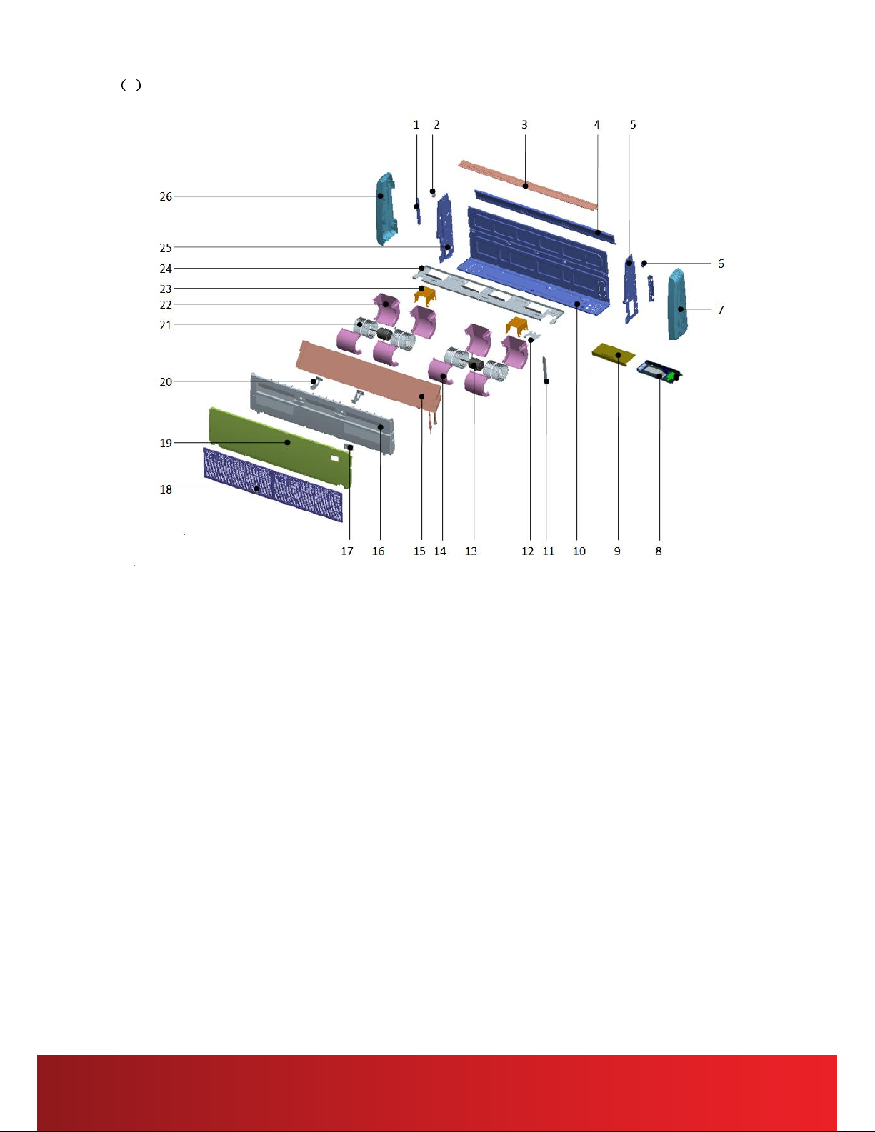
11. Explosive View
1FCAC-24
FCAC-24 FCAC-36 FCAC-60
10

R410A 60Hz EER 2.36 Series Service Manual
No. Part Name Quantity No. Part Name Quantity
1
Chassis foam assembly
1 13.2
Display film
1
2
Rear cover
1 13.3 Display board mounting box 1
3
Chassis assembly
1 14
Air inlet grille
1
4
Indoor PCB assembly
1 15
Top Cover assembly
1
4.1
E-part box
1 16
Supporting board
1
4.2
Indoor PCB
1 17.1
Drip tray foam
1
4.3
Fan capacitor
1 17.2
Louver connecting rod fixed structure class1
1
4.4
Transformer
1 17.3
Louver connecting rod fixed structure class2
1
4.5
Temperature sensors indoor )
1 17.4
Driving lever for louver
1
4.6
Terminal
1 17.5
Louver holder
1
5
E-part box cover
1 17.6
Guard vane
9
6
Left cover
1 18
Right separating board
1
7
Hoisting pate
2 19
Right cover
1
8
Lelf separating board
1 20
Evaporator component
1
9 Weld assembly for intermediate
transverse girder
1 20.1
Evaporator assembly
1
10
Pipe clamp
1 20.2
Evaporator output tube assembly
1
11.1
Centrifugal fan blade
2 20.3 Evaporator input tube assembly 1
11.2
Upper volute
2 20.4
Under the right mounting plate of the
evaporator
1
11.3
Lower volute
2 20.5
Under the left mounting plate of the
evaporator 1
12.1
The motor bracket
1 20.6
Upper the right mounting plate of the
evaporator
1
12.2
Motor shaft sleeve right gland
1 20.7
Upper the left mounting plate of the
evaporator
1
12.3
Motor shaft sleeve left gland
1 21
Step motor
1
12.4
Motor separating board
1 22
Horizontal louver assembly
1
12.5
Indoor fan motor
1 23
Step motor
1
13
Display panel assembly
1 24
Air guide bracke
1
13.1
Display panel components
1
11

R410A 60Hz EER 2.36 Series Service Manual
2FCAC-36
12

R410A 60Hz EER 2.36 Series Service Manual
No. Part Name Quantity No. Part Name Quantity
1 Left cover 1 18.2 Temperature Sensor 1
2 Install lifting ears 2 18.3 Under the right mounting plate of the evaporator 1
3 Stepper motor 1 18.4 Under the left mounting plate of the evaporator 1
4 Left panel assembly 1 18.5 Upper the right mounting plate of the evaporator 1
5 Air guide assembly 1 18.6 Upper the left mounting plate of the evaporator 1
6 Rear Cover 1 19 Display panel components 1
7 Right panel assembly 1 19.1 Digital Tube 1
8 Stepper motor 1 19.2 Show mask 1
9 Right cover 1 19.3 Display board mounting box 1
10 Electro Control Box assembly 1 20 Back style grille assembly 2
10.1 Electro Control Board 1 20.1 Back style grille 2
10.2 Electro Control Box 1 20.2 Dust filter 2
10.3 Temperature Sensor 1 20.3 Grille buckle 4
10.4 Terminal 1 20.4 Grille screw cover 6
10.5 Short circuit Cable 1 21 Top cover parts 1
10.6 PC board isolation column 1 22 Drip tray assembly 1
10.7 Transformer 1 22.1 Drip tray foam 1
10.8 Fan Capacitor 1 22.2 Horizontal swing leaf mounting 1 1
10.9 Light board cable group 1 22.3 Horizontal swing leaf mounting 2 1
11 Electro Control Box Cover 1 22.4 Horizontal swing leaf active rod 1
12 Support bar 1 22.5 Horizontal swing leaf connecting rod 1 1
13 Piping plate 1 22.6 Wind guide blade 10
14 Motor bracket 1 22.7 Stepper motor 1
15 Centrifugal fan blade 2 23 Air guide bracket 1
16 Upper volute 3 24 Motor hoard 1
17 Fan Motor 1 25 Coupling 1
18 Evaporator component 1 26 Connecting shaft 1
18.1 Evaporator pre-welded components 1 27 Motor support assembly 1
18.1.1 Evaporator assembly 1 28 Lower volute 3
18.1.2 Evaporator output tube assembly 1 29 Middle beam welding assembly 1
18.1.3 Evaporator input tube assembly 1 30 Base assy 1
13
R410A 60Hz EER 2.36 Series Service Manual
3FCAC-60
14

R410A 60Hz EER 2.36 Series Service Manual
Part Name Quantity No. Part Name Quantity
1 Right mounting plate of evaporator 1 15.7 Evaporator left lower mounting plate 1
2 Horizontal step motor 1 16 Water tray assy 1
3 Wind guide assembly 1 16.1 Water tray foam assembly 1
4 Rear cover with cotton 1 16.2 Horizontal swing leaf mount 1 1
5
Right side board assembly
1 16.3 Horizontal swing leaf mount 2 1
6 Horizontal step motor 1 16.4 Horizontal swing leaf active rod 1
7
Right cover
1 16.5 Horizontal swing leaf connecting rod 1 1
8 Indoor PCB assembly 1 16.6 Horizontal swing leaf connecting rod 2 1
8.1 E-part box 1 16.7 Wind guide blade 1
8.2 Indoor PCB 1 16.8 Vertical stepper motor 1
8.3 Terminal 1 17 Display panel assembly 1
8.4 Transformer 1 17.2 Show mask 1
8.5 Blade fan capacitor 2 17.3 Display board mounting box 1
9 Electric box cover 1 18 Back style assembly 2
10 Chassis assembly 1 18.1 Back style 2
11 Support bar 1 18.2 Filter 2
12 Pipe plate 1 18.3 Grille buckle 6
13 Indoor fan motor 2 18.4 Grille screw cover 6
14 Upper volute 4 19 Top cover assy 1
15
Evaporator assy
1 20 Wind guide bracket 2
15.1 Evaporator assembly 1 21 Centrifugal fan blade 4
15.2 Evaporator return header assembly 1 22 Lower volute 4
15.3 Evaporator splitter capillary assembly 1 23 Motor bracket 2
15.4 Evaporator right mounting plate 1 24 Middle beam welding assembly 1
15.5 Evaporator left mounting plate 1 25
Left side board aessembly
1
15.6 Evaporator right lower mounting plate 1 26
Left cover
1
15

R410A 60Hz EER 2.36 Series Service Manual
12. Troubleshooting
Fault Code Table
4LED Faults Digital display Failure description
Timer light flashing E2 Ambient temperature sensor (T1) failure
Running light flashing E3 Evaporator pipe temperature sensor (T2) failure
Defrost light flashing E5 Condenser pipe temperature sensor (T3) failure
Warning light flashing F5 Water fulfilled protection
Running light,
defrost light flashing
E1 Indoor unit and wire controller communication failure
Running light,
timer light flashing
P6 Indoor unit EEPROM failure
Defrost light,
timer light flashing
F0
Indoor fan stall protection
(DC Motor)
Defrost light,
warning light flashing
F2
Outdoor protection
(220V Communication control)
F7 Outdoor unit over-current protection (Reserve)
Timer light,
warning light flashing
E0
Indoor unit and outdoor unit communication failure
(RS485 Communication control)
Running light, defrost light, timer light
flashing
F3
High pressure protection
(RS485 Communication control)
Defrost light, timer light, warning light
flashing
F4
Low pressure protection
(RS485 Communication control)
Running light, timer light, warning
light flashing
F8
Outdoor unit exhaust temperature over-high protection
(RS485 Communication control)
Running light, defrost light, timer light,
warning light flashing
F9
Three-phase electricity phase sequence failure
(RS485 Communication control)
Note: the flashing frequency for all above indication lights is 1HZ
16

R410A 60Hz EER 2.36 Series Service Manual
Part 4
Installation
1. Precaution on Installation .................................................................... 29
2. Vacuum Dry and Leakage Checking ................................................... 30
3. Additional Refrigerant Charge ............................................................ 31
4. Water Drainage .................................................................................... 32
5. Insulation Work ................................................................................... 35
6. Test Operation ..................................................................................... 37
7. Install of indoor units ........................................................................... 38
17
R410A 60Hz EER 2.36 Series Service Manual
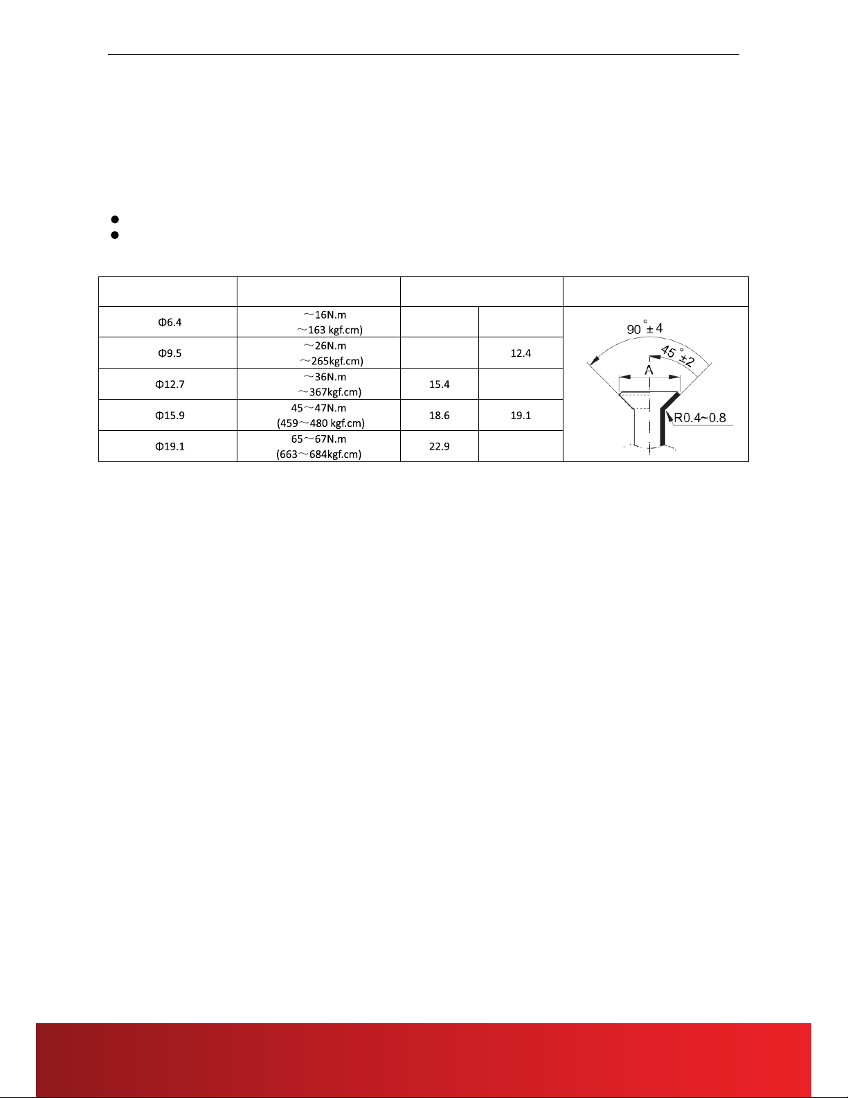
1.Precaution on Installation
1.1. Measure the necessary length of the connecting pipe, and make it by the following way.
a. Connect the indoor unit at first, then the outdoor unit.
Bend the tubing in proper way. Do not harm them.
CAUTIONS:
Daub the surfaces of the flare pipe and the joint nuts with frozen oil, and wrench it for 3~4 rounds
With hands before fasten the flare nuts.
Be sure to use two wrenches simultaneously when you connect or disconnect the pipes.
Pipe gauge Tightening torque
Flare dimension A
Min (mm) Max
Flare shape
15
(153 8.3 8.7
25
(255 12.0
35
(357 15.8
23.3
b. The stop value of the outdoor unit should be closed absolutely (as original state). Every time you
connect it, first loosen the nuts at the part of stop value, then connect the flare pipe immediately (in
5 minutes). If the nuts have been loosened for a long time, dusts and other impurities may enter the
pipe system and may cause malfunction later. So please expel the air out of the pipe with refrigerant
before connection.
c. Expel the air after connecting the refrigerant pipe with the indoor unit and the outdoor unit. Then
fasten the nuts at the repair-points.
1.2. Locate The Pipe
a. Drill a hole in the wall (suitable just for the size of the wall conduit), then set on the fittings such as
the wall conduit and its cover.
b. Bind the connecting pipe and the cables together tightly with binding tapes. Do not let air in, which
will cause water leakage by condensation.
c. Pass the bound connecting pipe through the wall conduit from outside. Be careful of the pipe
allocation to do no damage to the tubing.
1.3. Connect the pipes.
1.4. Then, open the stem of stop values of the outdoor unit to make the refrigerant pipe connecting the
indoor unit with the outdoor unit in fluent flow.
1.5. Be sure of no leakage by checking it with leak detector or soap water.
1.6. Cover the joint of the connecting pipe to the indoor unit with the soundproof / insulating sheath
(fittings), and bind it well with the tapes to prevent leakage.
18
R410A 60Hz EER 2.36 Series Service Manual
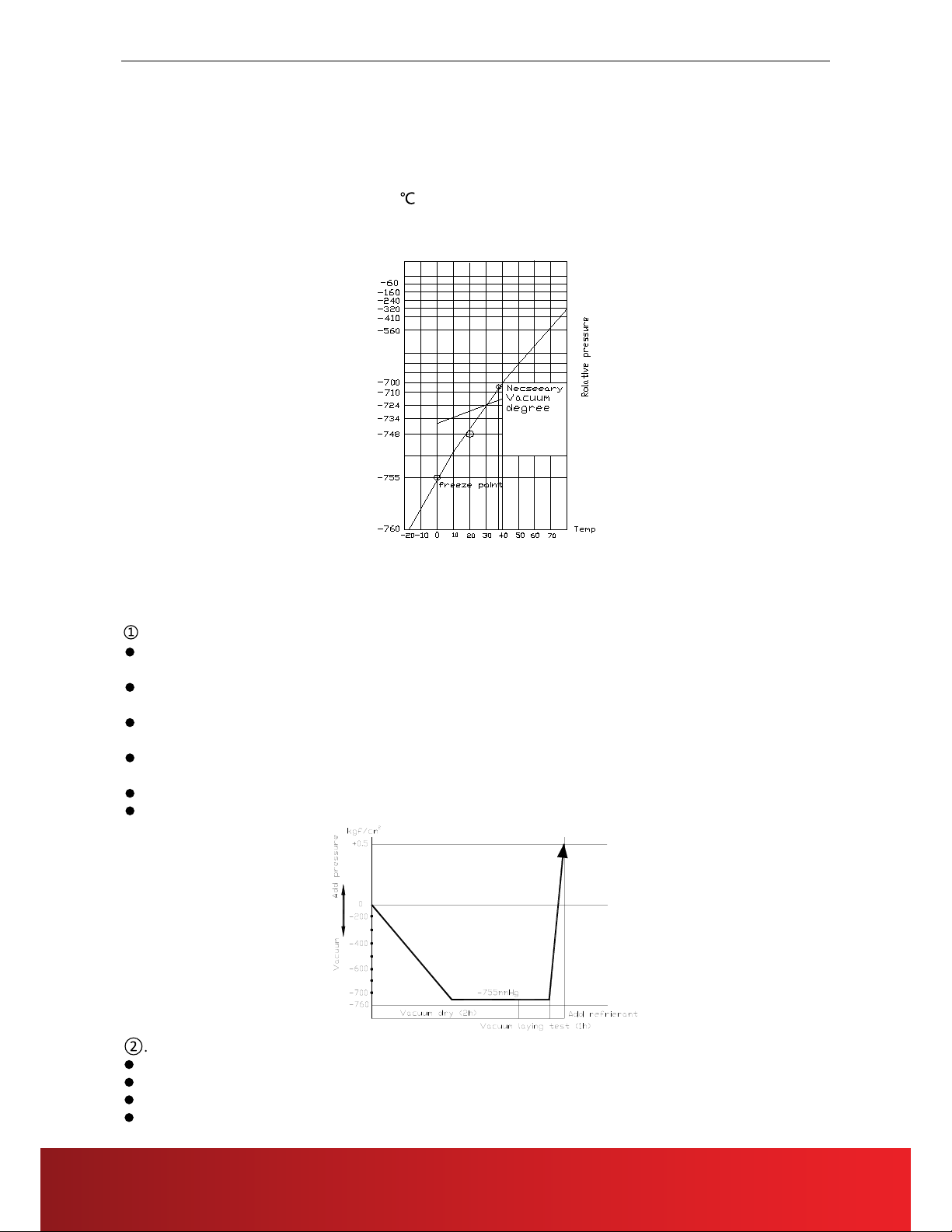
2.Vacuum Dry and Leakage Checking
2.1 Vacuum Dry: use vacuum pump to change the moisture (liquid) into steam (gas) in the pipe and
discharge it out of the pipe to make the pipe dry. Under one atmospheric pressure, the boiling point
of water(steam temperature) is 100 . Use vacuum pump to make the pressure in the pipe near
vacuum state, the boiling point of water falls relatively. When it falls under outdoor temperature, the
moisture in the pipe will be vaporized.
2.2 Vacuum dry procedure
There are two methods of vacuum dry due to different construction environment: common vacuum dry,
special vacuum dry.
. Common vacuum dry procedure
Vacuum dry (for the first time)---connect the all-purpose detector to the inlet of liquid pipe and gas
pipe, and run the vacuum pump more than two hours (the vacuum pump should be below -755mmHg)
If the pump can’t achieve below -755mmHg after pumping 2 hours, moisture or leakage point will still
exist in the pipe. At this time, it should be pumped 1 hour more.
If the pump can’t achieve -755mmHg after pumping 3 hours, please check if there are some leakage
points.
Vacuum placement test: place 1 hour when it achieves -755mmHg, pass if the vacuum watch shows
no rising. If it rises, it shows there’s moisture or leakage point.
Vacuuming from liquid pipe and gas pipe at the same time.
Sketch map of common vacuum dry procedure.
Special vacuum dry procedure
This vacuum dry method is used in the following conditions:
There’s moisture when flushing the refrigerant pipe.
Rainwater may enter into the pipe.
Vacuum dry for the first time ······ 2h pumping
19
This manual suits for next models
3
Table of contents
Other Everwell Air Conditioner manuals


Popular Air Conditioner manuals by other brands


dirna Bergstrom
dirna Bergstrom COMPACT N&D Mounting instructions

Olimpia splendid
Olimpia splendid OS-CEBSH24EI Instructions for installation, use and maintenance

Samsung
Samsung AS09F Series installation manual

Termo
Termo 564500 instruction manual

Mitsubishi Electric
Mitsubishi Electric MXZ-2C20NAHZ installation guide

Admiral
Admiral AW-10CM1FLU use and care manual