Everwell MRL0923E User manual

Models
CONTENTS
1. Important Notice
2. Product Dimensions
3. Refrigeration cycle diagram
4. Operation details
5. Wiring diagram
6. Explosion view and parts
7. Precaution
8. Names of parts
9. Installation manual
10. Trouble shooting
MRL0923E/MRL0923C
MRL1213E/MRL1213C
MRL1223E/MRL1223C
MRL1823E/MRL1823C
MRL2423E/MRL2423C
SERVICE MANUAL

Air Conditioner Service Manual
1. IMPORTANT NOTICE
This service manual is intended for use by individuals possessing adequate
backgrounds of electrical, electronic and mechanical experience. Any
attempt to repair the appliance may result in personal injury and property
damage. The manufacturer or seller cannot be responsible for the
interpretation of this information, nor can it assume any liability in
connection with its use.
The information, specifications and parameters are subject to change due
to
technical modification or improvement without any prior notice. The
accurate specifications are presented on the nameplate label.
How to order spare parts
To have your order filled promptly and correctly, please furnish the
following information:
6
Model No. with Indoor or Outdoor
7
Part No. in the Explosion View
8
Part Name
9
The quantity you ordered
1
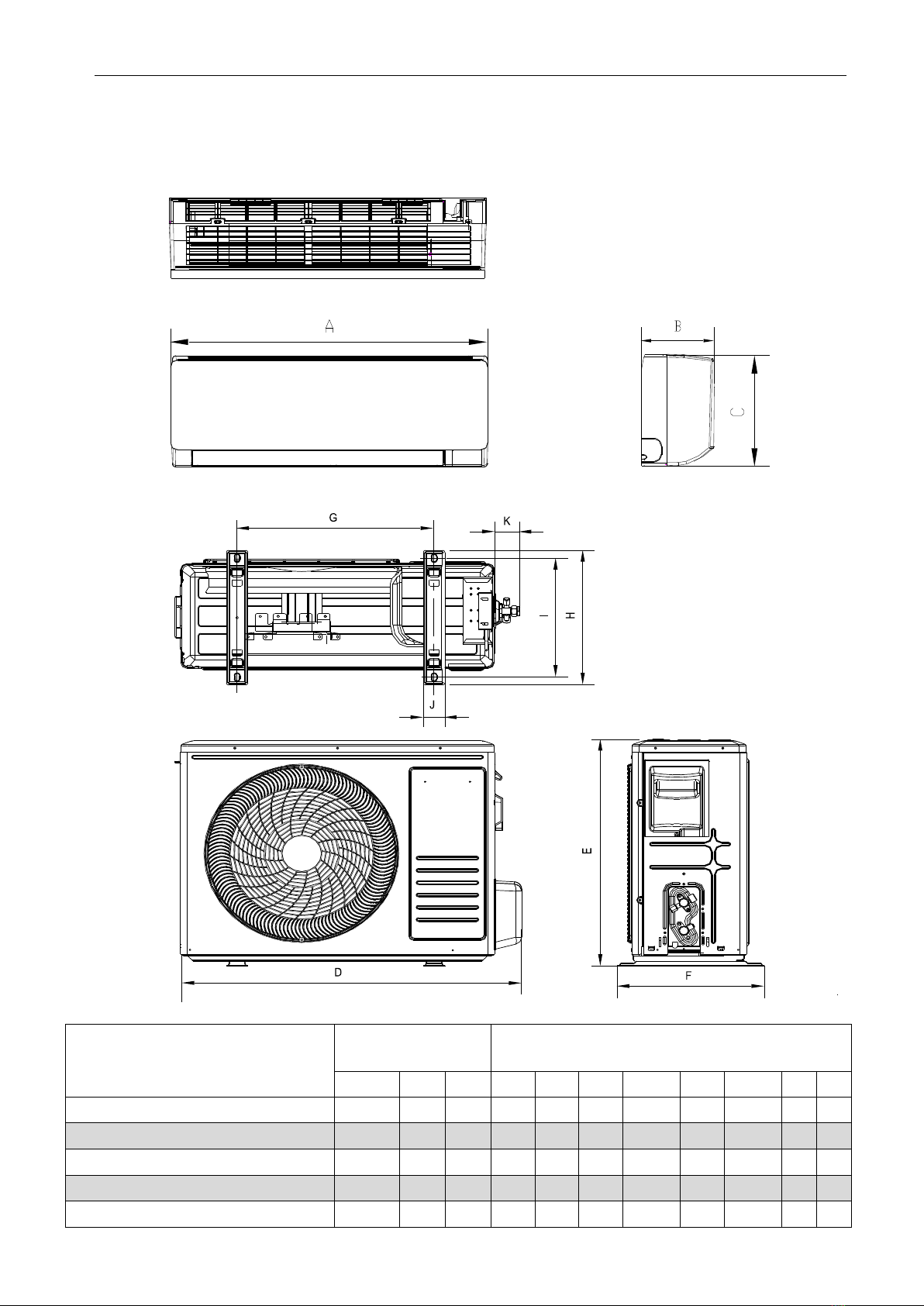
2. Product Dimensions
Indoor Unit:
Outdoor Unit:
Air Conditioner Service Manual
Model Indoor unit Outdoor unit
A B C D E F G H I J K
MRL0923E/MRL0923C 698 190 255 667 507 276 375 276 256 52 55
MRL1213E/MRL1213C 777201 250 767 552 300 439.2 302 277.8 48 55
MRL1223E/MRL1223C 777201 250 767 552 300 439.2 302 277.8 48 55
MRL1823E/MRL1823C 910 206 294 831 553 300 508 302 277.8 48 55
MRL2423E/MRL2423C 1010 220 315 890 605 357 518 357 329 55 63
2

Air Conditioner Service Manual
3. Refrigeration cycle diagram
Cooling only
Heat pump
Capillary
Compressor
Accumulator
Heat exchange
(condenser)
Heat exchange
(Evaporator)
2-way valve
Liquid side
3-way valve
Gas side
Cooling
Heating
Gas side
3-way valve
Liquid side
2-way valve
Heat exchange
(Evaporator)
Heat exchange
(condenser)
Accumulator
Compressor
4-way valve
Capillary Assembly
Check valve
3
Note: Each mode and relevant function will be further specified in following pages.
Air Conditioner Service Manual
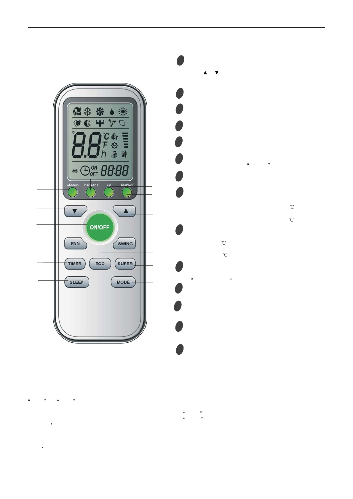
Remote Control
Note :
The remote controller is not presetting as Cooling Only Air Conditioner or Heat Pump by manufacturer.
Each time after the remote controller replace batteries or is energized, the arrowhead will flashes on the front of
Heat or Cool on LCD of the remote controller.
User can preset the remote controller type depending on the air conditioner type you have purchased as follows:
Press any button when the arrowhead flashes on the front of Cool , Cooling Only is set.
Press any button when the arrowhead flashes on the front of Heat , Heat Pump is set.
If you don t press any button within 10 seconds, the remote controller is preset as Heat Pump automatically.
If the air conditioner you purchased is a Cooling Only one, but you preset the remote controller as Heat Pump, it
doesn t bring any matter. But if the air conditioner you purchased is a Heat Pump one, and you preset the remote
controller as Cooling Only, then you CAN NOT preset the Heating operation with the remote controller.
Remote controller 1
2
4
3
5
6
9
7MODE button
ECO button
ON/OFF button
FAN SPEED button
TEMP UP button
TIMER button
SLEEP button
TEMP DOWN button
To select the mode of operation.
In cooling mode,press this button ,the temperature
will increase 2 on the base of setting temperature:
In heating mode, press this button, the temperature
will decrease 2 on the base of setting temperature.
To switch the conditioner on and off.
To select the fan speed of auto/low/mid/high.
To set automatic switching-on/off.
Increase the temperature or time by 1 unit.
To activate the function SLEEP .
Decrease the temperature or time by 1 unit.
4.Operation Details
8SUPER button
In cooling mode, press this button, the unit will give
the maximum cooling temperature with 16
In heating mode, press this button, the unit will give
the maximum heating temperature with 31 .
9
SWING button
10
To activate or deactivate of the movement of the
DEFLECTORS .
12 DISPLAY button
To LED display (if present).switch on/off the
9
3
4
2
1
9
5
67
8
10
11
12
9
CLOCK
11
Press this button to set the time. When the time is flashing,
press or to adjust the time. Every press equals one
minute,or press and hold for rapid adjustment. Press
CLOCK again once the time has been set.
.
13
14
12 3D
9
13
When you press "3D", the horizontal and vertical
vanes will swing together at the same time.
12
14 HEALTHY button
To switch - on /off HEALTHY function. It is a button
which controls the ionizer or plasma generator only
for inverter type.
4
Air Conditioner Service Manual
Electronic controller
NOTES:
RT-------Room Temperature.
IPT------Indoor Pipe Temperature.
ST------indoor Setting Temperature.
OPT---Outdoor Pipe Temperature.
CRT---Compensated Room Temperature
1. Automatic mode
1) The initial RT determines A/C working mode and the setting temperature (ST), the mode is
determined effective only once unless A/C shut-down and then re-started. If from other mode
switches to automatic mode (including mode conversion after shutdown), it should be that the
compress stop more than 3 min then temperature judgment and automatic mode are conducted (it
can conduct immediately from fan mode switched to automatic, the indoor fan stops, three minutes
later the response is made and start up). Within 3 min, the output as: Showing the room
temperature, indoor fans starts (or anti-cold airflow), the outdoor fan stops;
Withautore‐startcontroller,oncebeingturnedofforincaseofanaccidentlypowercut,theA/Cisableto
retainandrestoretheoriginalmodewhenbeingturnedonorthepowersupplyisresumed,iftheauto
restartfunctionactivated.power‐offafterpower‐on;whileiftheautorestartfunctionisn’tactivated,
theA/Centersstandbystate.
Heat pump
Mode Initial RT Initial ST
Cooling RT≥26°C 23°C
Dry 26°C>RT≥20°C 7°C
Heating RT<20°C 23°C
Cooling-only
Mode Initial RT Initial ST
Cooling RT≥26°C 23°C
Dry 26°C>RT≥20°C 7°C
Ventilating RT<20°C -
Under automatic mode (including from automatic converted into Dry mode), when A/C received the
temperature UP or DOWN signals from the remote controller, the setting temperature (ST)
adjusts
correspondingly to the current room temperature plus or minus 1°C, the automatic regulating
temperature range is ± 2°C.
2. Cooling mode
1) The control of the compressor
a.
When RT-ST≥1°C,the compressor is running.
b.
When RT-ST<-1°C,the compressor stops.
c.
When-1°C≤RT-ST<1°C, the compressor keeps its original state.
2) Outdoor fan motor and the compressor run simultaneously (except for defrosting).
3) The control of indoor fan motor:
a.
Indoor fan motor can operate by automatic, low, middle, or high airflow speed circularly.
5
Air Conditioner Service Manual
b.
Indoor fan motor automatic airflow speed control, it works as shown in Figure 1:
Hi
Mid
Lo
RT-ST 1°C 2°C 4°C
Figure 1 Cooling automatic airflow
When the temperature changing leads the fan speed variation, the switch can only be made orderly,
and in every grade of air flow speed should run 1 minute at least.
3. Dry mode
While select to this mode, the air conditioner operates for 3 minutes according to cooling mode firstly
(ST set at 7°C), and then takes the detected backflow air temperature minus 2°C as a new set
temperature (the lowest temperature: 5°C) and runs according to cooling mode, indoor fan operates at
low-speed, at this moment the setting operation of fan speed invalid but Swing adjustable.
4. Heating mode
On the Heating mode, the room temperature (RT) is compensated (CRT), after that, the room
temperature displayed on the LED is CRT=RT-3°C.
1) The control of the compressor
a.
When ST-CRT≥1°C,the compressor is running.
b.
When ST-CRT<-1°C,the compressor stops.
c.
When -1°C≤ST-CRT<1°C, the compressor keeps its original state
2) Outdoor fan motor and the compressor run simultaneously (except for defrosting)
3) The control of indoor fan motor:
a.
Indoor fan motor can operate by automatic, low, middle, or high airflow speed circularly.
b.
Indoor fan motor automatic airflow speed control, it works as shown in Figure 2:
Figure 2 Heat automatic airflow
When the temperature changing leads the fan speed variation, the switch can only be made orderly,
and every grade of air flow speed should run 1 minute at least.
4) Vane motor control: run as set state.
5) 4-way valve control:
a.
Under heating mode, the four-way valve maintains well-connected status (including the
compressor stops on set condition, except for the defrosting process)
b.
When the mode switches into the heating mode or A/C start-up, four-way valves will open 5
Seconds before the compressor starts; while the mode exits from the heating mode or A/C turn off,
the four-way valve will close 2min later after shut-down the compressor.
Hi
Mid
Lo
ST-CRT 1°C 2°C 4°C
6
6) Defro
During de
buzzer an
defrosting
During de
Fan spee
Except th
buzz for r
During de
Defrosting
Option 1
The cond
Condition
Definition
The follow
a.
IPT1 s
b.
t5≥50m
be less th
c.
IPT<4
Running i
defrosting
Condition
accumula
under con
Condition
less than
temperatu
and the m
osting functio
efrosting, on
nd display w
gfinished;
efrosting, the
ed and/or Sw
he above sig
response.
efrosting, ele
gEnter and
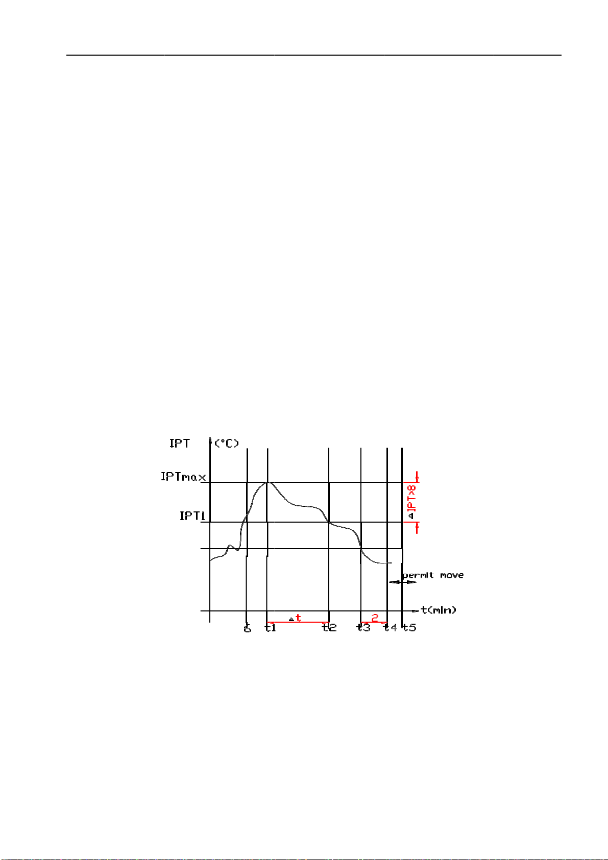
:with jump
dition ofente
n1:As show
n:
wing conditio
settles for IP
min(running
han t1)
40°C,and l
into defrostin
gcycle, the d
n2: When ru
atively), the i
ndition 2, de
n3: After the
n23°C (cold
ure dropping
machine run
on:
ce mode ch
will make res
esignals of O
wing should b
nal process
ectrical heati
Exit program
per JC
er defrosting:
wn in figure
ons a, b and
PT1=IPTma
gtime t5≥50
lasts 2min。
ng on condit
defrosting tim
unning time i
indoortemp
efrosting time
ecompresso
air preventi
gwhen com
s into defros
Air C
anging, eco
sponse imme
On-Off, Tim
be in accord
ing during d
ing (optiona
m:
:run into de
3
dc all require
ax-ᇞIPT
0min(the co
tion 1, the fir
me should b
is more than
erature is le
eset is 8 mi
or is operatin
on wind tem
mpressorope
sting accordi
Conditioner Se
nomic opera
ediately, but
ing, Sleep, F
dance with o
efrosting, no
l function) st
frosting onc
ed to meet:
ompressor ru
rst running ti
be determine
Figure 3
nor equal to
ss than 35°C
n.
ng for20min
mperature) w
erating, not i
ing to any on
rvice Manual
ation ortemp
tthe other o
Fan speed a
operation for
oother signa
tops compu
e any of con
uns cumulati
me of set de
ed and adjus
3
120 min (co
Cfor 2 min s
continuous
when the fan
ncluding the
ne condition
perature set
perations wo
and/or Swing
rCold Air Pr
als will deal
lsively.
ndition 1, 2,
vely),t5 is re
efrosting is F
sted.
ompressoris
sustained. R
ly, the indoo
stops runni
ecompresso
as below.
tting signals
on’t impleme
gcan respon
revention.
with, only a
and/or 3 me
emovable,a
F(8min); afte
srunning
Running into
or pipe temp
ng (including
or’s starting
received, th
ent until
nd, but the
voice of
et.
and could
er running a
defrosting
erature is
g
up course),
he
a
7
Air Conditioner Service Manual
Running into defrosting under condition 3, defrosting time set is 10 min.
a) Running into the first defrosting in 20 min after start-up.
b) The interval from last defrosting equivalent to or more than 50 min (stopping the compressor or the
machine in standby is allowed in the meantime).
Option 2: Without Jumper JC, and no OPT outdoor sensor
when the compressor runs for 45 min (accumulated), if the indoor coil temperature is less than 40°C for
2 min, the machine runs into defrosting, and lasts for 3min, otherwise when the compressor
runs for 120 min (accumulated), the machine runs into defrosting automatically and last for 10 min.
Option 3: Without jumper JC, but with OPT outdoor sensor
While heating, when the temperature of condenser is lower than E °C (-4°C), and the compressor runs
for 45 min (accumulated), then the machine runs into defrosting and lasts for 10 min.
Option 4. On heating, while the outdoor fan motor stopped but the compressor operated
accumulative totally 30min, then the machine runs into defrosting and last for 8 min. if the accumulative
totally less than 30min, but accord with one of the condition option 1-3 then the machine runs into
defrosting at the option 1-3 and the accumulative total time restarts from 0.
Conditions for quitting defrosting
(1) The quitting conditions for option 1, option 2 and 4, the machine quits from defrosting if any one
below condition met.
6
a. Defrosting time is over.
7
b. When it runs in defrosting for three minutes, the IPT indoor coil temperature rises 15°C or above
from the bottom point.
(2) The quitting conditions for option 3.
When OPT ≥20°C or defrosting for more than 10 min, then quit from defrosting.
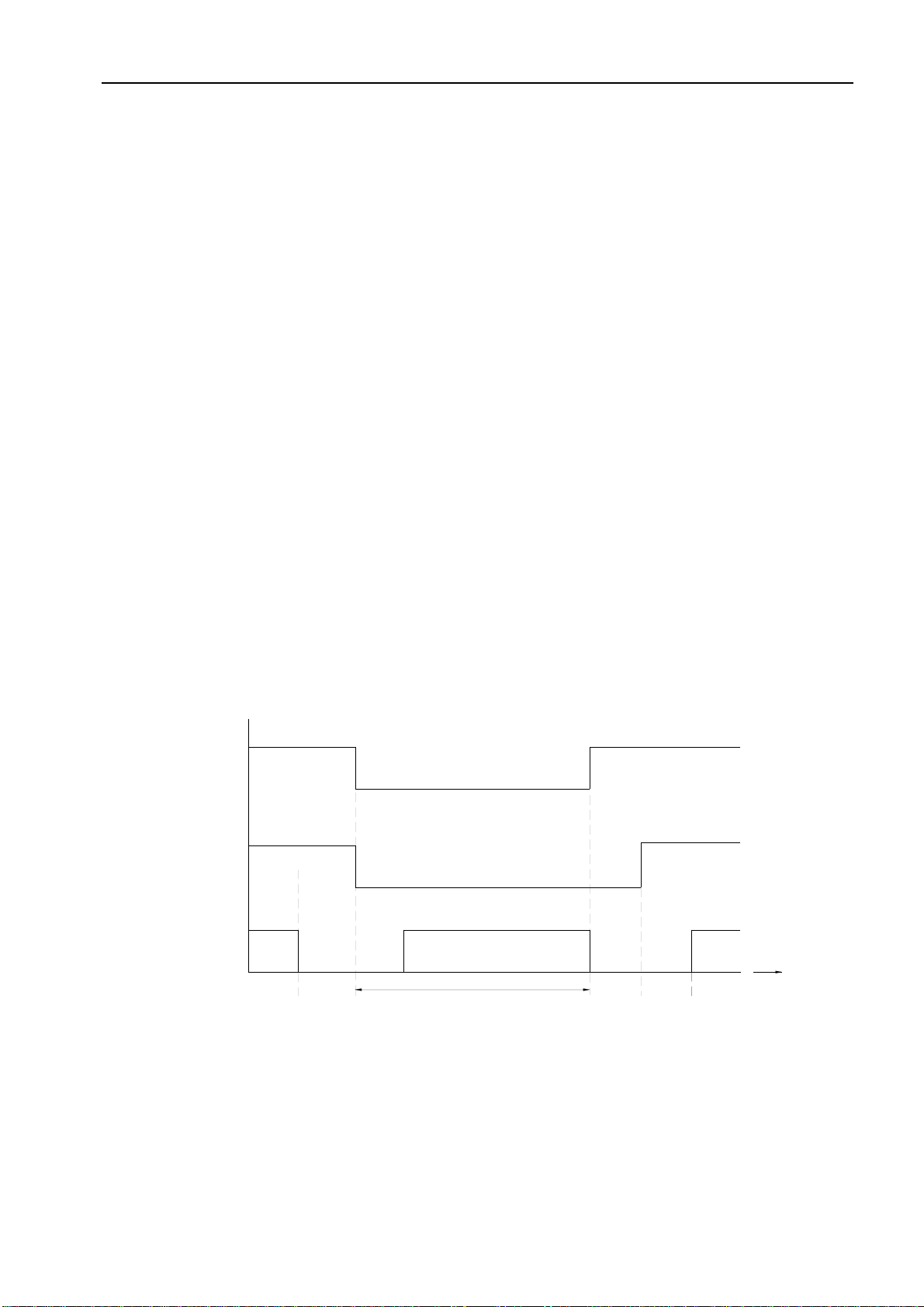
(3) Defrosting process shown in Figure 4
Figure 4 Defrosting process
7) Auxiliary electric heating function (optional)
(1) The default condition is automatic on/off the electric heating function.
(2) The conditions of auxiliary electric heating works (all the following conditions must be met)
a.
the compressor runs for more than 3min;
b.
indoor fan runs normally;
c.
not in defrosting state;
Compressor Relay
ON
OFF ON
ON
OFF
OFF
ON
ON
ON
OFF
39S 19S 5S
t
4-way Valve
Outdoor Fan
The indoor fan runs in anti-cold wind modle
Defrosting time MAX 12 Min
ON
8

Air Conditioner Service Manual
d.
auxiliary electric heating is turned off for more than 30s。
e.
ST-RT≥0°C;
f.
RT﹤25°C;
g.
IPT≤43°C;
(3) The conditions of stopping auxiliary electric heating(any one of the following conditions met, the
state stops)
a.
the compressor stops
b.
RT≥27°C;
c.
IPT≥50°C
d.
indoor fan stops。
e.
running into sleeping function
5. Fan mode
1) Indoor fan motor is running at setting speed (the speed same as heating mode).
2) Vane motor control: running according to the setting condition.
3) The outdoor unit doesn’t work under fan mode.
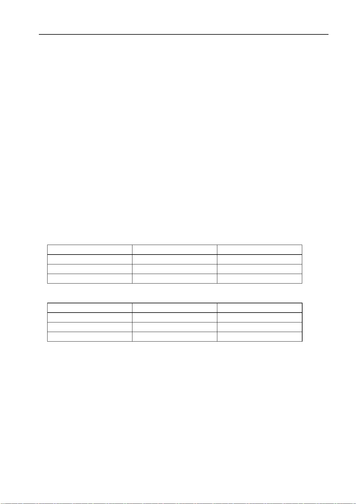
6. Sleeping mode
1) Under sleep mode, the indoor fan motor running at low speed, except the power light and sleep
light are ON, timer lights ON/OFF according to the setting state, running light OFF. LED will be OFF
after displaying 30S.
2) Temperature control:
(1) While changing from Cool mode to Sleep mode, one hour later, the operation Temp.=ST+1°C,
another one hour later, the operation Temp.=ST+2°C,after then the temperature has no changed
anymore.
(2) When changing from Heating mode to Sleep mode, one hour later, the operation Temp.= ST-1°C,
another one hour later, the operation Temp.=ST-2°C,after then no changed anymore.
3) The machine will automatically shut up after running 10 hours under sleep mode.
When Timer ON and Sleep mode are implemented at the same time, the Sleep mode can not be
functioned.
7. Timer function
The timer can preset between 10min to 24h, when the time set less than “10” hours, the displayed
time shown by 0.5 hour as the unit, when the time set more than or equal to “10” hours, the
displayed time shown by 1 hour as the unit.
8. Emergency switch (ON/OFF)
1) When stand-by, to operate by pressing the emergency switch as follows:
Press the emergency switch within 3 seconds, release emergency switch while the buzzer rings once,
the machine goes into Cooling mode. If the buzzer rings twice while release emergency switch,
Heating mode is selected. To press the Emergency switch while A/C is on, the buzzer rings once and
then A/C will shut down.
2) The machine runs mandatorily as selected mode within 30min when Emergency operated,
meanwhile indoor fan motor runs in high-speed, and stepping vane swinging as well. 30min later
the A/C goes into automatic mode under the same operation manner, the set temperature to be
23°C, and the rotate speed of indoor fan motor automatic control, stepping vane swinging all the way.
3) To press the emergency button when the A/C goes on operation, then the machine runs into
stand-by.
9

Air Conditioner Service Manual
4) Under emergency operation, the function of compressor’s time-delay protection, Anti-frosting
protection in cooling mode, Overheating protection in heating mode, sensor fault protection and
defrost operate are effective.
5) Under emergency operation, once effective signal from remote controller received, the A/C
exits form of emergency mode without delay, and operates according to the setting value from remote
controller immediately.
9. Auto-restart function
1) The PCB retains the setting parameters in case of power off. When the power supply is resumed,
the machine, which has been started up the power-off memory function, is able to restore into the
original running state automatically.
To press the emergency button and power on the unit, and hold on for10 seconds, The buzzer
2) will ring three times, after this operation, the auto restart function activated.
3) To close auto restart function while it is activated, repeat process as above 2), the buzzer will ring
four times.
10. Protection / Failure code
10.1 Protection
1) Compressor’s protection:
a. The PCB which with Auto-restart function, once it is activated, the compressor goes along 3min
delay protection when power on, otherwise the compressor without this protection even when the PCB
is power-on.
b . The compressor’s 3 min interval protection: the compressor can’t start-up until it stops 3 min later.
(except for the defrosting process).
c. .After the compressor started, it’s operation state remains the same within 3 min even when ST, RT
variation.
2) Anti-frosting protection of indoor evaporator (Cooling mode):
If IPT≤0°C detected in consecutive 3 min, compressor and outdoor fan motor to be stopped operation,
indoor fan motor runs at high-speed forcibly; i f IPT≥5°C detected 3min later, then outdoor fan motor
and compressor will start up, and indoor fan motor restores to it’s original state.
3) Overheating protection (Heating mode):
If IPT≥55°C, the outdoor fan motor: OFF.
If IPT≥65°C, the compressor: OFF, and indoor fan motor runs at
high-speed forcibly.
When IPT≤48°C, the outdoor fan motor and the compressor start up, indoor fan motor restores to it’s
original state.
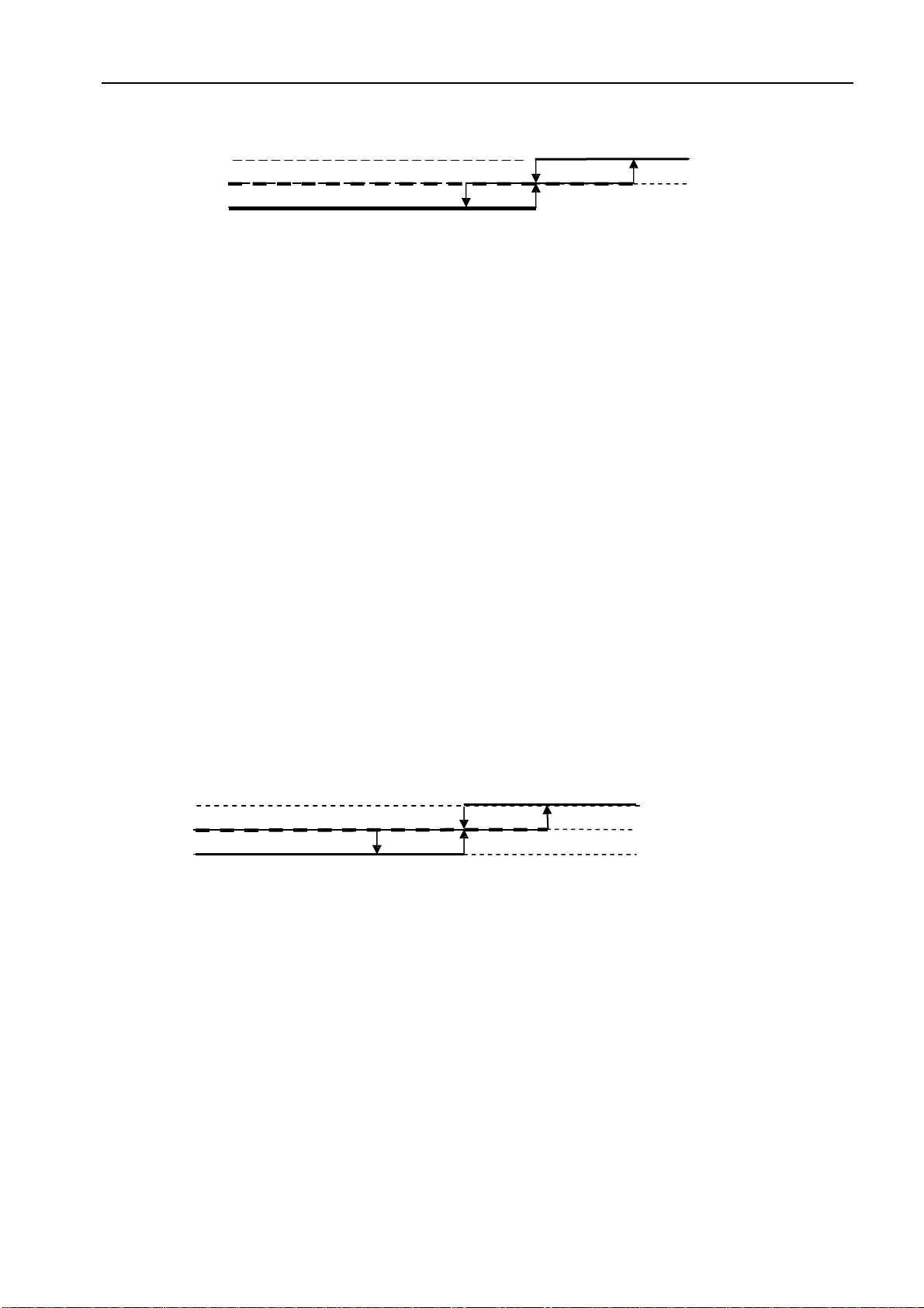
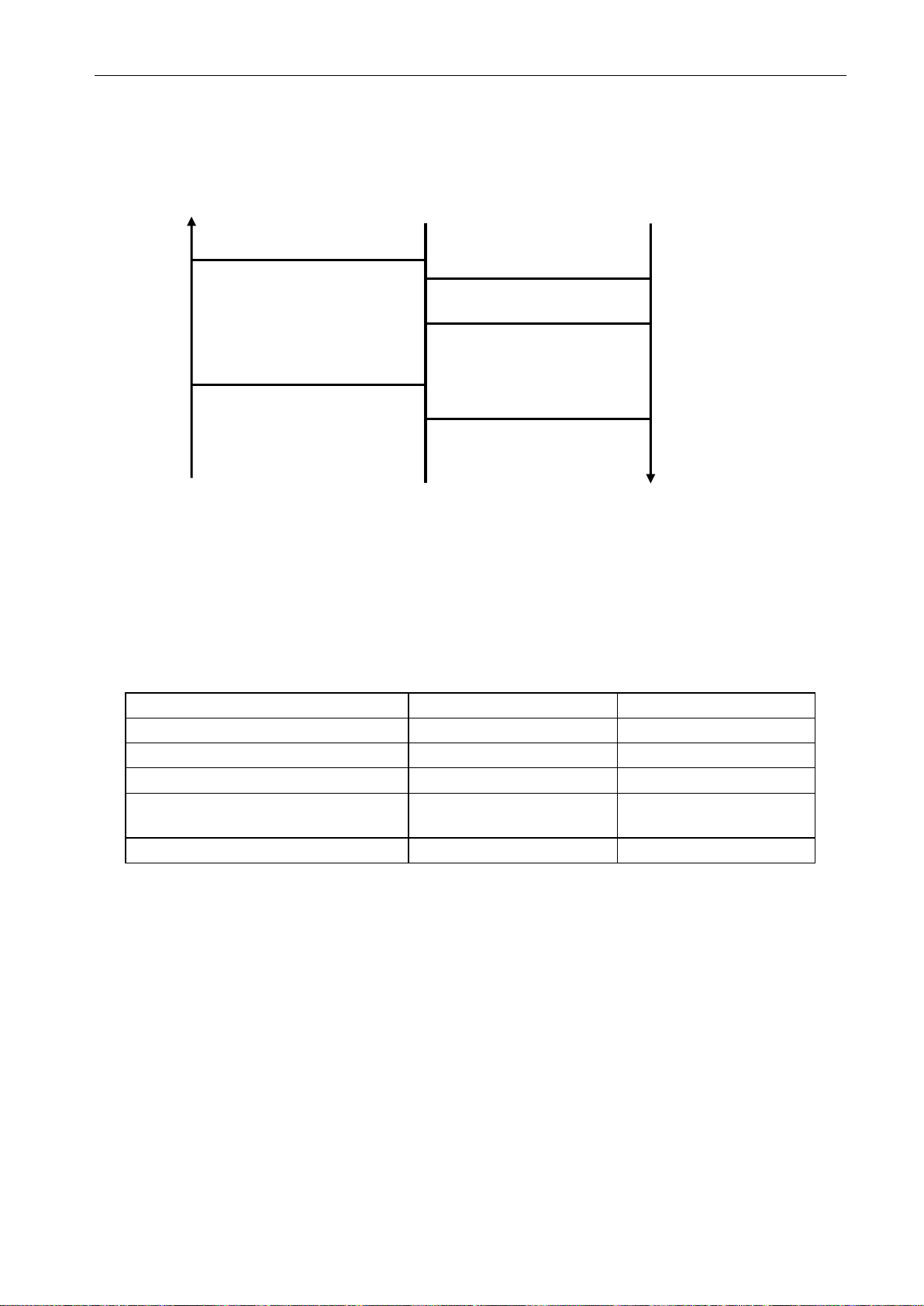
4) Cold air prevention (Heating mode):
This function is intend to prevent cold air from being discharged when the heating operation starts or
when defrosting.
a.
When running into the heating mode, once the compressor fails to comply with the start-up
conditions, the fan speed is regulated according to the coil temperature within 2 min, 2 min later the
indoor fan motor stops. If the compressor starts up within 2 min, then operating according to Figure 5.
Under heating process, while the compressor stop (including stopping for protection), the fan motor’s
operation (including stopping the indoor fan motor) is regulated according to the coil temperature
within 1min, 1min later the fan will be stopped forcibly.
10
b. When the indoor fan motor running at a low-speed under cold air prevention operation, once
auxiliary electric heating works, the vane immediately withdraws from the cold air prevention
location and turn back to normal vane angle. While auxiliary electric heating stops, indoor fan motor
goes on to run at low-speed accordingly, the vane turns to cold air prevention location
Figure 5 Cold air prevention
10.2 Failure code
The following table shows the fault protections.
When failures happens, the PCB alarms and buzzer rings three times, Failure code shows on
display board, and the PCB operates protection procedures.
Failure code: For the machine with LED display (88), the code shows on LED, for machine without
LED, the code reflects by the running light.
Failure
Running Light Flash
LED Display (88)
RT Sensor Failure
Once / cycle
E1
IPT Sensor Failure
Twice / cycle
E2
System Protection
4 times/cycle
E4
System Protection(high/low pressure
protection model)
E5
Indoor Fan Motor Failure
6 times / cycle
E6
While failure happens, the code displayed statically, if there are several failure codes reported at
the same time, then failure codes appears by turns every eight seconds correspondingly.
6
a. Sensor’s failure protection: when the sensor tested temperature out of the range ---
50°C≤T≤110°C, sensor failure is determined.
Once RT and/or IPT sensor failure appears, the compressor stops, and indoor and outdoor fan
motors shut off. Remote controller doesn’t response to any signal except for
shutdown. During failure
the machine can run in fan mode. After the failure is settled, the PCB restores to standby status.
7
b. Failure protection of Indoor PG fan motor: If there is no feedback signal of rotated speed within 5s,
the indoor fan motor stops, meanwhile, the compressor, outdoor fan motor, four-way valve and/or
auxiliary electric heater etc. also cut down.
The indoor fan motor restarts again 10 seconds later, if still there is no feedback signal of rotated
speed within 5 seconds, the A/C stops and goes into indoor fan motor failure protection, buzzer
rings three times, and running light flashes at 6 times per 8 seconds. Once there is feedback signal
while the failure recovery, the failure will relieve automatically.
Set fan speed
Temperature dropping
Temperature rising
Stop the fan motor
Stop the fan motor
25°C
34°C
27°
23°C
Set fan speed
Low speed
32°
C
Low speed
Air Conditioner Service Manual
5 times/cycle
11

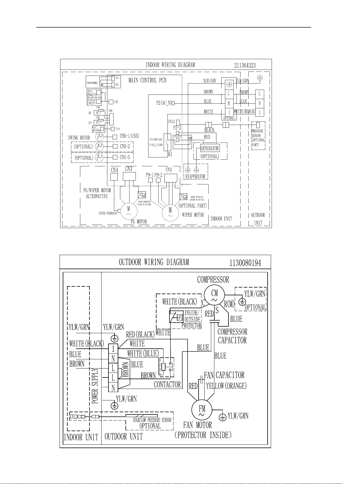
5.
Wiring diagram
MODEL: 05/(05/&05/(05/&05/(05/&05/(05/&
INDOOR UNIT
287'22581,7
Air Conditioner Service Manual
12
MODEL: 05/(05/&
INDOOR UNIT
Air Conditioner Service Manual
OUTDOOR UNIT
13
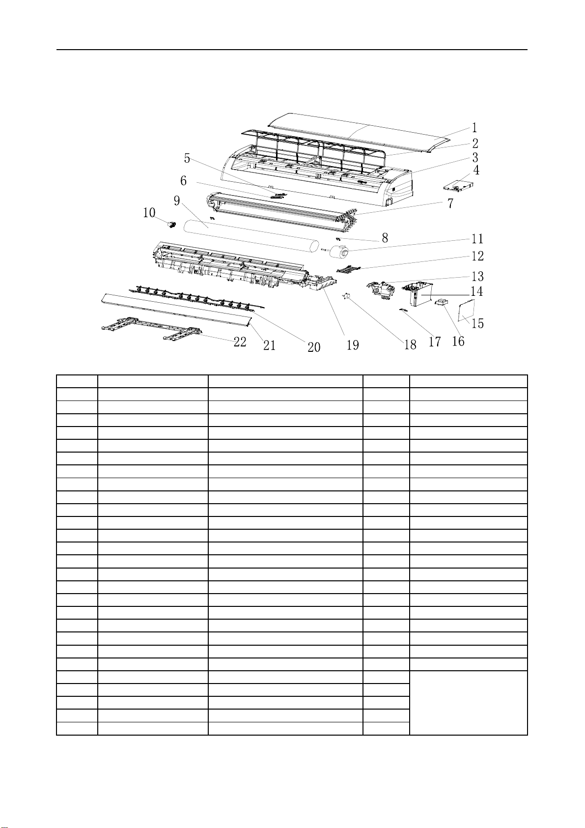
6. Explosion view and parts
Indoor Unit-MRL0923E
No. Part No. Part Name Q’ty Remark
1 41106-002200 Front Panel 1
2 42008-000070 Air Filter 2
3 41106-002347 Face Frame 1
4 41105-000146 Electrical Box Cover 1
5 31102-000084 Display PCB 1
6 42003-000001 Display PCB Box 1
7 92011-002882 Evaporator 1
8 41108-000066 Screw Cover 2
9 42004-000040 Cross Fan 1
10 42007-000001 Bearing Mount 1
11 22001-000269 Indoor Motor 1
12 41101-000242 In And Out Pipe Fixer 1
13 42003-000060 Indoor Motor Cover 1
14 41105-000104 Electrical Box 1
15 31101-000542 Main PCB 1
16 10502-100028 Transformer 1
17 42001-000103 Cable Clamp 1
18 22001-000313 Vane Motor 1 1
19 41199-003279 Base 1
20 41101-000042 Vertical Vane Assembly 2
21 41103-000103 Vane 1
22 41109-000042 Installation Plate 1
23 10104-100014 Indoor Sensor Assembly 1
24 22013-000946 Remote Controller 1
26 A1101-008360 Indoor Carton 1
27 A2006-000050 Left Foaming 1
28 A2006-000030 Right Foaming 1
Air Conditioner Service Manual
Not shown in Explosion
view
14
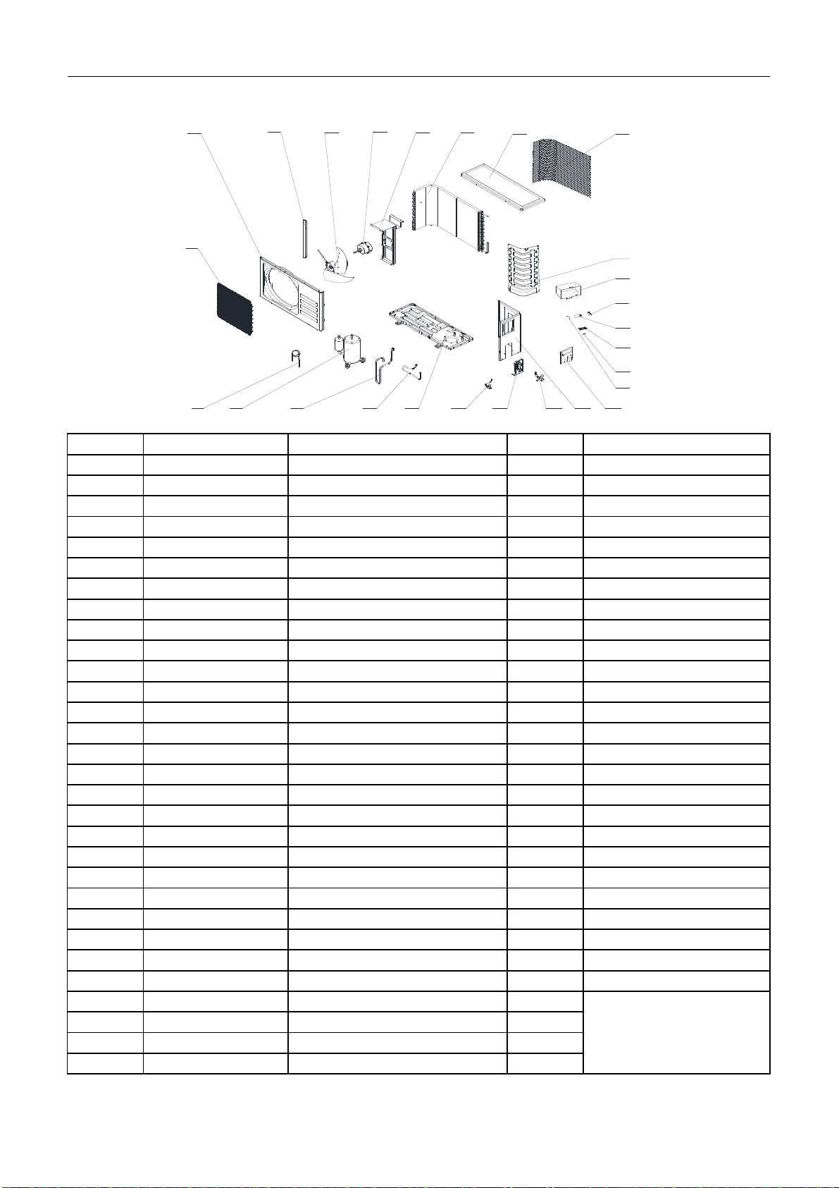
No. Part No. Part Name Q’ty Remark
1 42011-000108 Grille 1 Optional
2 41207-000017 Top Cover 1
3 92011-000904 Condenser 1
4 41203-000038 Outdoor Motor Supporter 1
5 22001-000012 Outdoor Motor 1
6 42004-000072 Propeller Fan 1
7 41205-000126 Left Grille Supporter 1
8 41206-000030 Front Plate 1
9 42011-000068 Fan Guard 1
10 92007-001823 Capillary Assembly 1
11 92014-000249 Compressor 1
12 92006-000320 Discharge pipe 1
13 92006-001480 Suction pipe 1
14 41202-000163 Base 1
15 92008-000043 Two-way Valve 1
16 41204-000012 Valve Supporter 1
17 92008-000115 Three-way Valve 1
18 41205-000056 Right Plate 1
19 41201-000004 Electrical Box Cover 1
20 42001-000029 Capacitor Strip 1
21 42001-000035 Cable Clamp(φ7) 1
22 11304-100006 terminal 1
23 22003-000005 Compressor Capacitor 1
24 10303-100020 Fan Motor Capacitor 1
25 41214-000342 Electrical Parts Box 1
26 41208-000118 Partition plate 1
27 A1401-000010 Base carton 1
28 A1201-008997 Cabinet carton 1
29 A1202-000035 Base foaming 1
30 A1202-000001 Cover foaming 1
Air Conditioner Service Manual
Outdoor Unit- MRL0923C
Not shown in the Explosion
view.
11 12 13 14
10
8
9
6
75
18
15 16 17 19
20
25
24
23
22
21
4321
26
15

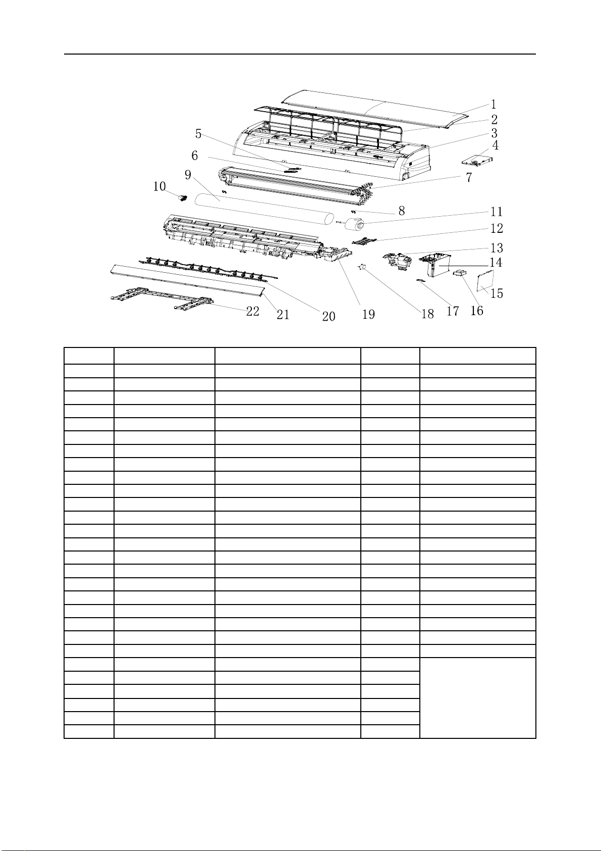
Indoor Unit- MRL1213E
No. Part No. Part Name Q’ty Remark
1 41106-002199 Front Panel 1
2 42008-000037 Air Filter 2
3 41106-002371 Face Frame 1
4 41201-000068 Electrical Box Cover 1
5 31102-000084 Display PCB 1
6 42003-000001 Display PCB Box 1
7 92011-002812 Evaporator 1
8 41108-000066 Screw Cover 1
9 42004-000039 Cross Fan 1
10 42007-000001 Bearing Mount 1
11 22001-000238 Indoor Motor 1
12 41101-000242 In And Out Pipe Fixer 1
13 42003-000060 Indoor Motor Cover 1
14 41105-000104 Electrical Box 1
15 31101-000461 Main PCB 1
16 10502-100033 Transformer 1
17 42001-000112 Cable Clamp 1
18 22001-000313 Vane Motor 1 1
19 41199-002735 Base 1
20 41101-000081 Vertical Vane Assembly 2
21 41103-000101 Vane 1
22 41109-000042 Installation Plate 1
23 10104-100014 Indoor Sensor Assembly 1
24 42009-000011 Drainage Hose 1
25 22013-000946 Remote Controller 1
27 A1101-007306 Indoor Carton 1
28 A2006-000052 Left Foaming 1
29 A2006-000032 Right Foaming 1
Air Conditioner Service Manual
Not shown in Explosion
view
16
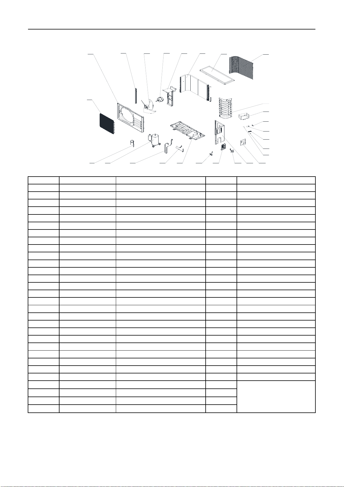
No. Part No. Part Name Q’ty Remark
1 42011-000109 Grille 1 Optional
2 41207-000023 Top Cover 1
3 92011-000274 Condenser 1
4 41203-000037 Outdoor Motor Supporter 1
5 22001-000015 Outdoor Motor 1
6 42004-000070 Propeller Fan 1
7 41205-000124 Left Grille Supporter 1
8 41206-000041 Front Plate 1
9 42011-000084 Fan Guard 1
10 92007-001993 Capillary Assembly 1
11 92014-000308 Compressor 1
12 92006-000246 Discharge pipe 1
13 92006-001394 Suction pipe 1
14 41202-000062 Base 1
15 92008-000018 Two-way Valve 1
16 41204-000010 Valve Supporter 1
17 92008-000127 Three-way Valve 1
18 41205-000062 Right Plate 1
19 41201-000005 Electrical Box Cover 1
20 42001-000030 Capacitor Strip 1
21 42001-000038 Cable Clamp 1
22 11304-100006 terminal 1
23 22003-000006 Compressor Capacitor 1
24 10303-100016 Fan Motor Capacitor 1
25 41214-000342 Electrical Parts Box 1
26 41208-000121 Partition plate 1
27 A2005-000517 Base carton 1
28 A1201-007910 Cabinet carton 1
29 A1202-000027 Base foaming 1
30 41213-000027 Cover foaming 1
Air Conditioner Service Manual
Outdoor Unit- MRL1213C
Not shown in the Explosion
view.
11 12 13 14
10
8
9
6
75
18
15 16 17 19
20
25
24
23
22
21
4321
26
17
Indoor Unit- MRL1223E
No. Part No. Part Name Q’ty Remark
1 41106-002199 Front Panel 1
2 42008-000037 Air Filter 2
3 41106-002371 Face Frame 1
4 41201-000068 Electrical Box Cover 1
5 31102-000084 Display PCB 1
6 42003-000001 Display PCB Box 1
7 92011-002812 Evaporator 1
8 41108-000066 Screw Cover 1
9 42004-000039 Cross Fan 1
10 42007-000001 Bearing Mount 1
11 22001-000261 Indoor Motor 1
12 41101-000242 In And Out Pipe Fixer 1
13 42003-000060 Indoor Motor Cover 1
14 41105-000104 Electrical Box 1
15 31101-000465 Main PCB 1
16 10502-100021 Transformer 1
17 42001-000103 Cable Clamp 1
18 22001-000313 Vane Motor 1 1
19 41102-000116 Base 1
20 41101-000081 Vertical Vane Assembly 2
21 41103-000101 Vane 1
22 41109-000042 Installation Plate 1
23 10104-100014 Indoor Sensor Assembly 1
24 42009-000011 Drainage Hose 1
25 22013-000946 Remote Controller 1
27 A1101-007309 Indoor Carton 1
28 A2006-000052 Left Foaming 1
29 A2006-000032 Right Foaming 1
Air Conditioner Service Manual
Not shown in Explosion
view
18

No. Part No. Part Name Q’ty Remark
1 42011-000109 Grille 1 Optional
2 41207-000023 Top Cover 1
3 92011-000274 Condenser 1
4 41203-000037 Outdoor Motor Supporter 1
5 22001-000013 Outdoor Motor 1
6 42004-000070 Propeller Fan 1
7 41205-000124 Left Grille Supporter 1
8 41206-000041 Front Plate 1
9 42011-000084 Fan Guard 1
10 92007-001942 Capillary Assembly 1
11 92014-000223 Compressor 1
12 92006-000279 Discharge pipe 1
13 92006-001442 Suction pipe 1
14 41202-000062 Base 1
15 92008-000018 Two-way Valve 1
16 41204-000010 Valve Supporter 1
17 92008-000131 Three-way Valve 1
18 41205-000062 Right Plate 1
19 41201-000005 Electrical Box Cover 1
20 42001-000030 Capacitor Strip 1
21 42001-000035 Cable Clamp(φ7) 1
22 11304-100006 terminal 1
23 22003-000009 Compressor Capacitor 1
24 10303-100019 Fan Motor Capacitor 1
25 41214-000342 Electrical Parts Box 1
26 41208-000121 Partition plate 1
27 A2005-000517 Base carton 1
28 A1201-007911 Cabinet carton 1
29 A1202-000027 Base foaming 1
30 41213-000027 Cover foaming 1
Air Conditioner Service Manual
Outdoor Unit- MRL1223C
Not shown in the Explosion
view.
11 12 13 14
10
8
9
6
75
18
15 16 17 19
20
25
24
23
22
21
4321
26
19
This manual suits for next models
9
Table of contents
Other Everwell Air Conditioner manuals


Popular Air Conditioner manuals by other brands

Samsung
Samsung ADN BDEH Series installation manual

Dometic
Dometic AIRCOMMAND IBIS installation instructions

Komfovent
Komfovent MOU-24HN1-Q installation manual

LG
LG HMC036KDT1 owner's manual

EAS Electric
EAS Electric Super-Slim Cassette Series owner's manual

Carrier
Carrier WeatherExpert Puron 50JC04 installation instructions


