Everwell MGTC0913E-20 User manual

Models
CONTENTS
1. Important Notice
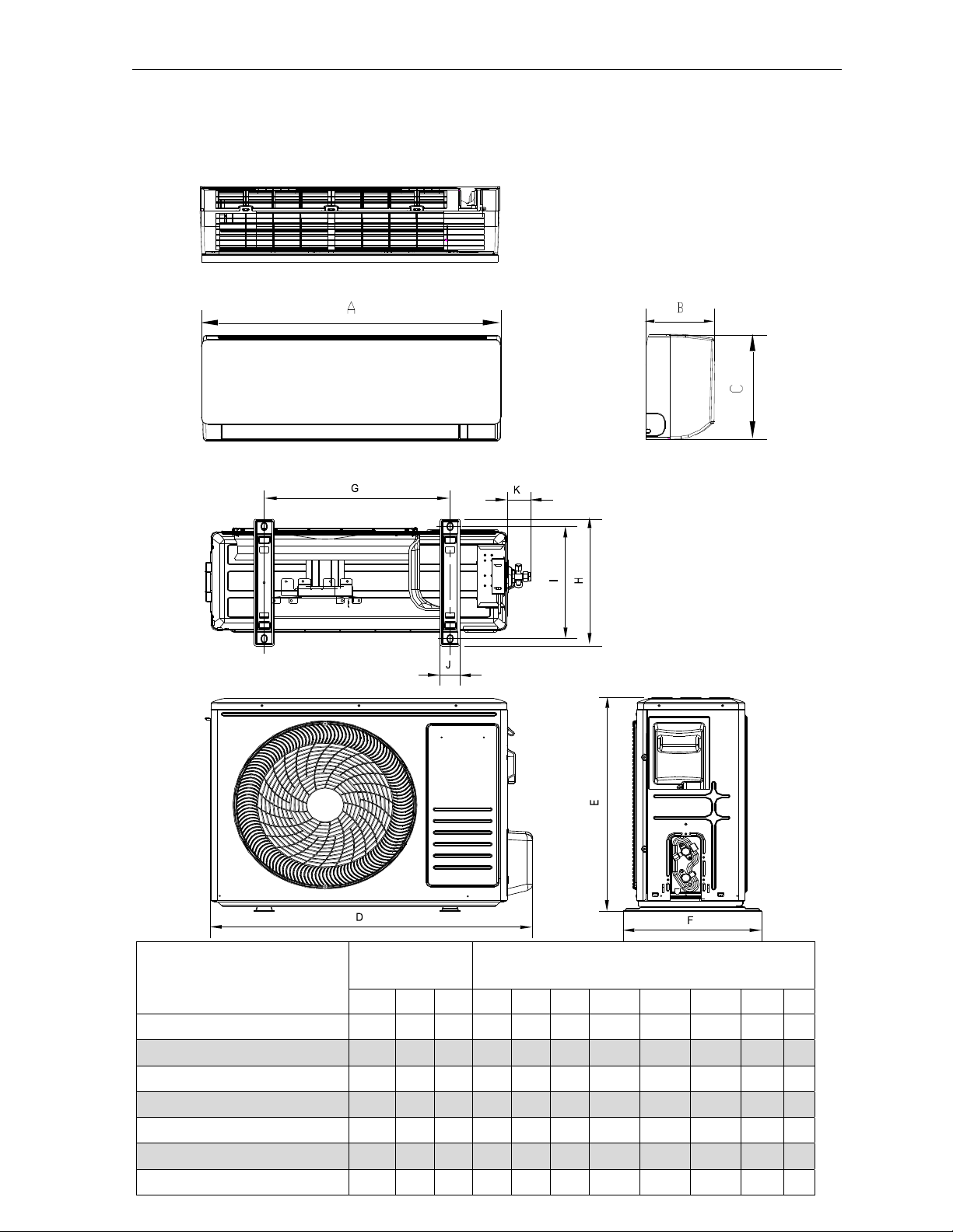
2. Product Dimensions
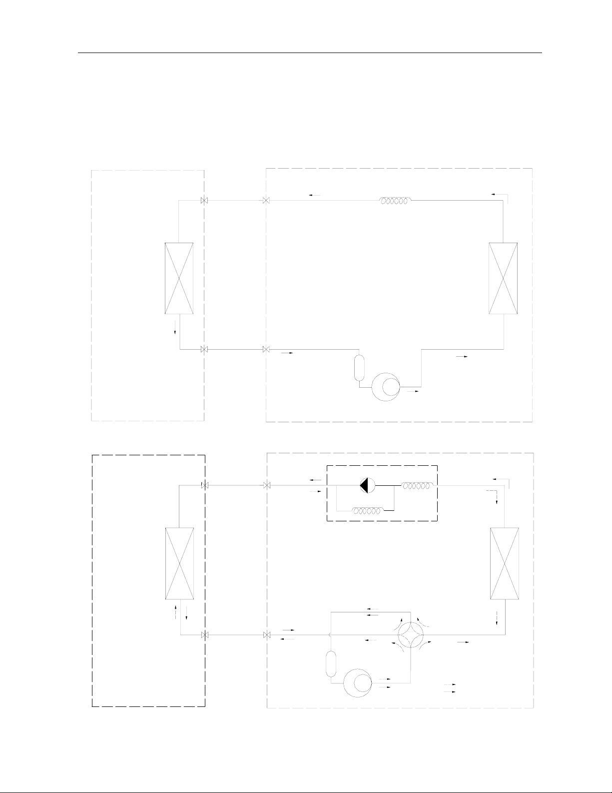
3. Refrigeration cycle diagram
4. Operation details
5. Wiring diagram
6. Explosion view and parts
7. Precaution
8. Names of parts
9. Installation manual
10. Trouble shooting
MGTC0913E-20 /MGTC0913C-20
MGTC0923E-20 /MGTC0923C-20
MGTC1213E-20 /MGTC1213C-20
MGTC1223E-20 /MGTC1223C-20
MGTC1823E-20 /MGTC1823C-20
MGTC2423E-20 /MGTC2423C-20
MGTC3623E-17 /MGTC3623C-17

Air Conditioner Service Manual
1. Important Notice
This service manual is intended for use by individuals possessing adequate
backgrounds of electrical, electronic and mechanical experience. Any
attempt
to repair the appliance may result in personal injury and property
damage.
The manufacturer or seller cannot be responsible for the
interpretation of
this information, nor can it assume any liability in
connection with its use.
The information, specifications and parameter are subject to change due to
technical modification or improvement without any prior notice. The
accurate
specifications are presented on the nameplate label.
How to order spare parts
To have your order filled promptly and correctly, please furnish the
following
information:
1.
Model No. with Indoor or Outdoor
2.
No. in the Explosion View
3.
Part Name
4.
The quantity you ordered
1
Air Conditioner Service Manual
Model
Indoor unit Outdoor unit
A B C D E F G H I J K
MGTC0913E20/MGTC0913C20811 203 292 810 549 305 433.8 305 278 48 55
MGTC0923E20/MGTC0923C20811 203 292 787 498 290 415 291 225 48.5 52
MGTC1213E20/MGTC1213C20811 203 292 810 549 305 433.8 305 278 48 55
MGTC1223E20/MGTC1223C20811 203 292 787 498 290 415 291 225 48.5 52
MGTC1823E20/MGTC1823C201010 220 315 863 602 349 518 357 329 55 63
MGTC2423E20/MGTC2423C201186 258 340 927 699 380 586 374.9 347.5 58.6 63
MGTC3623E17/MGTC3623C171186 258 340 975 808 433 675 399 378 50 63
2
Air Conditioner Service Manual
3. Refrigeration cycle diagram
Cooling only
Heat pump
Capillary
Compressor
Accumulator
Heat exchange
(condenser)
Heat exchange
(Evaporator)
2-way valve
Liquid side
3-way valve
Gas side
Cooling
Heating
Gas side
3-way valve
Liquid side
2-way valve
Heat exchange
(Evaporator)
Heat exchange
(condenser)
Accumulator
Compressor
4-way valve
Capillary Assembly
Check valve
3
Note: Each mode and relevant function will be further specified in following pages.
Air Conditioner Service Manual
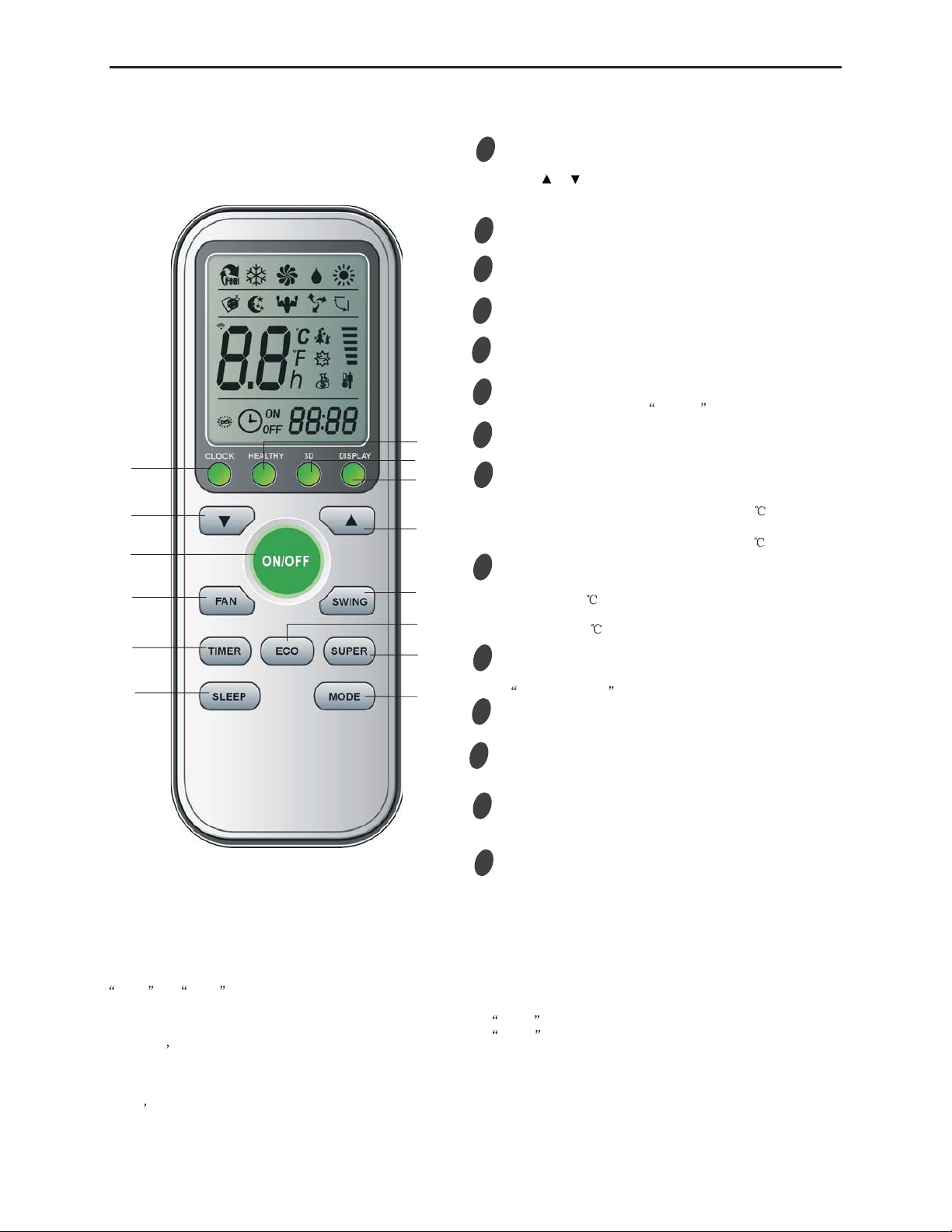
Remote Control
Note :
The remote controller is not presetting as Cooling Only Air Conditioner or Heat Pump by manufacturer.
Each time after the remote controller replace batteries or is energized, the arrowhead will flashes on the front of
Heat or Cool on LCD of the remote controller.
User can preset the remote controller type depending on the air conditioner type you have purchased as follows:
Press any button when the arrowhead flashes on the front of Cool , Cooling Only is set.
Press any button when the arrowhead flashes on the front of Heat , Heat Pump is set.
If you don t press any button within 10 seconds, the remote controller is preset as Heat Pump automatically.
If the air conditioner you purchased is a Cooling Only one, but you preset the remote controller as Heat Pump, it
doesn t bring any matter. But if the air conditioner you purchased is a Heat Pump one, and you preset the remote
controller as Cooling Only, then you CAN NOT preset the Heating operation with the remote controller.
Remote controller 1
2
4
3
5
6
9
7MODE button
ECO button
ON/OFF button
FAN SPEED button
TEMP UP button
TIMER button
SLEEP button
TEMP DOWN button
To select the mode of operation.
In cooling mode,press this button ,the temperature
will increase 2 on the base of setting temperature:
In heating mode, press this button, the temperature
will decrease 2 on the base of setting temperature.
To switch the conditioner on and off.
To select the fan speed of auto/low/mid/high.
To set automatic switching-on/off.
Increase the temperature or time by 1 unit.
To activate the function SLEEP .
Decrease the temperature or time by 1 unit.
4.Operation Details
8SUPER button
In cooling mode, press this button, the unit will give
the maximum cooling temperature with 16
In heating mode, press this button, the unit will give
the maximum heating temperature with 31 .
9
SWING button
10
To activate or deactivate of the movement of the
DEFLECTORS .
12 DISPLAY button
To LED display (if present).switch on/off the
9
3
4
2
1
9
5
67
8
10
11
12
9
CLOCK
11
Press this button to set the time. When the time is flashing,
press !or !to adjust the time. Every press equals one
minute,or press and hold for rapid adjustment. Press
CLOCK again once the time has been set.
.
13
14
12 3D
9
13
When you press "3D", the horizontal and vertical
vanes will swing together at the same time.
12
14 HEALTHY button
To switch - on /off HEALTHY function. It is a button
which controls the ionizer or plasma generator only
for inverter type.
4
Air Conditioner Service Manual
Electronic Controller
1. Safety Protection
(1) Time Delay for Safety protection
3 minutes delay for compressor ---The compressor is ceased for 3minutes before restarting to
balance the pressure in the refrigeration cycle in order to protect the compressor.
2 minutes delay for 4-way valve---The 4-way valve will be ceased for 2 minutes late after
compressor to prevent the refrigerant-gas abnormal noise when the HEATING
operation is
OFF or switch to the other operation mode.
(2) Discharge temperature protection
There is a temperature sensor on top of compressor, when temperature on top of
compressor
exceeded the limit, system control will shut down the compressor and the display board will
show the error code.
(3) Lower voltage protection
When AC voltage 158V and keep it for 10 seconds, unit will be shut down for protection.
(4) Over voltage protection
When AC voltage 260V, unit will be shut down and recover while AC255V.
(5) Over current protection
When the current of outdoor unit is overload, controller shut down the unit immediately and show
error code.
(6) Compressor abnormity protection
When compressor start on or in the process of running, if there is no feedback to controller or
load of compressor is abnormity, the air conditioner will shut down, and show error code.
(7) IPM module protection
IPM module has high temperature & over current protection itself, if there is signal feedback to
IPM, the outdoor unit will shut down, LED on outdoor PCB will show the error code.
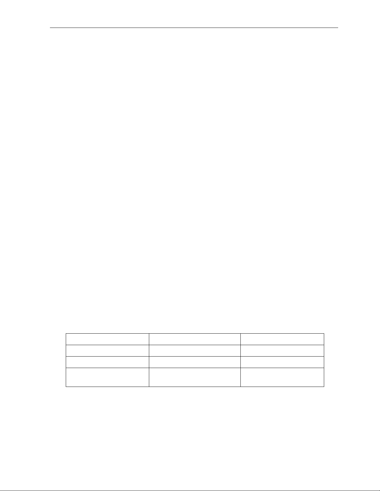
2. “Feel” Mode Operation
(1) When the “Feel” mode is selected, the operation mode and initial temperature set are
determined by the initial room temperature at start-up of the operation except to turn off the air
conditioner and operates it again.
(2) If the mode is change to “Feel” from other mode, the “Feel” mode doesn’t operate until
compressor stop for more than 3 minutes.
Mode Initial Room Temperature Initial Set Temperature
COOLING RT=26 23
DRY 26RT20 RT-2
HEATING for Heat Pump/
FAN for Cooling Only RT<20 -
In the “Feel” mode, when the controller receives the up or down signal of temperature,
the set
temperature can adjust by 1 upper or lower. The biggest you can adjust by 2 upper or lower.
3. “COOLING” Mode Operation
(1) Compressor frequency control
According to difference room temperature and set temperature (δt = RT-ST), running frequency of
compressor is controlled by electronic controller. When room temperature is much higher than set
temperature, the compressor will start at a high frequency, and as room temperature goes down, the
compressor running frequency will go down. When room temperature is lower than set temperature,
5
thecompressor will run at very low frequency. In general, unit will change its running frequency
according toδt to make room temperature closing to set temperature.
(2) Outdoor temperature affects running frequency of the compressor
Outdoor temperature affect compressor’s running frequency. Difference inlet temperature of
outdoor unit is adapted by difference compressor running frequency. While outdoor temperature is
about 30, the compressor will run in high frequency.
If unit run in “cooling” mode and outdoor temperature is less than -2,the controller will shut down
compressor and show error code, while the ambient temperature is over 1, the compressor will run
automatically.
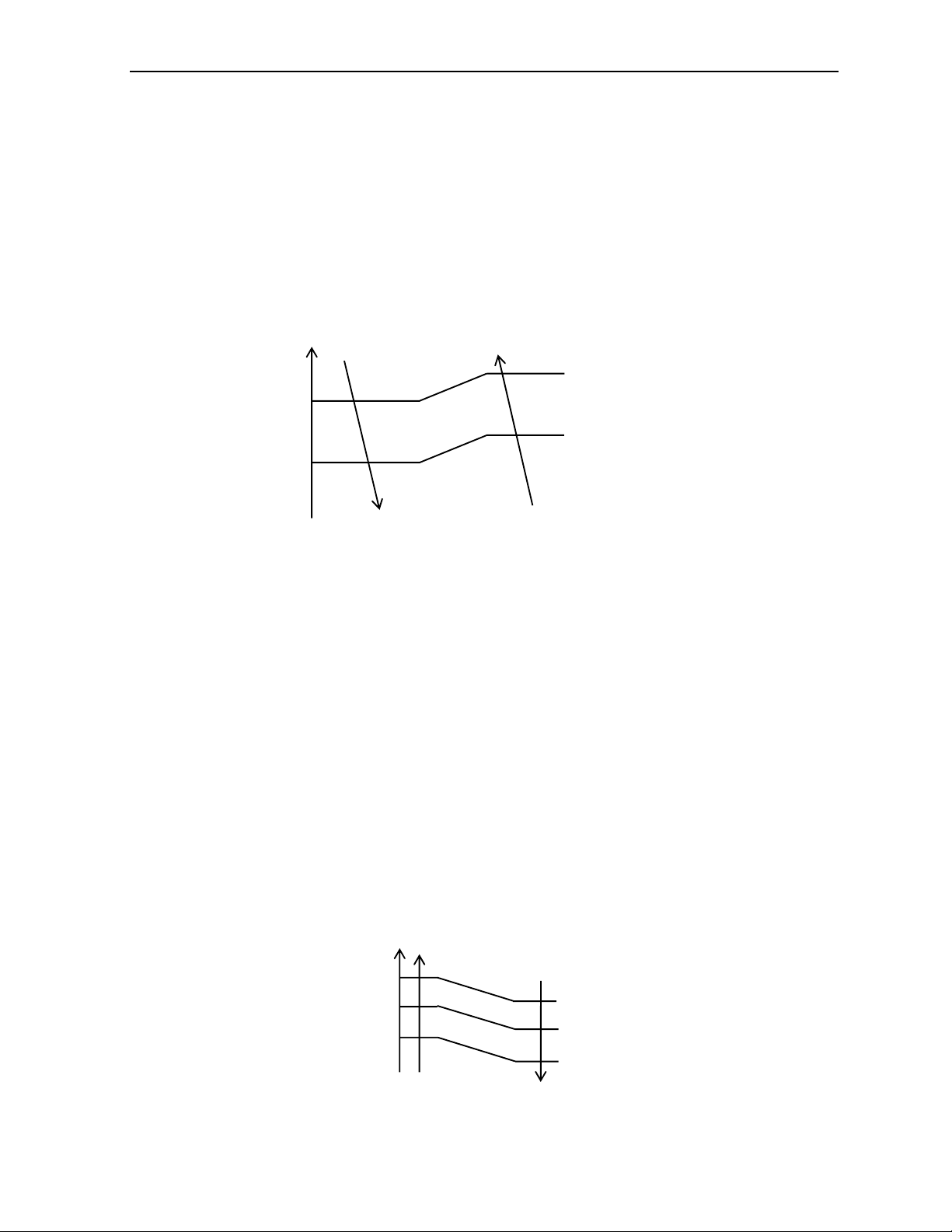
(3) Auto fan control in cooling mode
In cooling mode (include cooling in “feel” mode), fan speed is determined by
t, as the following
diagram:
4.“DRY” Mode Operation
(1) The system for DRY operation used the same refrigerant circle as the cooling one.
(2) When the system operates in DRY mode, at first it operates in cooling mode, the set
temperature (ST) is “RT-2”. After that, t he system will operate in cooling mode with lowest
fan speed for 30 minutes and then change to middle speed for 30seconds as a cycle. During
the course of this operation, you can’t use remote controller to adjust the fan speed but you can
control the vane direction.
(3) In the dry mode, when RT12
5. “HEATING” Mode Operation (available for Heat Pump only)
(1) Frequency control
Same as the frequency control in cooing mode, the running frequency of compressor is
controlled by controller. Unit change its running frequency according to
t to make the room
temperature closing to the set temperature.
(2) Indoor fan motor control
1) Cold Air Prevention Control
The function is intended to prevent cold air from being discharged when heating mode
selected or while in defrosting.
The indoor fan speed will be controlled as following.
In heating operation, if air conditioner turn off, the indoor fan motor will run most for 30
RTST
t come down
t come up
High fan
Min fan
Low fan
Breeze
Temp erat u re u p
Temp erat u re d o wn
Setting
Low fan
Stop
37
33
25
34
28
22
Air Conditioner Service Manual
6
Air Conditioner Service Manual
seconds since the stop of compressor.
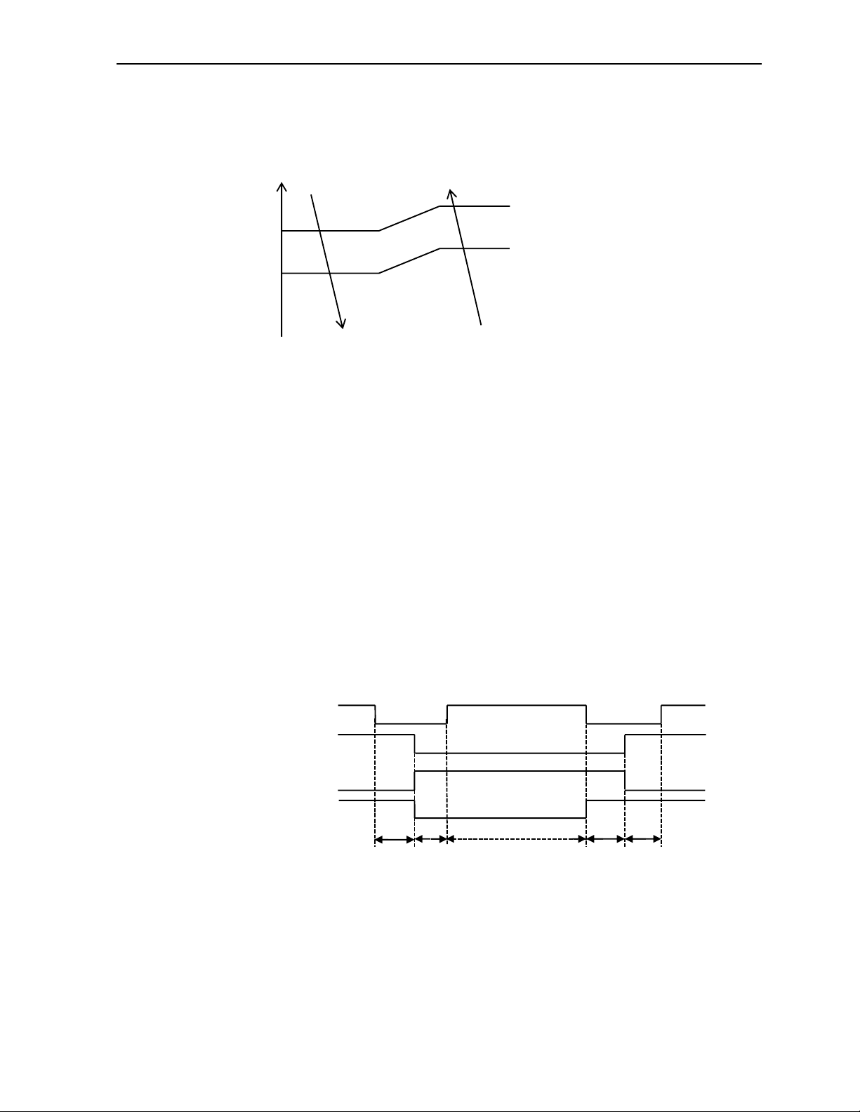
2) Auto fan control (heating)
In heating mode (include in “I feel” mode) , fan speed is determined by t as the following:
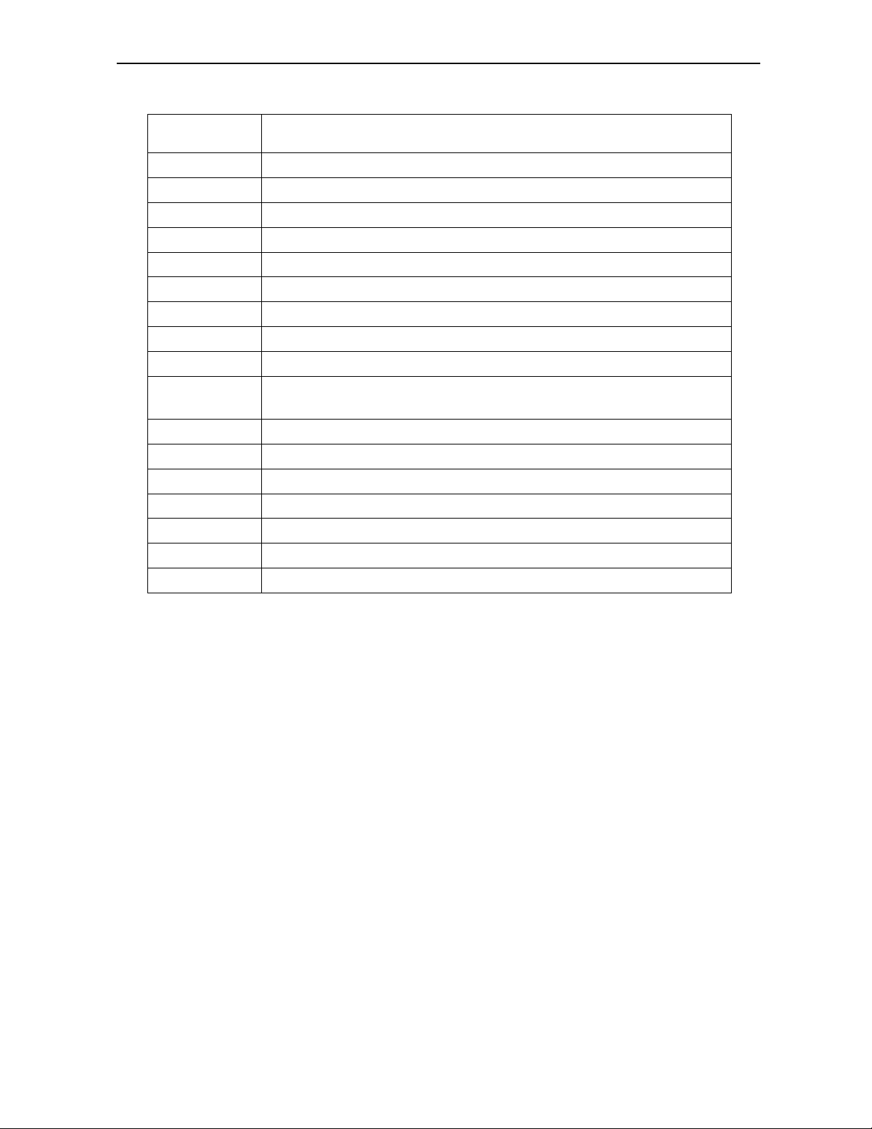
(3) 4-way valve control
In heating mode, 4-way valve will power on ahead of compressor for 5 seconds, and cut off
for 2 minutes later than compressor. 4-way valve will not power off unless the machine to be
switched off, mode changed or on the process of defrosting.
(4) Defrosting
Defrosting is controlled by the microprocessor.
When one of the following conditions is satisfied, unit comes into defrosting:
a.
Outdoor heat exchanger Temperature (OPT) is continuously less than 3 while the unit runs
for more than 40 minutes, and OPT is keeping under -6 for more than 3 minutes.
b.
Outdoor heat exchanger Temperature (OPT) is continuously less than 3 meanwhile the
unit runs for more than 80 minutes, and OPT is keeping under -4 for more than 3
minutes.
c.
Outdoor heat exchanger Temperature (OPT) is continuously less than 3 while the unit runs
for more than 120 minutes, and OPT is keeping below -2 for more than 3 minutes.
Before the air con comes into defrosting, compressor running frequency drop down to a
lower frequency firstly, then the compressor shuts down.
In defrosting, the max. frequency of compressor is F9 (a little less than the highest
frequency ). In this period all protection function are available.
In defrosting, LED showing by winking.
No matter what AC come into or out of defrosting, indoor fan motor speed is the same as Cold
Air Prevention Control.
While one of the following conditions is satisfied, unit comes out of defrosting and shifts to
heating mode:
a.
Outdoor coil Temperature (OPT) ≥15
b.
The time of defrosting keeps for more than 10 minutes.
(5) Indoor exchanger overheat protection
When Indoor exchanger Temperature (IPT) is higher than 55 , unit comes into indoor exchanger
RTST
t come down
t come up
High fan
Min fan
Low fan
Compressor ON
OFF
ON
OFF
ON
OFF
NORMAL 800
4-way valve
Expansion valve
Outdoor fan motor
50S 10Mins 15S 15S
10S
7

Air Conditioner Service Manual
overheat protection. The compressor drops its frequency toward to F1 level until IPT≤52
If IPT≤52 and keep for 5 minutes, control system doesn’t limit running frequency.
If IPT>62, control system shut down compressor, and recover while IPT drop less than 50.
6. “SLEEP” mode
When the SLEEP button is pressed, the AC operates as following:
The indoor fan speed is set at low speed, the power lamp and the sleep lamp is on, the
display of temperature will close after 5 minutes.
When selecting COOLING/DRY operation with SLEEP mode, the set temperature will be
raised by 1 1 hour later and by 2 2 hour later.
When selecting HEATING operation with SLEEP mode, the set temperature will be dropped by
11 hour later and 2 2 hours later.
After the System operates in SLEEP mode for 8 hours, it will stop automatically.
7. EMERGENCY Operation
When the EMERGENCY Operation switch is pressed one time, COOLING mode is selected
and if the EMERGENCY Operation switch press again within 3s, HEATING mode selected, while
press once again, the unit will switch off.
When the remote controller missing, failed or the batteries run down, press the EMERGENCY
Operation switch on front of the indoor unit for function test.
NOTE: Do not press the EMERGEMCY Operation switch during normal operation.
8. AUTO-RESTART Function (Option)
While air conditioner is operating in one mode, all of its operation data, such as working mode,
preset temperature etc. would be memorized into IC by main PCB. If power supply cut off due to
reasons and recover again, the AUTO-RESTART function will set
synchronously and the air
conditioner would work at the same mode as before.
Auto-restart Pre-setting (optional):
If Auto-restart function is needed, follow the steps below to activate this function:
1) Pulling the air-con's plug out of socket.
2) Pressing and holding the Emergency button (ON/OFF) on the indoor, then insert the plug
into the socket again.
3) Keep pressing the Emergency button for more than 10 seconds until three short beeps
heard, the Auto-restart function been activated.
9. Protection and Failure Display
When protection display is available, controller will show error code, digital LED shows
error code and setting temperature by turns.
If there is more than one failure, it will show error codes according to the error list sequence.
To i n s u r e t h e s i g n a l c o m m u n i c a t i o n o f i n d o o r and outdoor unit, any failure code relates to
outdoor unit will remain display for 2 minutes maximum after it’s recovered.
Among all the failure codes, sensor failure can be recovery automatically once it comes normal.
8

Air Conditioner Service Manual
Error list
Failure Type
LED Code Digital LED Code
Indoor and outdoor communication failure RUN、TIMER –both winking E0
Outdoor communication failure RUN、TIMER –both winking EC
Indoor room temperature sensor (IRT) RUN-1 time/8s E1
Indoor coil temperature sensor (IPT) RUN-2 times /8s E2
Outdoor coil temperature sensor (OPT) RUN-3 times /8s E3
System abnormity RUN-4 times /8s E4
Model configuration wrong RUN-5 times /8s E5
Indoor fan motor fault RUN-6 times /8s E6
Outdoor temperature sensor RUN-7 times /8s E7
Exhaust temp. sensor RUN-8 times /8s E8
IPM drive and module fault RUN-9 times /8s E9
Outdoor fan motor fault (DC motor) RUN-10 times /8s EF
Current sensor fault RUN11 times /8s EA
Indoor unit EEPROM fault RUN-12 times /8s EE
Temp. switch fault ( on top of the
compressor)
RUN-13 times /8s EP
Voltage sensor fault RUN-14 times /8s EU
Protection display code list:
Outdoor failure display
There is a LED on outdoor power board, it blinks 1s ON and 1s OFF while compressor standby and it
always light (ON) while compressor running; If there is failure happened on ODU,The indicator (LED)
alerts the fault in a cycle as such that it is bright for 0.5 seconds, dark for 0.5 seconds, blinks “n” times
and then dark for 3 seconds. For details as table below:
Protection Type Function Indicator (flash) Digital LED Code
Overvoltage /lower voltage protection RUN: Blink; TIMER: 1 blink /8 sec P1
Overcurrent protection RUN: Blink; TIMER: 2 blink /8 sec P2
Exhaust over temperature protection RUN: Blink; TIMER: 4 blink /8 sec P4
Too cool protection in cooling mode RUN: Bright; TIMER: 5 blink /8 sec P5
Overheat protection in cooling mode RUN: Bright; TIMER: 6 blink /8 sec P6
Overheat protection in heating mode RUN: Bright; TIMER: 7 blink /8 sec P7
Outdoor over temperature
/ lower temperature protection RUN: Bright; TIMER: 8 blink /8 sec P8
Drive protection (software control ) RUN: Blink; TIMER: 9 blink /8 sec P9
Module protection (hardware control) RUN: Blink; TIMER: 10 blink /8 sec P0
9
blink time (n)
Failure
1 IPM protection
2 Over voltage /lower voltage
3 Overcurrent
4 Exhaust over temperature protection
5 Outdoor coil over temperature protection
6 Drive fault and protection (V1,VP1)
7 Communication fault with indoor unit
8 Compressor overheat fault (compressor top switch)
9 Short-circuit / open-circuit fault of outdoor temperature sensor
10 Short circuit / open-circuit fault of outdoor heat exchanger temperature
sensor
11 Short-circuit / open-circuit fault of exhaust temperature sensor
12 Voltage sensor fault
13 Current sensor fault
14 IPM fault
15 Communication fault between power source board and IPM
16 No feedback from DC fan motor(outdoor unit)
17 Defrost state
Display on outdoor power source board:
Air Conditioner Service Manual
10
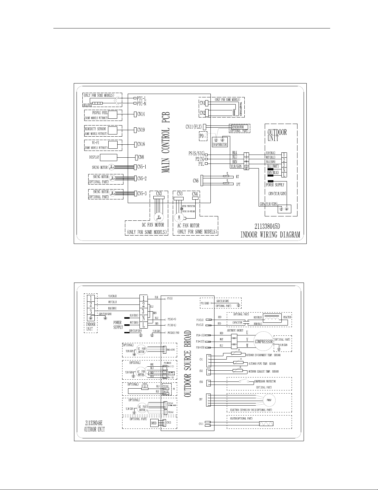
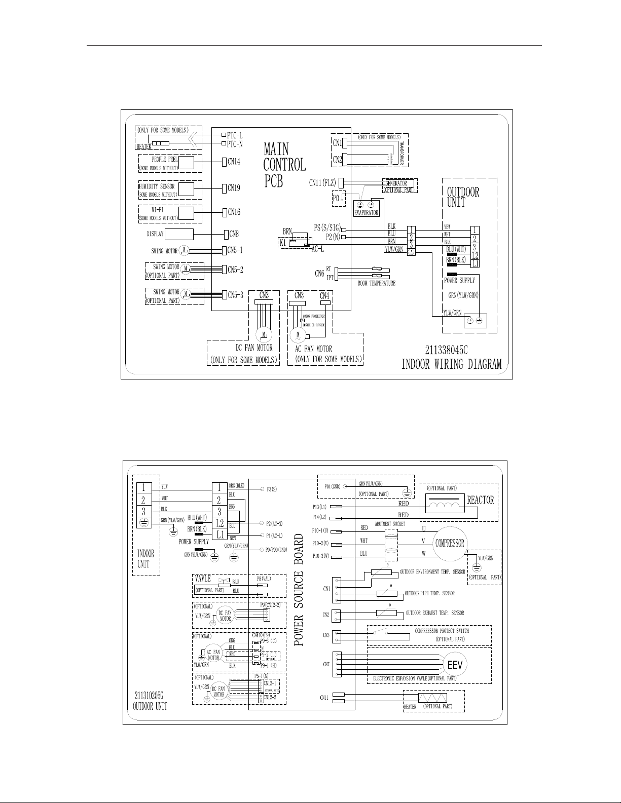
5. Wiring diagram
OUTDOOR UNIT
INDOOR UNIT:
Mode: MGTC0913E-20 /MGTC0913C-20
Air Conditioner Service Manual
11
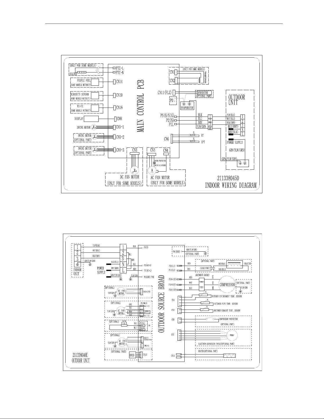
Air Conditioner Service Manual
OUTDOOR UNIT
INDOOR UNIT
Mode:MGTC0923E-20 /MGTC0923C-20
12
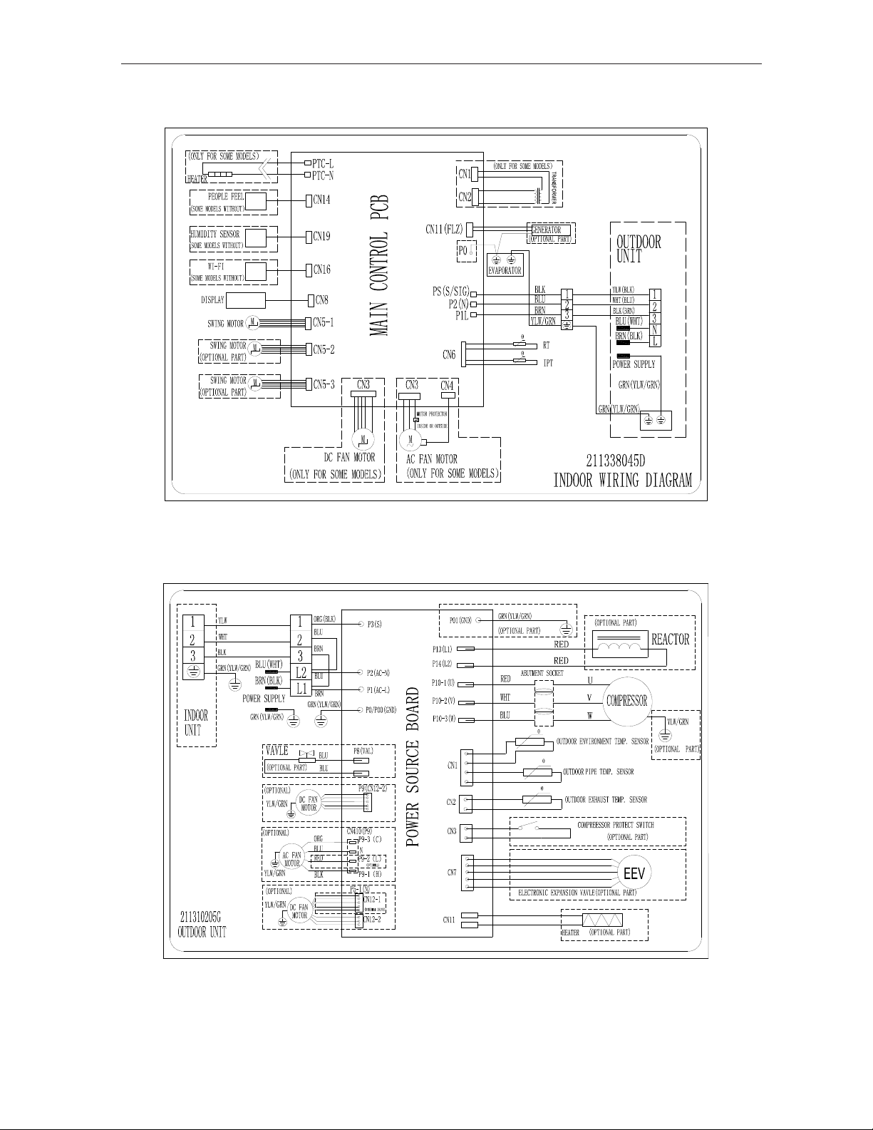
Air Conditioner Service Manual
M•:MGTC1213E-20 /MGTC1213C-20
INDOOR UNIT
OUTDOOR UNIT
13
MODEL: MGTC1223E-20 /MGTC1223C-20
14
Air ConditionerService Manual
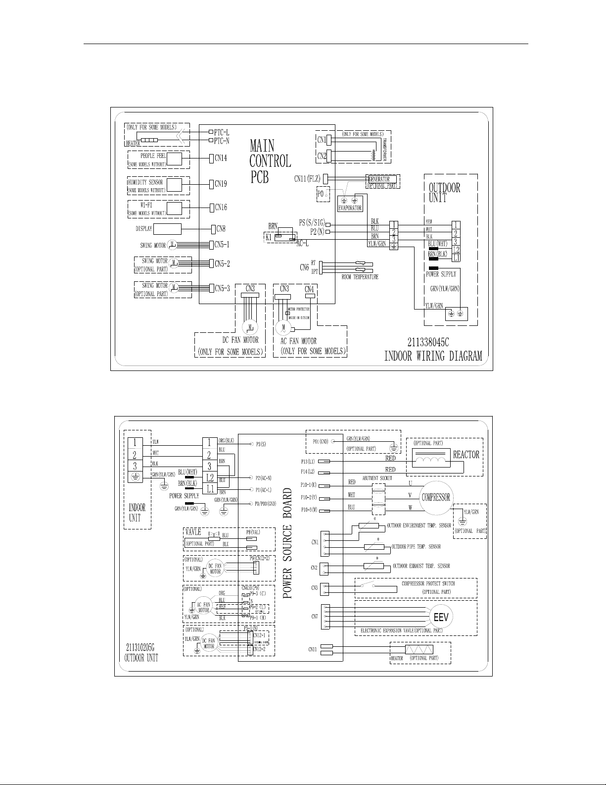
MODEL: MGTC1823E-20 /MGTC1823C-20MGTC2423E-20 /MGTC2423C-20,
MGTC3623E-17 /MGTC3623C-17
15

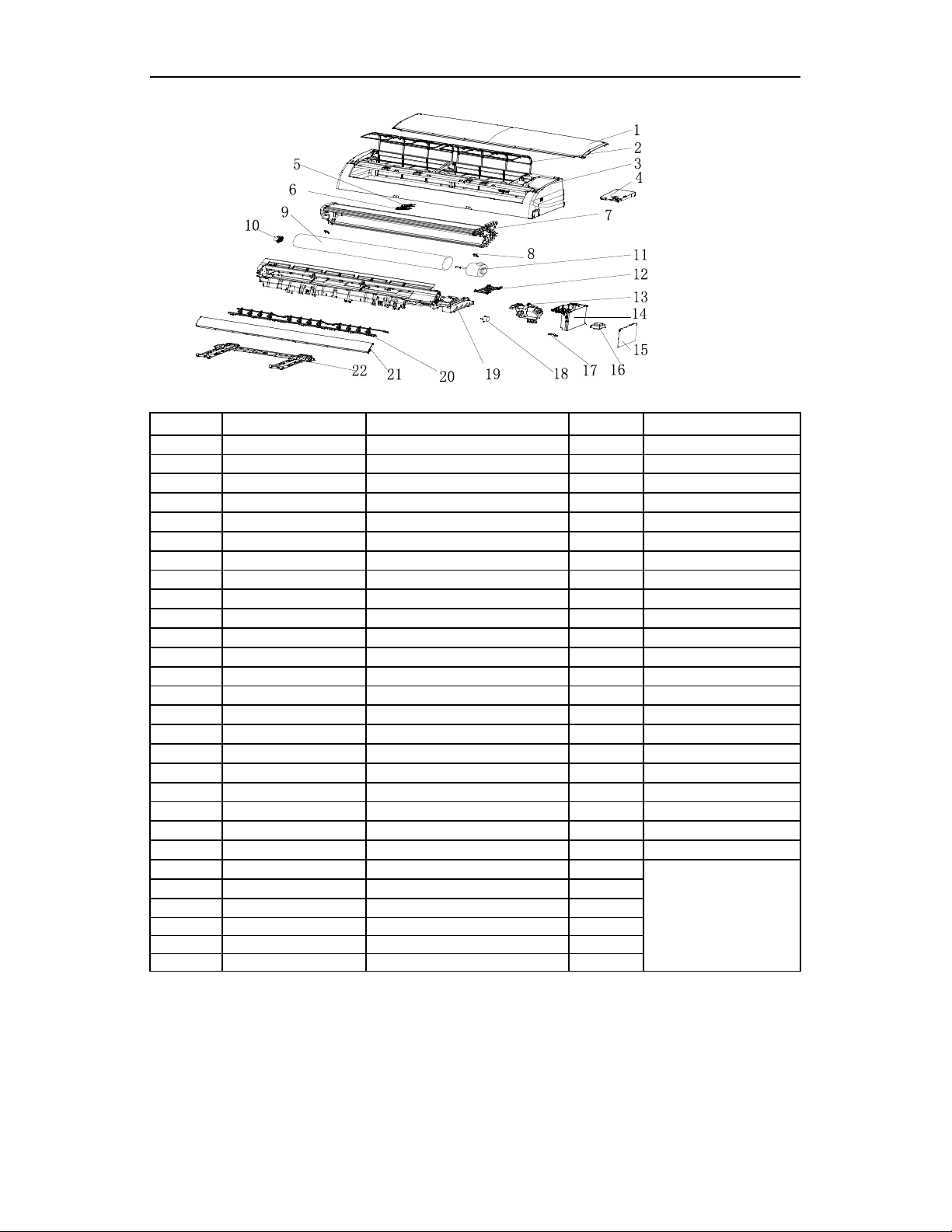
6. Explosion view and parts
Indoor Unit- G4BMV00000 KFR-26G/YXABp(E1/6)(BMV00)
No. Part No. Part Name Q’ty Remark
1FrontPanel1
2AirFilter 2
3FaceFrame1
4ElectricalBoxCover1
5DisplayPCB1
6DisplayPCBBox1
7Evaporator1
8ScrewCover2
9CrossFan1
10 Bearing Mount 1
11 Indoor Motor 1
12 In And Out Pipe Fixer 1
13 Indoor Motor Cover 1
14 Electrical Box 1
15 Main PCB 1
16 Transformer 1
17 Cable Clamp 1
Vane Motor 1 1
Vane Motor 2 1
19 Base 1
20 Vertical Vane Assembly 2
21 Vane 1
22 Installation Plate 1
23 Indoor Sensor Assembly 1
24 Remote Controller 1
25 wifi 1
26 Draina
g
e Hose 1
27 Indoor Carton 1
28 Left Foamin
g
1
29 Ri
g
ht Foamin
g
1
Air Conditioner Service Manual
18
Not shown in Explosion
view
16
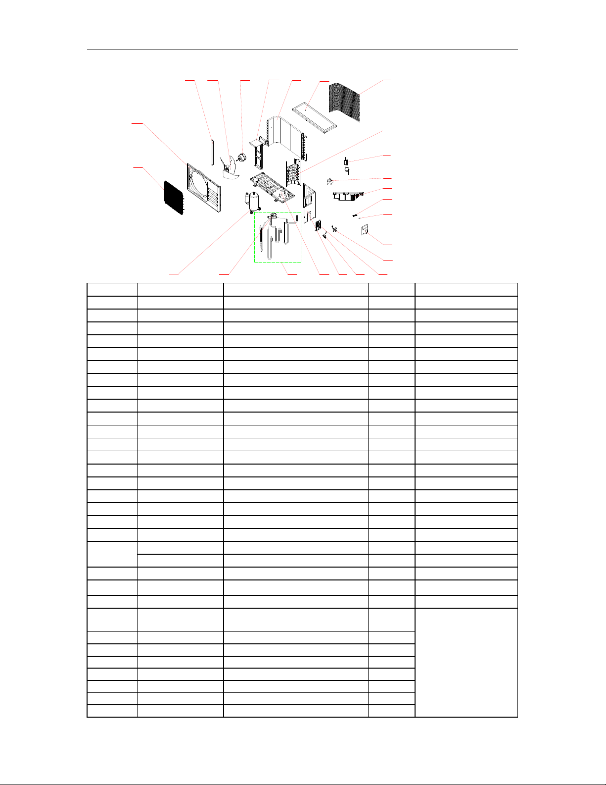
No. Part No. Part Name Q’ty Remark
1Grille 1 Optional
2Top Cover 1
3Condenser 1
4Outdoor Motor Supporter 1
5Outdoor Motor 1
6Propeller Fan 1
7Left grille supporter 1
8Front Plate 1
9Fan Guard 1
10 Compressor 1
11 4-way Valve 1
12 4-way Valve Assembly 1
13 Base 1
14 Right Plate 1
15 Two-way Valve 1
16 Valve Supporter 1
17 Three-way Valve 1
18 Electrical Box Cover 1
19 Terminal 1
20 Cable clamp1 1
21 Outdoor PCB Assembly 1
22 Inductor 1
23 Capillary Assembly 1
24 Partition plate 1
25 Pipe Temp. sensor and outdoor
Temp. sensor 1
26 Discharge Temp. sensor 1
27 Compressor Capacitor 1
28 Capacitor Strip 1
29 Base carton 1
30 Cabinet carton 1
31 Base foaming 1
32 Cover foaming 1
Air Conditioner Service Manual
Outdoor Unit- G5BBW00000 KFR-26W/YXABp(E1/6)(BBW00)
Not shown in explosion
view
10 11 12
8
9
765
17
13 14 16
15
19
18
20
21
23
22
4321
24
17
Indoor Unit- MGTC0923E-20
No. Part No. Part Name Q’ty Remark
141106-003591 FrontPanel 1
242008-000039 AirFilter 2
341106-002375 FaceFrame 1
441211-000077 ElectricalBoxCover 1
531102-000084 DisplayPCB 1
642003-000001 DisplayPCBBox 1
792011-004784 Evaporator 1
841108-000066 ScrewCover 2
942004-000001 CrossFan 1
10 42007-000001 Bearing Mount 1
11 22001-000267_UM Indoor Motor 1
12 41101-000242 In And Out Pipe Fixer 1
13 42003-000051 Indoor Motor Cover 1
14 41105-000134 Electrical Box 1
15 31101-000247_UM Main PCB 1
16 NO Transformer 1
17 42001-000103 Cable Clamp 1
18 22001-000313 Vane Motor 1 1
19 41102-000091 Base 1
20 41101-000082 Vertical Vane Assembly 2
21 41103-000102 Vane 1
22 41109-000041 Installation Plate 1
23 10104-100014 Indoor Sensor Assembly 1
24 22013-000946 Remote Controller 1
25 32001-000057 Wifi 1
26
A
1101-007281 Indoor Carton 1
27 41110-000217 Left Foamin
g
1
28 41110-000262 Ri
g
ht Foamin
g
1
Air Conditioner Service Manual
Not shown in Explosion
view
18
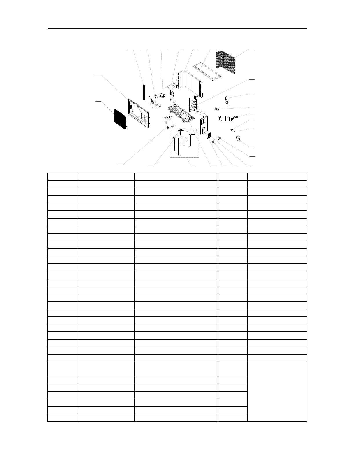
Outdoor Unit- MGTC0923C-20
No. Part No. Part Name Q’ty Remark
142011-000184 Grille 1
241207-000029 Top cover 1
392011-000777 Condenser 1
441203-000054 Outdoor motor supporter 1
522001-000049_UM Outdoor motor 1
642004-000107 Propeller fan 1
741205-000121 Left grille supporter 1
841206-000052 Front plate 1
942011-000038 Fan guard 1
10 92014-000142 Compressor and accessories 1
11 92008-000209 4-way valve 1
12 92007-000969_UM 4-way valve assembly 1
13 41202-000216 Base 1
14 41205-000083 Right plate 1
15 92007-001050 Two-way valve 1
16 41204-000018 Valve supporter 1
17 92007-001041_UM Three-way valve 1
18 41201-000044 Eelectronic Box Cover 1
19 42001-000036 Cable clamp 1
20 11304-100045_UM Terminal 1
21 31201-000988_UM Outdoor PCB Assembly 1
22 22011-000002_UM Inductor 1
23 92007-002083 Capillary assembly 1
24 41208-000141 Partition plate 1
25 10104-100047 Pipe Temp. sensor and outdoor
Temp. sensor 1
26 10104-100036 Discharge Temp. sensor 1
27 41204-000051 Valve cover 1
28 A2005-000530 Base carton 1
29 A1201-007955 Cabinet carton 1
30 A1202-000039 Base foaming 1
31 41213-000030 Cover foaming 1
Air Conditioner Service Manual
Not shown in explosion
view
10 11 12
8
9
765
17
13 14 16
15
19
18
20
21
23
22
4321
24
19
This manual suits for next models
13
Table of contents
Other Everwell Air Conditioner manuals


Popular Air Conditioner manuals by other brands

Sanyo
Sanyo KS2432 instruction manual

Mitsubishi Electric
Mitsubishi Electric Mr.Slim MSZ-A24NA operating instructions

Rotenso
Rotenso MIRAI W user manual

Mitsubishi Electric
Mitsubishi Electric Mr.SLIM MS24WN Service manual

Haier
Haier 2HUM14HC03-R2 installation manual

Friedrich
Friedrich Chill CP18 Installation and operation manual


