Everwell METH-16 Operating manual

METH-16 - USER AND INSTALLATION MANUAL
METH-16
Julio 2021
C O NT E N T S
SA F E T Y PR E C A UT I ONS
NA ME S OF PA RT S
INDOOR UNIT DISPL AY
OPE R ATI NG INST R UCT IONS
PR OT E CT I ON
INSTAL L ATION MANUAL
MA I NT E NA NC E
T R OUB L E SHOOT I NG
E ME R G E NC Y FU NC TI ON & A UT O-R E STA RT FUNC T ION
R E M OT E C ONT R OL L E R
....................................................................................................1
.................................................................................................................4
.........................................................................................................5
..............................................6
........................................................................................................7
.............................................................................................11
.........................................................................................................................16
....................................................................................................17
....................................................................................................................26
..........................................................................................................27
METH-16

During the installation of the indoor and
outdoor units the access to the working area
should be forbidden to children.
Unforeseeable accidents could happen.
Make sure that the base of the outdoor unit is
rmly xed.
Check that air cannot enter the refrigerant
system and check for refrigerant leaks when
moving the air con ditioner.
SAFETY RULES AND RECOMMENDA TIONS FOR THE INSTALLER
Carry out a test cycle after installing the air
conditioner and record the operating data.
The ratings of the fuse installed in the built
incontrol unit are T 5A / 250V .
The user must protect the indoor unit with a
fuse of suitable capacity for the maximum input
current or with another overload protection
device.
Ensure that the mains voltage corresponds to
that stamped on the rating plate. Keep the switch
or power plug clean. Insert the power plug
correctly and rmly into the socket, thereby
avoiding the risk of electric shock or re due to
insucient contact.
Check that the socket is suitable for the plug ,
otherwise have the socket changed.
Do not install the appliance at a distance of
less than 50 cm from inammable substances
(alcohol, etc.) Or from pressurised containers
(e.g. spray cans).
If the appliance is used in areas without the
possibility of ventilation, precautions must be
taken to prevent any leaks of refrigerant gas
from remaining in the environment and creating
a danger of re
The packaging materials are recyclable and
should be disposed of in the separate waste
bins .Take the air conditioner at the end of its
useful life to a special waste collection centre
for disposal.
Only use the air conditioner as instructed in
this booklet. These instructions are not intended
to cover every possible condition and situation .
As with any electrical household appliance ,
common sense and caution are therefore always
recommended for installation, operation and
maintenance.
The appliance must be installed in accordance
with applicable national regulations.
Before accessing the terminals , all the power
circuits must be disconnected from the power
supply.
Read this guide before installing and using the
appliance.
1
T
he appliance must be tted with meansfor
disconnection fromthe supply mains having a
contact separation inall poles that provide full
disconnection under overvoltage category III
conditions, and these means must be incorporated
in the xed wiring in accordance with the wiring
rules.
The appliance shall be installed in accordance
with national wiring regulations.
This appliance can be used by children aaged
from 8 years and above and persons with
reduced physical, sensory or mental capabilities
or lack of experience and knowledge if they
have been given supervision or instruction
concerning use of the appliance in a safe way
and understand the hazards involved. Children
shall not play with the appliance. Cleaning and
user maintenance shall not be made by
children without supervision.
The air conditioner must be installed by
professional or qualied persons.

SAFETY RULES AND RECOMMENDA TIONS FOR THE USER
Do not try to install the conditioner alone;
always contact specialized technical personnel.
Cleaning and maintenance must be carried out
by specialised technical personnel. In any case
disconnect the appliance from the mains
electricity supply before carrying out any
cleaning or maintenance.
Ensure that the mains voltage corresponds to
that stamped on the rating plate. Keep the switch
or power plug clean. Insert the power plug
correctly and rmly into the socket , thereby
avoiding the risk of electric shock or re due
to insucient contact.
Do not pull out the plug to switch o the
appliance when it is in operation, since this
could create a spark and cause a re, etc.
If the appliance gives o smoke or there is a
smell of burning, immediately cut o the pow
er supply and contact the Service Centre.
Have repairs carried out only by an authorised
Service Centre of the manufacturer . Incorrect
repair could expose the user to the risk of
electric shock, etc.
The prolonged use of the device in such
conditions could cause re or electrocution.
N
ever remain directly exposed to the ow of
cold air for a long time.The direct and prolonged
exposition to cold air could be dangerous for your
health .Particular care should be taken in the
rooms where there are children , old or sick
people.
This appliance has been made for air
conditioning domestic environments and must
not be used for any other purpose , such as for
drying clothes, cooling food, etc.
The packaging materials are recyclable and
should be disposed of in the sparate waste
bins . Take the air conditioner at the end of its
useful life to a special waste collection centre
for disposal.
Only use the air conditioner as instructed in
this booklet.These instructions are not int ended
to cover every possible condition and situation.
As with any electrical household appliance,
common sense and caution are therefore always
recommended for installation , operation and
maintenance.
Always use the appliance with the air lter
mounted . The use of the conditioner without
air lter could cause an excessive accumulation
of dust or waste on the inner parts of the device
with possible subsequent failures.
Unhook the automatic switch if you foresee
not to use the device for a long time.
The airow direction must be properly adjusted.
T
he user is responsible for having the appliance
installed by a qualied technician , who must
check that it is earthed in accordance with current
legislation andinsert a thermomagnetic circuit
breaker.
Ensure that the appliance is disconnected from
the power supply when it will remain inoperative
for a long period and before carrying outany
cleaning or maintenance.
Selecting the most suitable temperature can
prevent damage to the appliance.
The aps must be directed downwards in
the heating mode and upwards in the cooling
mode.
The batteries in remotecontrollermust be
recycledor disposed ofproperly.
Disposal of Scrap Batteries --- Please discard
the batteries assortedmunicipalwaste at the
accessiblecollectionpoint.
2

SAFETY RULES AND PROHIBITIONS
3
Do not bend , tug orcompress the power cord
since this could damage it. Electrical shocks or
re are probably due to a damaged power cord.
Specialised technical personnel onlymust replace
a damaged powercord.
Do not use extensions or gang modules.
Do not touch the appliance when barefoot or
parts of the body are wet or damp.
Do not obstruct the air inlet or outlet of the
indoor or the outdoor unit.
The obstruction of these openings causes a
reduction in the operative eciency of the
conditioner with possible consequent failures
or damages.
In no way alter the characteristics of the
appliance.
Do not install the appliance in environments
where the air could contain gas , oil or sulphur
or near sources of heat.
Do not climb onto or place any heavy or hot
objects on top of the appliance.
Do not leave windows or doors open for long
when the air conditioner is operating.
Do not direct the airow onto plants or
animals.
Along direct exposition to the ow of cold
air of the conditioner could have negative
eects on plants and animals.
Do not put the conditioner in contact with
water.
The electrical insulation could be damaged
and thus causing electrocution.
Do not climb onto or place any objects on the
outdoor unit
Never insert a stick or similar object into the
appliance. It could cause injury.
T
his appliance is not intendedfor use by
persons (including children ) with reduced
physical, sensory or mental capabilities, or
lack of experience and knowledge, unlessthey
have beengiven supervision or instruction
concerninguse of theapplianceby a person
responsible for their safety.
C
hildren should be supervised to ensure
that they do not play with the appliance.
If the supply cord is damaged, it must be
replaced by the manufacturer,its service
agent or similarly qualied persons in
order to avoida hazard.

NAMES OF PARTS
No. Description
1
2
Front panel
Air lter
Optional lter (if installed)
3
Terminal block cover
4
Emergency button
5
6
LED Display
Signal receiver
7
Airow direction louver
8Deectors
9
Remote controller
10
Note: the above gures are only intended to be a
simple diagram of the appliance and may not
correspond to the appearance of the units that
have been purchased.
No. Description
13 Air outlet grille
Terminal block cover
14
gas valve
15
liquid valve
16
11
Indoor unit rating label ( )Stick position optional
17
Outdoor unit rating label
12
Ionizer (if installed)generator
13
15
16
17
INDOOR UNIT
4
OUTDOOR UNIT
12-3
6
4-5
9
11 8
10 7
14
DISPLAY HE AL TH Y3D
ON/OFF
SWING
FAN
TIMERSU PE R
SLEE PMODE
ECO
CLOCK
12
INDOOR UNIT
OUTDOOR UNIT
10
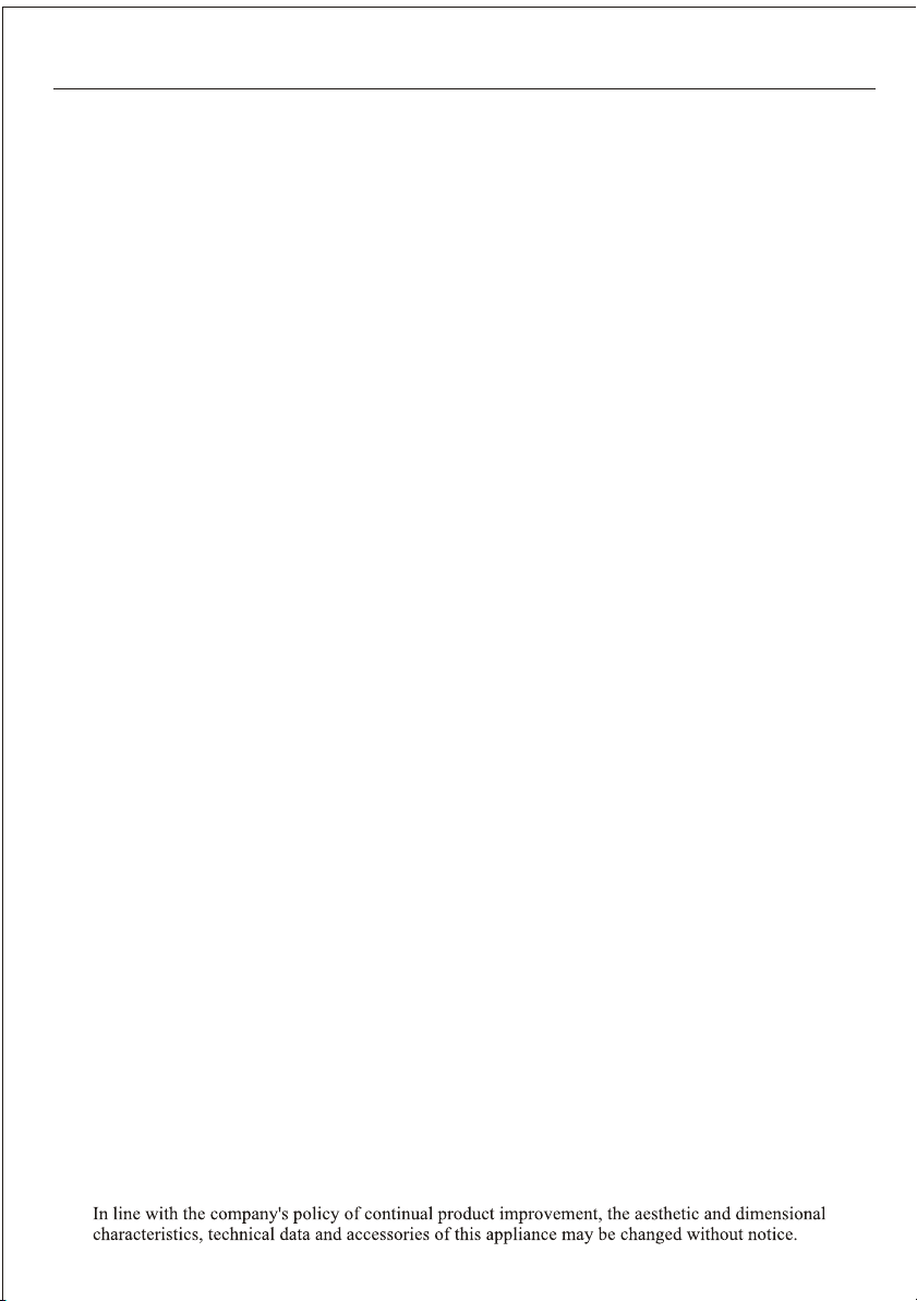
INDOOR UNIT DISPLA Y
1
2
5
3
4
1 2 345
The shape and position of switches and indicators may be dierent according to the model, but their
function is the same.
12 4 5
3
5
1
2
3
4
5
3
12
3
54
No.
Led Function
POWER This symbol appears when the unit is power on
1
2
3
4
5
Temperature display (if present)
/Error code
(1) Lights up during Timer operation when
the air conditioner is operational
(2)Displays the malfunction code when fault
occurs.
SLEEP mode
Lights up during Timer operation.
The symbol appears when the unit is turned
on, and disappear when the unit is turned o.
SLEEP
TIMER
RUN
3
4
2
1245

EMERGENCY FUNCTION & AUTO-REST ART FUNCTION
6
Remark: the externalstatic pressure ofheat pumps is0 Pa for all models.
The shape and position of the emergency button
may be dierent according to the model, but their
function is the same.
ON/OFF
Emergency
button
The emergency button in some models could be on
the right part of the unit under the front panel.
The appliance is preset auto - restart function by
manufacturer. In case of a sudden power failure, the
module memorizes the setting conditions before the
power failure. when the power restores, the unit
restarts automatically with all the previous settings
preserved by the memory function.
Open and lift the front panel up to an angleto reach the
emergency button.
1. One press of the emergency button(one beep) will
lead to the forced COOLING operation
2. Two press of the emergency button within 3 sec
(two beeps) will lead to the forced HEATING
operation.
3. To switch o the unit , you just need to press the
button again ( a single long beep) .
4. After 30 minutes in forced operation , the air
conditioner will automatically start working in 23
cooling mode, auto fan speed.
* The FEEL function is described in page 15.
If the remote controller fails to work or maintenance
necessary,
proceed as follows:
display PCB
front panel
To deactivate theAUTO-RESTAR T function ,pro-
ceed as follows:
1. Switch the air conditioner o and plug it o.
2. Press the emergency button meanwhile plug
it in.
3. Keep pressing the emergency button for more
than 10 seconds until you hear four short beeps
from the unit. The AUTO-REST ART function is
deactivate.
To activate the AUTO - RESTAR T function ,
follow the same procedure until you hear three
short beeps from the unit.
Emergency
button
ON / OFF
POWER
SLEEP
TIMER
RUN
EMERGENCY FUNCTION
AUTO-RESTAR T FUNCTION
Emergency
button
ON/OFF
front panel
1033A

REMOTE CONTROLLER
7
The shape and position of buttons and indicators maybe dierence according to the model, but their
function is the same.
The out looking and some function of remote controller maybe dierence.
The unit conrms the correct reception of each press button with a beep.
To select the mode of operation
To LED displayswitch on/o the
To activate or deactivate of the movement of the deectors.
To activate the function SLEEP
To switch - on /o HEAL THY funtion.It is a button which controls the ionizer or
plasma genera for available model only.
In cooling mode,press this button ,the temperature will increase 2on the base of
setting temperature
In heating mode, press this button, the temperature will decrease 2on the base of
setting temperature
Press this button to activate / deactivate the Super function which enables the unit to reach
the preset temperature in the shortest time.
In COOL mode, the unit will give the maximum cooling temperature with 16 ,high fan
speed.
In HEAT ode, the unit willgive the maximum heating temperature with 31,high fan
speed.
Press it to decrease temperature/ time setting.
Press it to increase temperature / time setting.
Press it tostart or stopoperation.
Press it toset auto-o timer
.
To select the fan speed of auto/low/mid/high
No.
8
10
12
6
14
7
9
13
MODE
SWING
DISPLAY
SLEEP
HEALTHY
ECO
SU PE R or T URB O
11
3D
CLOCK
1
(TEMP DN)
(TEMP UP)
2
3
4
ON/OFF
FAN
5TIMER
When you press "3D", the horizontal and vertical vanes will swing together at the
sametime.
RESET
ANTI-MILDEW
Button Function
To activate the functionANTI-MILDEW
To restart REMOTE CONTROLLER
16
15
When you pressthis button,the timewill be ickering;then through" "and
" ",you can adjust the time(onetime you press,oneminute you adjust;andif
you continue topress,the time changerapidly ), after adjusting to yourrequired
time, please pressthis button againto x the time.
Mute To activate the function of Mute
or or

REMOTE CONTROLLER
O N/OF F
S W ING
FA N
T IME R S U P E R
S L E E PMODE
E C O
111
3
2
9
13
8
12
4
14
10
5
6
DIS PL A Y HE ALT H Y3D
C L OC K
7
1
3
4
5
12
13
10
9
8
7
6
ON OFF ON
C
AUTOQUIE T
POWE R F UL
hr
DEL AY
DRY
FAN
HEAT
TIMER
HEALTHY
AIR
SWING
FAN
SPE ED
2
COOL
FEE L
ON/OFF
MODE TIMER
FAN S PE ED SUPE R ECO
ANTI-MILDEW
SWING S LEE P HEALTHY
DISPLAY RE SET
15
16
SLEEP
TIMER SWING
MODE
ON/OFF
2
1
6
5
8
FAN
3
10
4
Auto
Feel Cool
Low
Dry Heat
Mid
High
Sleep
Swing
Timer
OFF
Timer
Fan
C
h
ON
MO DE
FAN S L E E P
E C O T IME R
S WIN G
T UR B OHE ALT HY
DI S P L AY
S WIN G
6
8
1
2
3
5
12
13
10
10
4
7
9
6
5
8
2
1
3
4
MID
AUTO
SWI NG X
HIGH
LOW
DRY
FAN
HEAT
COOL
FE E L
SL E E P
SWI NG YSU PER
TIMER ON TIMER OFF
O N/O FF
FAN S WING X SWING Y
S UP E R S L E E P
MO DE
T IME R
10
Mode
F an
E c o
Te mp S wing
Timer
Di s pla y
S le ep
Mute Turbo He alth
8
3
6
7
9
13
10
5
16
4
1
2
12
8
The shape and position of buttons and indicators maybe dierence according to the model, but their
function is the same.
The out looking and some function of remote controller maybe dierence.
Mildew
or

REMOTE CONTROLLER
Remote controller DISPLA Y
Meaning of symbols on the liquid crystal display
9
1
2
3
4
5
6
7
8
9
10
11
12
13
14
FEEL mode indicator
COOLING indicator
DEHUMIDIFYING indicator
FAN ONL Y OPERA TION indicator
HEATING indicator
SIGNAL RECEPTION indicator
TIMER OFF indicator
TIMER ON indicator
AUTO FAN indicator
LOW FAN SPEED indicator
or MIDDLE FAN SPEED indicator
or
or
HIGH FAN SPEED indicator
QUIETor
or SLEEP indicator
or
AUTOor
or FLAP SWING indicator
15
SUPER indicator
16
17
HE A LT H Y indicator
T I M E R
O N
or
or
T I M E R
O F F
or
H E A L T H Y
O N
18
ECO indicator
19
ANTI-MILDEW indicator
or
POWERFUL
or
or ECO
or
BATTER Y indicator
or
or
or
or
or
or
or
or
or
20
21
22
COMFORT ABLE SLEEP indicator (optional)
FEEL indicator(optional)
Meaning
No. Symbols
(FLASH)
FLAP and Deectors SWING indicator
CLOCK indicator
23
or
or
T UR B O
or
24 Mute indicator
or
or
or
or
or
or
or
or
or
or
(FLASH)
or
or
REMOTE CONTROLLER
S ignal
receptor
10
DRY
FAN
HEAT
TIMER
HEALTHY
AIR
SWING
FAN
SPEE D
COOL
FEE L
DRY
FAN
HEAT
TIMER
HEALTHY
AIR
SWING
FAN
SPEE D
COOL
FEE L
+
+
+
DISPLAY HEALTH Y
3D
ON/OFF
SWING
FAN
TIMER SUPER
SLEEPMOD E
ECO
CLOCK
R emotecontroller holder
DISPLAYHEALTHY3D
ON/OFF
SWING
FAN
TIMER SUP ER
SLE EPMO DE
ECO
CLOCK
DISPLAY HEA LTH Y
3D
ON/OFF
SWING
FAN
TIMER SUP ER
SLE EPMO DE
ECO
CLOCK
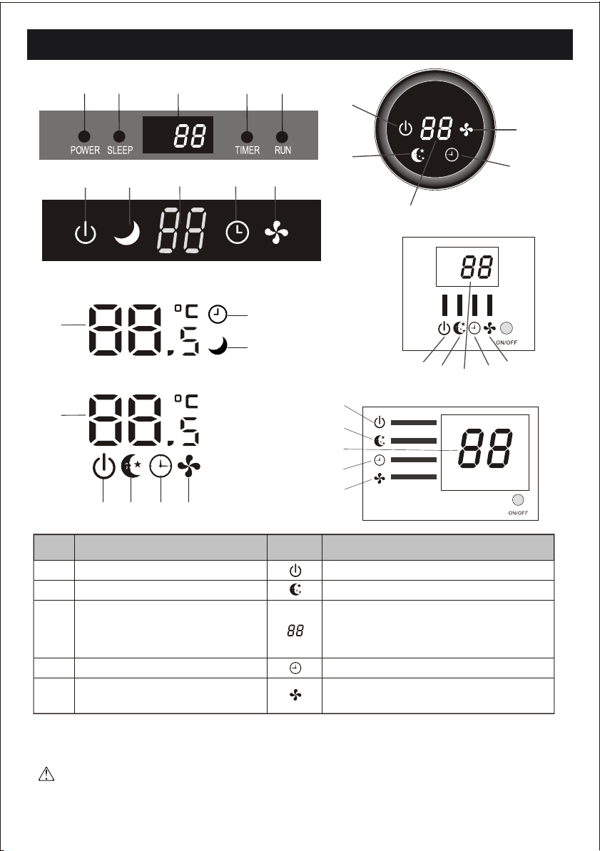
Replacement of Batteries
Remove the battery cover plate from the rear of the remote controller,
by sliding it in the direction of the arrow.
Install the batteries according the direction (+and -)shown on the Remote
Controller.
Reinstall the battery cover by sliding it into place.
Use 2 LRO 3 AAA (1.5V) batteries . Do not use rechar geable
batteries . Replace the old batteries with new ones of the same
type when the display is no longer legible.
Do not dispose batteries as unsorted municipal waste. Collection
of such waste separately for special treatment is necessary.
NOTE:if you adjust the remote controller in cooling mode,
it will not be possible to activate the heating function in units with
heating pump . you need to take out the batteries and repeat the
procedure described above.
1. Direct the remote controller toward the Air conditioner.
2. Check that there are no objects between the remote control
and the Signal receptor in the indoor unit.
3. Never leave the remote controller exposed to the rays of the sun.
4. Keep the remote controller at a distance of at least 1m from the
television or other electrical appliances.
Recommendations for locating and using the remote controller holder (if present)
The remote controller be kept in a wall-mounted holder
Refer to picture 2:
When you insert the batteries for the rst time in the remote
controller or if you change them, you need to program the remote
controller of only cooling or cooling and heating.
When you insert the batteries, the symbols ( ) and
( ) start fashing. If you push whatever button when
the symbol ( ) is displayed, the remote controller is
adjusted in only cooling mode . If you push whatever button when
the symbol ( ) is displayed , the remote controller is
adjusted in Cooling and heating mode.
COOL
HEAT
COOL
HEAT
Refer to picture 1:
i. When you open the battery cover, you can see a DIP switch on
the cover back.l
Ii. NOTE:After adjusting the function, you need to take
out the batteries and repeat the procedure described above.
DIP switch on position
Function
The remotecontroller is adjustedin degree celsius
The remotecontroller is adjustedin only cooling mode
The remotecontroller is adjustedin cooling and heating mode
The remotecontroller is adjustedin degree fahrenheit.
Cool
Heat
C
F

OPERATING INSTRUCTIONS
Filter
Heat
Fan
Exchanger
“SWING ”CONTROL OF THE AIR FLOW
11
aps
ap
movement Deectors
ON/OFF
MODE TIME R
FAN S PE ED SUPE R E CO
SWING SLEE P HEALTHY
ANTI-MIL DEW
MO DE
FAN S L E E P
E C O T IME R
S WIN G
T UR B OH E AL TH Y
DI S P L AY
S WIN G
AIR
SWING
OFF ON
C
AUTOQUIET
POWERFUL
hr
DELAY
TIMER
HEALTHY
AIR
SWING
FAN
SPE ED
DRY
FAN
HEAT
COOL
FEEL
C
h
ON
TIMER
HEALTHY
The direction of the air outlet is motorized up and down
by aps, and manually moved right and left by the vertical
deectors, for some models, the vertical deectors could be
controlled by motor as well.
The air sucked by the fan enters from the grill and
passes through the lter, then it is cooled/dehumidied
or heated through the heat exchanger.
The air outlet ow is uniformly dist-
ributed in the room.
It is possible to position the direction
of the air in the optimal.
In cooling mode , orient the aps in horizontal
direction;
In heating mode, orient the aps downward as
the warm air tends to rise.
The deectors are positioned manually and placed un-
der the aps .They allow to direct the air ow rightw-
ard or leftward.
Never position Flaps manually, the delicate mech-
anism might seriously damaged!
Never poke ngers, sticks or other objects in the air
inlet or outlet vents. Such accidental contact with live
pants might cause unforeseeable damage or hurt.
This adjustment must be done while the appliance
is switched o.
SWING
The key activates the motorized deectors ,
the air ow is directed alternatively from left to right.
(Optional function, depends on the models)
S WING
The key or activates the FLAP ,
the air ow is directed alternatively from
up to down .In order to guarantee an even
diusion of the air in the room.
S WIN G
SWING
OPERATING INSTRUCTIONS
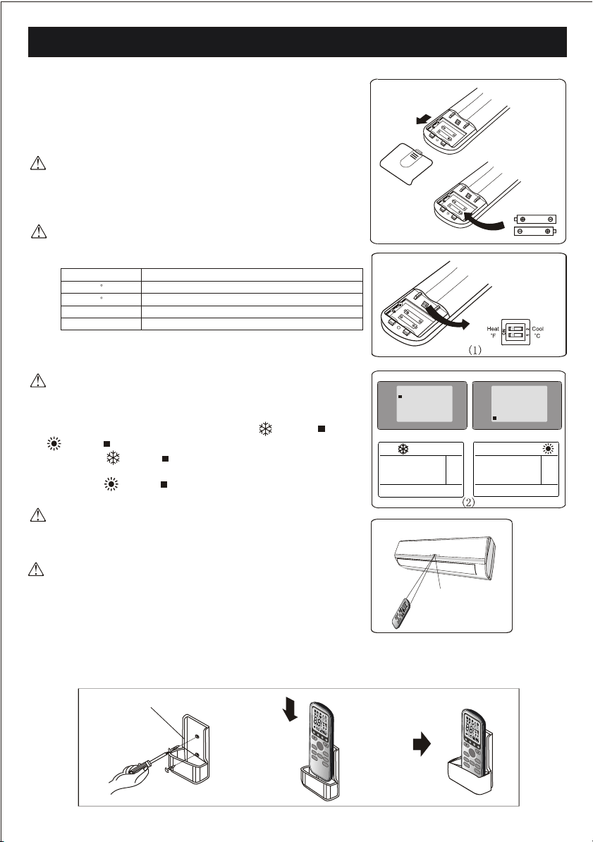
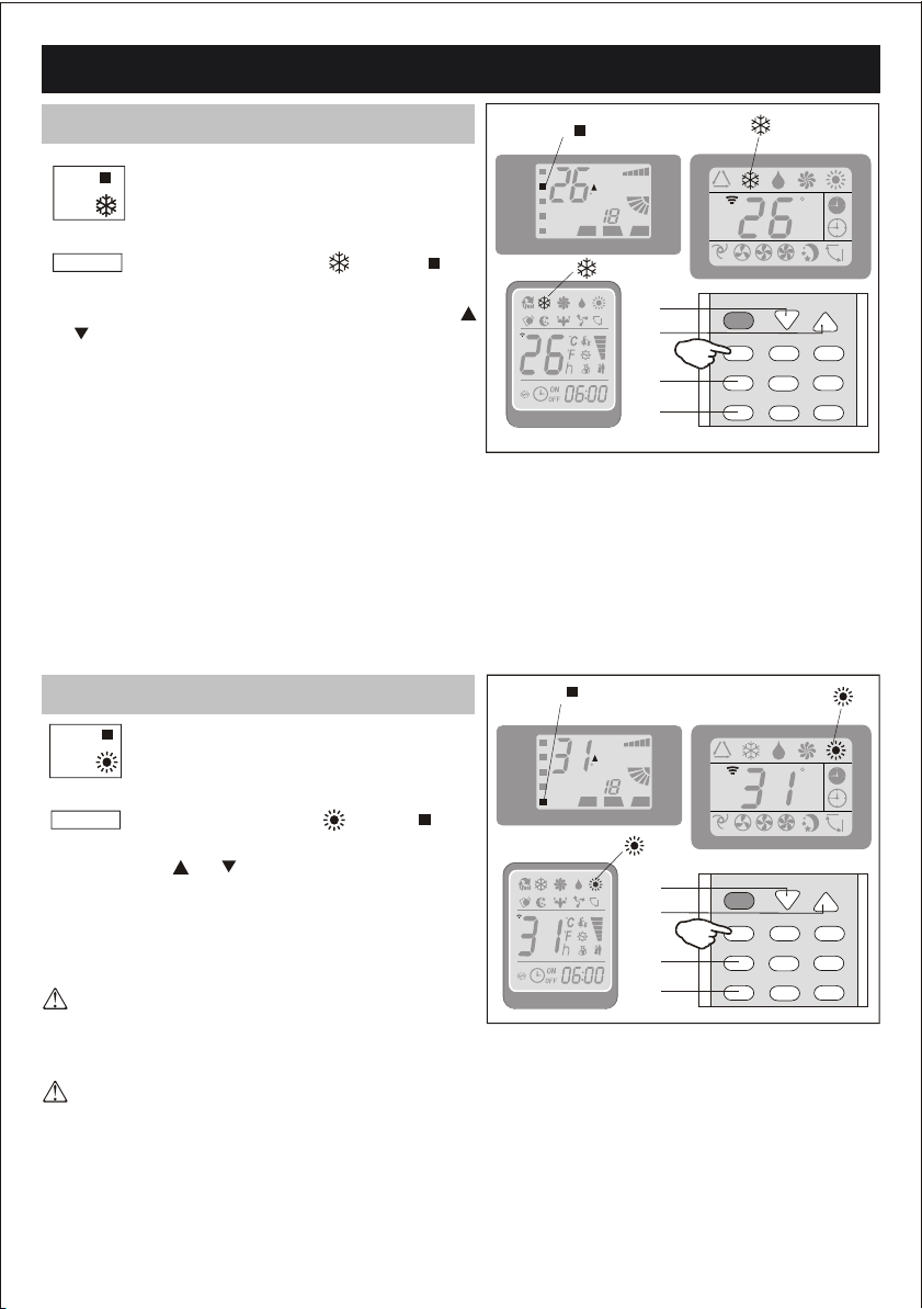
COOLING MODE
The cooling function allows the air condit-
ioner to cool the room and at the same time
reduces Air humidity.
COOL
To activate the cooling function ( COOL ) , press the
MODE button until the symbol ( COOL )
appears on the display.
12
HEATING MODE
OFF ON
C
AUTOQUIET
POWERFUL
hr
DELAY
TIMER
HEALTHY
AIR
SWING
FAN
SPE ED
ON/OFF
MODE TIME R
FAN S PE ED SUPE R E CO
SWING SLEE P HEALTHY
DRY
FAN
HEAT
COOL
FEEL
ANTI-MILDEW
C
h
ON
COOL
1
2
3
OFF
C
AUTOQUIET
POWERFUL
TIMER
HEALTHY
DRY
FAN
HEAT
COOL
FEEL
ON
HEAT
ON
hr
DELAY
AIR
SWING
FAN
SPE ED
C
h
1
ON/OFF
MODE TIME R
FAN S PE ED SUPE R E CO
SWING SLEE P HEALTHY
ANTI-MILDEW
1
2
3
1
TIMER
HEALTHY
TIMER
HEALTHY
The cooling function is activated by setting the button
or at a temperature lower than that of the room.
To optimize the function of theAir conditioner, adjust
the temperature (1) , the speed (2) and the direction
of the air ow (3) by pressing the button indicated.
HEAT
The heating function allows the air conditi-
oner to heat the room.
To activate the heating function ( HEAT ) , press the
MODE button until the symbol ( HEAT )
appears on the display.
With the button or set a temperature higher than
that of the room..
To optimize the function of theAir conditioner adjust
the temperature ( 1 ), the speed ( 2 ) and the direction
of the air ow ( 3 ) by pressing the button indicated
In HEATING operation, the appliance can automatically
activate a defrost cycle, which is essential to clean the
frost on the condenser so as to recover its heat exchange
function.This procedure usually lasts for 2-10 minutes
during defrosting,indoor unit fan stop operation.
After defrosting ,it resumes to HEATING mode
automatically.
If the appliance is tted with a electrical heater,
which delays appliance to startup in a few seconds
to ensure an immediate output of hot air (Optional ,
depends on the model).
OPERATING INSTRUCTIONS
POWER SLEEP TIMER RUN
Indoor display
13
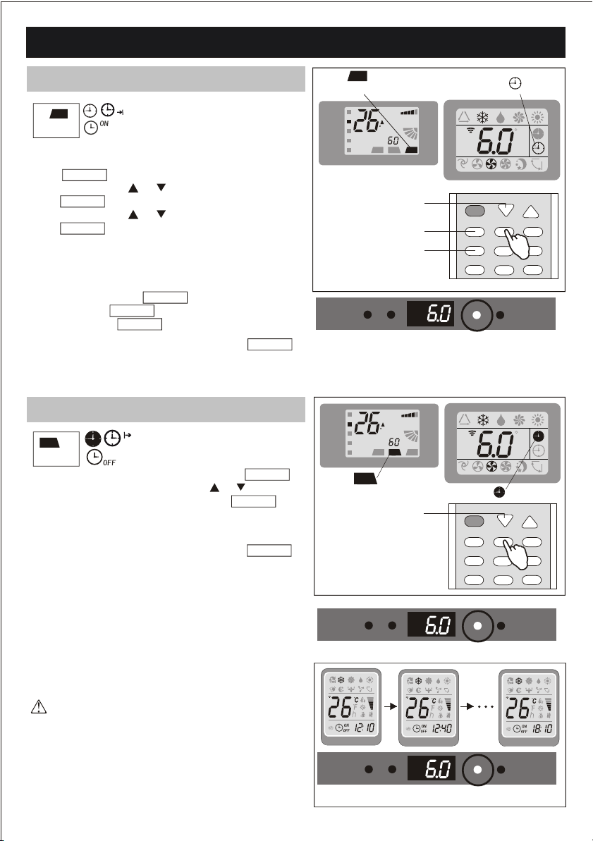
TIMER MODE----TIMER OFF
TIMER MODE----TIMER ON
POWER SLEEP TIMER RUN
Indoor display
TIMER
ON
OFF ON
C
AUTOQUIET
POWERFUL
hr
DELAY
TIMER
HEALTHY
AIR
SWING
FAN
SPE ED
ON/OFF
MODE TIME R
FAN S PE ED SUPE R E CO
SWING SLEE P HEALTHY
DRY
FAN
HEAT
COOL
FEEL
ANTI-MILDEW
C
h
ON
1
2
3
.
TIMER
HEALTHY
TIMER
HEALTHY
Note: The TIMER function can be set at
half-hour intervals.
TIMER
HEALTHY
POWER SLEEP TIMER RUN
Indoor display
TIMER
OFF ON
C
AUTOQUIET
POWER FUL
hr
DELAY
TIMER
HEALTHY
AIR
SWING
FAN
SPE ED
DRY
FAN
HEAT
COOL
FEEL
C
h
ON
OFF
ON/OFF
MODE TIME R
FAN S PE ED SUPE R ECO
SWING SLEE P HEALTHY
ANTI-MIL DEW
1
.
TIMER
ON To set the time of the air conditioner
To program the automatical switching-on time, the
appliance should be power o.
Press TIMER at the st time , set the temperature with
pressing the button or ;
Press TIMER at the second time , set the rest time with
pressing the button or ;
Press TIMER at the third time, conrm the setting, then
the rest time to next automatical switching-on could be
read on the display.
NOTE !
Before proceeding with the time: program the working
mode with the button MODE (2) and the fan speed
with the button FAN (3) . Switch the conditioner
o (with the key ON/OFF ).
TIMER
To set the automatic switching-o
of the air conditioner
The timed stop is programmed by pressing TIMER ,
Set the rest time by pressing thebutton or ,until the rest
time displayed is to your demand then press
TIMER again.
OFF
Note:To cancel the setted function ,press the TIMER
button again.
Note:To cancel the setted function, press the TIMER
button again.
Note:In case of power o,it is necessary to set TIMER
ON again
Note:In case of power o,it is necessary to set TIMER
OFF again

OPERATING INSTRUCTIONS
14
FAN
The conditioner works in only
ventilation.
To set the FAN mode , Press MODE untill
( FAN ) appears in the display .
Whith pressing FAN button the speed changes
in the following sequence: LOW/ MEDIUM/HIGH
/AUTO in FAN mode.
The remote control also stores the speed that was set
in the previous mode of operation.
In FEEL mode (automatic) the air conditioner auto-
matically chooses the fan speed and the mode of
operation (COOLING or HEATING).
This function reduces the humid-
ity of the air to make the room
more comfortable.
To set the DR Y mode , Press MODE untill
( DRY ) appears in the display . An automatic
function of alternating cooling cycles and air fan
is activated.
DRY
FAN MODE
DRY MODE
OFF ON
C
AUTOQUIET
POWERFUL
hr
DELAY
TIMER
HEALTHY
AIR
SWING
FAN
SPE ED
ON/OFF
MODE TIME R
FAN S PE ED SUPE R E CO
SWING SLEE P HEALTHY
DRY
FAN
HEAT
COOL
FEEL
ANTI-MIL DEW
C
h
ON
3
FAN
TIMER
HEALTHY
DRY
OFF ON
C
AUTOQUIET
POWERFUL
hr
DELAY
TIMER
HEALTHY
AIR
SWING
FAN
SPE ED
ON/OFF
MODE TIMER
FAN S PE ED SUPE R E CO
SWING SLE EP HEALTHY
DRY
FAN
HEAT
COOL
FEEL
ANTI-MILDEW
C
h
ON
TIMER
HEALTHY

OPERATING INSTRUCTIONS
Ambient temp Auto temp.
20 23
23
26
20 ~26
Operation mode
H E AT IN G ( F OR H E AT P UM P T Y PE )
DRY
COOL
18
FA N (F O R C O O L O N L Y T Y P E )
To optimize the function of the air conditioner, adjust
the temperature(only 2 )(1), the speed (2) and the
direction of the air ow (3) by pressing the buttons
indicated
To activate the SLEEP mode of operation, press the
SLEEP button on the remote controller until the sym-
bol (AUTOQUIET ) appears on the display.
A U T O Q U I E T
The function SLEEP automatically adjusts the
temperature to make the room more comfortable
during the night . In cooling or dry mode , the set
temperature will automatically raise by1 every
60 minutes, to achieve a total rise of 2 during the
rst 2 hours of operation.
In heating mode the set temperature is gradually
decreased by 2 during the rst 2 hours of operation.
After 10 hours running in sleep mode the air conditio-
ner is swicthed o automatically.
15
FEEL MODE
POWER SLEEP TIMER RUN
Indoor display
FE EL
OFF ON
C
AUTOQUIET
POWERFUL
hr
DELAY
TIMER
HEALTHY
AIR
SWING
FAN
SPE ED
DRY
FAN
HEAT
COOL
FEEL
C
h
ON
ON/OFF
MODE TIMER
FAN S PE ED SUPE R E CO
SWING SLE EP HEALTHY
ANTI-MILDEW
1
2
3
OFF ON
C
AUTOQUIET
POWERFUL
hr
DELAY
TIMER
HEALTHY
AIR
SWING
FAN
SPE ED
DRY
FAN
HEAT
COOL
FEEL
C
h
ON
ON/OFF
MODE TIMER
FAN S PE ED SUPE R E CO
SWING SLE EP HEALTHY
ANTI-MILDEW
AUTOQUIE T
SLEEP MODE
1
.
.
TIMER
HEALTHY
TIMER
HEALTHY
FEEL Automatic mode.
To activate the FEEL (automatic) mode of operation,
press the MODE button on the remote controller until
the symbol ( FEEL ) appears on the display.
In FEEL mode the fan speed and the temperature
are set automatically according to the room temperature
(tested by the temperature sensor which is incorporated
in the indoor unit).

PROTECTION
16
The air conditioner is programmed for comfortable and suitable living conditions, if it is used in abnormal
conditioner as below, certain safety protection features might come into eect.
Outdoor temperature is over 24
2
Room temperature is over 27
Outdoor temperature is below -7
1
3
Heating
Cooling
Dry
Outdoor temperature is over 43
Room temperature is below 21
Room temperature is below 18 C
For T1 Climate condition models:
For Tr opical (T3) Climate condition models:
The unit does not operate immediately if it is turned on after being turned o or after changing the
mode during operation. this is a normal self-protection action, you need wait for about 3 minutes.
No.
MODE
2
1
3
Heating
Cooling
Dry
No.
MODE
Outdoor temperature is over 24
Room temperature is over 27
Outdoor temperature is below -7
Outdoor temperature is over 52
Room temperature is below 21
Room temperature is below 18 C
Ambient temperature
Ambient temperature
The capacity and eciency are according to the test conducted at full-load operation*.
*The highest speed of indoor fan motor and the maximum open angle of the aps and deectors
are requested.

INSTALLA TION MANUAL---Selecting the Installation Place
condensed water drain pipe
150
150
150
Sleeve
insulating covering
electrical cable
Mounting plate
Do not install the outdoor unit near sources of heat,
steam or ammable gas.
Do not install the unit in too windy or dusty places.
Do not install the unit where people often pass.Select
a place where the air discharge and operating sound
will not disturb the neighbours.
Avoid installing the unit where it will be exposed
to direct sunlight ( other wise use a protection , if
necessary, that should not interfere with the air ow).
Reserve the spaces as shown in the picture for the air to
circulate freely.
Install the outdoor unit in a safe and solid place.
If the outdoor unit is subject to vibration, place rubber
gaskets onto the feet of the unit..
water drain pipe
300
500
2000
300
minimum space to be reserved (mm) showing
in the picture
500
Outdoor unit
Indoor unit
be less than 5m
Height should
Outdoor unit
Indoor unit
be less than 5m
Height should
I nstallation Diagr am
17
INDOOR UNIT
OUTDOOR UNIT
The purchaser must ensure that the person and/or company who is to install, maintain or repair this air
conditioner has qualications and experience in refrigerant products.
Install the indoor unit on a strong wall that is not subject
to vibrations.
The in let and outlet ports should not be obstructed:the
air should be able to blow all over the room.
Do not install the unit near a source of heat , steam,or
ammable gas.
Install the unit near an electric socket or private circuit.
Do not install the unit where it will be exposed to
direct sunlight.
Select a site where the condensed water can be easily drained
out, and where it is easily connected to outdoor unit.
Check the machine operation regularly and reserve the
necessary spaces as shown in the picture.
Select a place where the lter can be easily taken out.
Should be less
than 15m
Should be less
than 15m

INSTALLA TION MANUAL---Installation of the Indoor unit
50
5mm
Note : Keep the drain pipe down towards the direction
of the wall hole, otherwise leakage may occur.
Before starting installation, decide on the position of the
indoor and outdoor units, taking into account the minim-
um space reserved around the units
To install, proceed as follows:
The hole must slope downwards towards the exterior
Note : The shape of the mounting plate may be dierent
from the one above, but installation method is similar .
Indoors Outdoors
Front panel
Terminal block cover
wiring diagram
18
Installation of the mounting plate
Drilling a hole in the wall for the piping
Electrical connections---Indoor unit
Do not installyour air conditionerin a
wet room suchas a bathroomor laundry etc
The installation siteshould be 250cmor more
above the oor.
1 Always mount the rear panel horizontally and vertically
2. Drill 32 mm deep holes in the wall to x the
plate;
3. Insert the plastic anchors into the hole;
4 .Fix the rear panel on the wall with provided tapping screws
5.Be sure that the rear panel has been xed rmly enough
to withstand the weight
1. Make the piping hole ( 55) in the wall at a slight
downward slant to the outdoor side.
2. Insert the piping-hole sleeve into the hole to prevent the
connection piping and wiring from being damaged when
passing through the hole.
1. Open the front panel.
2. Take o the cover as indicated in the piciure ( by
removing a screw or breaking the hooks).
3. For the electrical connections, see the circuit diagram
on the right part of the unit under the front panel.
4. Connect the cable wires to the screw terminals by
following the numbering ,Use wire size suitable to
the electric power input (see name plate on the unit)
and according to all current national safety code
requirements.
The cable connecting the outdoor and indoor units
must be suitable for outdoor use.
The plug must be accessible also after the appliance
has been installed so that it can be pulled out if nece-
ssary.
An ecient earth connection must be ensured.
If the power cable is damaged, it must be replaced by
an authorised Service Centre.
Note:Optional the wires can been connected to the main
PCB of indoor unit by manufacturer according to the
model without terminal block.
This manual suits for next models
8
Table of contents
Other Everwell Air Conditioner manuals


Popular Air Conditioner manuals by other brands


Daikin
Daikin FTXN25L Service manual

Gree
Gree Ultra Heat GMV-VQ72W/A-F owner's manual

Berner
Berner DTU1018 instructions

Mitsubishi Electric
Mitsubishi Electric Mr.Slim PLA-RP-BA Series Operation manual

Klarstein
Klarstein METROBREEZE NEW YORK SMART 12K manual

Mitsubishi Electric
Mitsubishi Electric BRANCH BOX PAC-MKA52BC installation manual