Everything Hand Dryers Vega 4 User manual

User Manual
Vega

TECHNICAL SPECIFICATIONS
IMPORTANT SAFETY INSTRUCTIONS
WARNING – TO REDUCE THE RISK OF FIRE, ELECTRIC SHOCK, OR INJURY TO PERSONS OBSERVE THE FOLLOWING:
•
Use this unit only in the manner intended by the manufacturer. The manufacturer is not responsible for
any damages caused by misuse or defective installation.
The instructions contained within the installation Template must be followed carefully when installing
this unit. Failure to accurately follow the instructions may result in the incorrect operation of this unit,
damage to property and/or personal injury.
Installation work and electrical wiring must be done by qualified person(s) in accordance with all
applicable codes and standards, including fire-rated construction.
When cutting or drilling into wall or ceiling, do not damage electrical wiring and other hidden utilities.
This unit must be powered by a dedicated circuit branch protected by a circuit breaker with the
appropriate rating. Circuit cable must be fit current consumption for this unit.
This unit has been designed for indoor use only, protect from water, sun and extreme temperatures, do
not install it outdoors or close to moisture and heat generators.
This unit can only be revised, maintained, repaired and removed by qualified person(s).
If the unit stops and works strangely, contact your regional dealer or contractor.
This appliance is not intended for use by persons (including children) with reduced physical, sensory or
mental capabilities, or lack of experience and knowledge, unless they have been given supervision or
instruction concerning use of the appliance by a person responsible for their safety.
Children should be supervised to ensure that they do not play with the appliance.
•
•
•
•
•
•
⚠
Operating Voltage
Power
Standby Power
Air Speed (sensing max)
Motor Type
Sensor Type
Sensor Range
Timing Protection
Drying Time
Drip Proof
Isolation
Unit Size
AC 220~240 V, 50 Hz- 60Hz
440 W (Heater off)/ 840 W (Heater on)
≤ 1W
100 m/s
Brushed Motor, 30,000 RPM
Auto Infrared touch free operation
45° 15~25cm
50 seconds auto shut off
10 ~ 12 sec
IPX3
CLASS I
H 321.6mm x W 286.6mm x D 110.2mm
UNPACKING
1. Remove all packing material. Recycling is recommended.
2. Carefully remove the hand dryer from the shipping carton, using care not to drop the appliance.
3.
Inspect carefully for any damage that may have occurred during transit. Check for any loose, missing or
damaged parts. If the hand dryer is damaged, promptly inform the shipper or dealer where you purchased it.
Standard items with the hand dryer are shown in Fig.1 together with tools need by the installer.
User Manual
1
Service Tool
& Spare Screw
Installation
template
Wall mounting
anchors with screws
Unit User Manual
Filter enablement pack
(optional extra, sold separately)
Spare Filter Media
INSTALLATION
1. Wall bracket removal
2 3
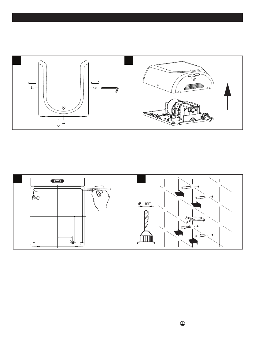
1.1 Place the main unit on a cloth to avoid marking its surface.
1.2
Remove 3 side & bottom security screws , using the service tool (fig.2) .
1.3 Lift the front cover off the main body. (fig.3).
2. Positioning
2.1 Mark the location on the wall with a pencil. Use the Installation Template to mark the locations
for the four fixing points (fig. 4).
2.2 Pre-drill the wall in the marked locations using 5/16” (8mm) drill, insert the plastic anchors and
tap flush to the wall. If the cable entry is to be done from the wall provide a proper cable exit (fig. 5)
8
3. Installing Power cable & Connection terminal block
WARNING: ENSURE POWER NOT CONNECTED
3.1 Pull the cable through the hole in the back panel. Ensure the cable is long enough to the terminal
block (fig. 6).
3.2 Connect cable to terminal block (fig. 6A).
3.3 The cable must sit in the dedicated channel. If the cable comes through Power cable entry from
outside, it is recommended that the cable is routed via the 3 bosses as in fig. 6B.
3.4 Fix 4 wall mounting screws on the back panel (fig. 6).
CAUTION: Connect the ground wire to the terminal block marked “ ”
45
250MM [9 27/32”]
Cable Entrance
Φ 16MM [5/8”]
Drill 4 ~ Φ 6MM [15/64”]
Installation Template
250MM [9 27/32”]
140MM [5 33/64”] 140MM [5 33/64”]
130MM [5 1/8”]
78MM [3 5/64”]

7A
4.If applicable insert the Filter enablement pack & replacing the filter media
6
Power Cable
Entry
NL
Back View
6B
6A
Power Cable Exit
The service life of a HEPA filter depends on the environment in which the dryer is installed and
frequency of use. High traffic washrooms or high usage will require more frequent replacement
of the HEPA filter. In environments with excessive, dust and debris or in washrooms with high
traffic, inspection of the HEPA filter is recommended on a monthly basis. When visual inspection
of the HEPA filter shows excessive buildup of lint, dust and debris, the filter should be replaced.
4.1. First installation time, insert the enablement pack, complete with filter media, into the filter
bracket, and push until it clicks into the right position in the main unit.
4.2. To replace the filter, just pull up the filter media from the enablement pack (fig 7.B) and
replace with new filter media.
Filter
media
Filter
Case
7B
Filter enablement pack
Filter Bracket
Notice- If the dryer has been fitted with a filter, it will need to be replaced after 40,000
operations but will continue working,but without the benefits of the HEPA filter.
At approximately 40,000 operations the red laser light will be flashing on the bottom and the flashing
until a replacement filter is fitted.
⚠
Note: After the filter is installed and on power up should the laser light and blue point light at the
bottom are on for 2 seconds. If laser not light on this means the filter is not fitted correctly and needs
to be refitted.
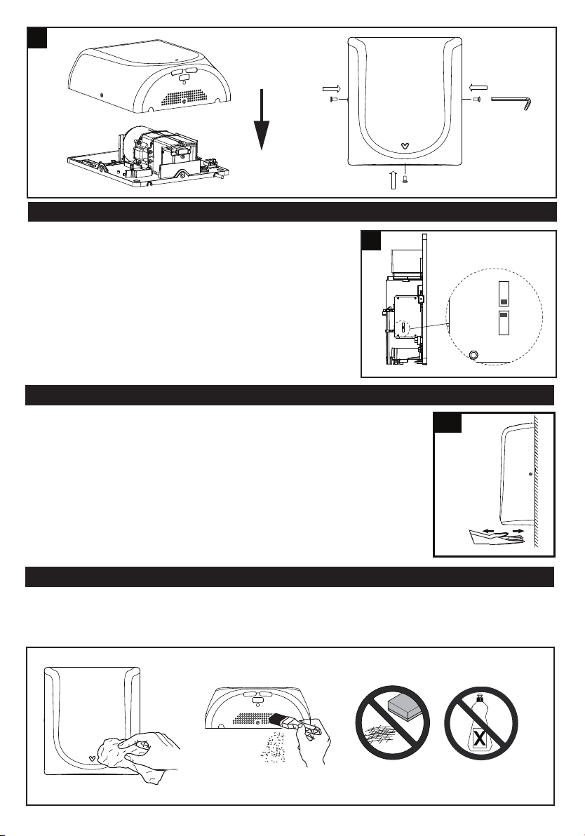
5. Fix the Front cover to unit and insert and tighten the security screw seated on the side&bottom surface (fig 7).
6. Turn power on and test the unit for correct operation.
8
HEATER SWITCH & LOW SPEED MODE SWITCH & FILTER REPLACING
WARNING: ENSURE POWER NOT CONNECTED
1. Remove the one security screw seated on the bottom surface
from the unit, using the service tool (fig. 2).
2. Lift the front cover off the main body. (fig.3).
3. To turn off or turn on heater, use the left switch shown in fig. 8.
4. To change Low speed mode, use the right switch shown in fig. 8.
5. Pull the filter media up and out of the enablement pack, and
insert the new filter media.
6. Reposition the front cover on the unit(fig.8)
7.
Test the unit for correct operation.
9
ON OFF ON OFF
Heat
Lspeed
ON OFF ON OFF
HeatL speed
Use
1. No touch operation.
2. Shake excess water from hands.
3. Place hands under the outlet to start operation (fig. 8).
4. Slowly move hands back and forth under the outlet at the bottom of the dryer.
5. A blue LED light situated at the bottom of the dryer starts with the
dryer operation. This assists the user in keeping the hands in the
dryer’s sensing range.
6. The dryer stops when hands are removed.
7. Hand dryer also auto shuts off after 50 seconds of uninterrupted use.
Maintenance and cleaning
Lift the Unit off the wall mounting bracket before maintenance or repair.
Regularly clean the outer casing use a soft, damp cloth to gently wipe away any dirt.
CAUTION: Never use abrasives or chemicals to clean the cover. Do not soak.
⚠
10
This manual suits for next models
1
Table of contents


