Evident DP75 User manual

Optical Microscope Accessory
A M 5 5 5 4
Instructions
DP75
Microscope digital camera
Note
This instruction manual is for DP75.
To ensure safety, and obtain optimum performance of this product, we
recommend that you study this manual thoroughly before operating this
product, and always keep this manual at hand when this product is in use.
Retain this instruction manual in an easily accessible place near the work
desk for future reference.
For details of products included in the configuration of this system, see page
12.

This product is applied with the requirements of standard IEC/EN61326-1 concerning electromagnetic
compatibility.
- ImmunityApplied to industrial environment requirements.
NOTE:This product has been tested and found to comply with the limits for a Class A digital device, pursuant
to Part 15 of the FCC Rules. These limits are designed to provide reasonable protection against
harmful interference when the product is operated in a commercial environment. This product
generates, uses, and can radiate radio frequency energy and, if not installed and used in accordance
with the instruction manual, may cause harmful interference to radio communications. Operation of
this product in a residential area is likely to cause harmful interference in which case the user will be
required to correct the interference at his own expense.
FCC WARNING: Changes or modifications not expressly approved by the party responsible for compliance could
void the user’s authority to operate the product.
FCC Supplier's Declaration of Conformity
Hereby declares that the product
Product name: Optical Microscope Accessory
Model Number: DP75
Conforms to the following specifications:
FCC Part 15, Subpart B, Section 15.107 and Section 15.109
Supplementary Information:
This device complies with part 15 of the FCC Rules. Operation is subject to the
following two conditions: (1) This device may not cause harmful interference,
and (2) this device must accept any interference received, including
interference that may cause undesired operation.
Responsible Party Name: EVIDENT SCIENTIFIC, INC.
Address:48 Woerd Ave Waltham, MA 02453, U.S.A.
Phone Number:781-419-3900
In accordance with European Directive on Waste Electrical and Electronic Equipment, this symbol
indicates that the product must not be disposed of as unsorted municipal waste, but should be
collected separately. Refer to your local our distributor in EU for return and/or collection systems
available in your country.
For Korea only

Contents
i
1. Introduction 1
2. Safety Precautions 4
2.1 General 4
2.2 Installation 4
2.3 Electric shock prevention 4
2.4 Electrical safety 5
2.5 Injury prevention 5
2.6 Preventing burn 5
2.7 Safety-related labels on the product 6
2.8 Cautions and labels 6
2.9 Handling Instructions 6
2.10 Cyber security 6
3. Restrictions 7
3.1 Specifications subject to restrictions depending on the combination 7
3.1.1 Restriction condition 7
3.2 Specifications subject to restrictions depending on usage conditions 8
3.2.1 Cameras in general 8
3.2.2 Camera images 8
3.2.3 Image data 9
3.2.4 Position navigator 9
3.2.4.1 Prerequisite 9
3.2.4.2 Performance constraints 9
3.2.5 PC combination 11
4. System chart 12
5. Nomenclatures 13
6. Assembly 14
6.1 Attaching the IR cut filter insertion/removal knob 14
6.2 Mounting the camera head 15
6.3 Connecting the interface cables 17
6.4 Connecting external devices 17
6.5 Connecting AC adapter 18
7. Installing software 19
7.1 Software cellSens/PRECiV 19
7.2 Before installing software 19
7.3 The TWAIN driver DP2-TWAIN 19
7.4 Selecting Device 19

8. Summary of steps to acquire the images 21
9. IR cut filter insertion/removal function 23
10. External triggering function 24
11. Maintenance 25
11.1 Cleaning each part 25
11.2 Cleaning IR cut filter 26
12. Troubleshooting 27
13. Specifications 32
13.1 Basic specification table 32
13.2 Table of setting items by software 35
13.3 Operating environment 36
14. Proper selection of the power supply cord 37
ii

DP75
The Microscope Digital Camera DP75 is a product to acquire and process digital images, which is attached to our
microscopes using a C mount camera adaptor made by our company.
The product will not work if a C mount adaptor made by other manufacturer or the product is attached to a
microscope made by other company.
Cautions and confirmation before use
When you unpack the package, check all the included items referring to the list of accessories. If any components
are missing or damaged, contact an Evident distributor.
Configuration of instruction manuals
Read all the instruction manuals supplied with the units you have purchased.
The following instruction manuals are produced for the units to be used with DP75.
Manual names Main contents
DP75
(This instruction manual)
Request for safety, setup procedures, maintenance, troubleshooting,
specifications, etc.
DP75
Quick Reference Guide for
cellSens
Software specifications
Operating procedures, functions, cautions, useful information, etc.
DP75
Quick Reference Guide for
PRECiV
Software specifications
Operating procedures, functions, cautions, useful information, etc.
1. Introduction
1
1. Introduction

How to read this instruction manual
This instruction manual is structured as follows.
6.⚪⚪⚪⚪⚪⚪⚪⚪
⚪⚪⚪⚪⚪⚪⚪⚪⚪⚪⚪⚪⚪⚪⚪⚪⚪⚪⚪⚪⚪⚪⚪
⚪
6.1⚪⚪⚪⚪⚪⚪⚪⚪
⚪⚪⚪⚪⚪⚪⚪⚪⚪⚪⚪⚪⚪⚪⚪⚪⚪⚪⚪⚪⚪⚪⚪⚪
6.1.1⚪⚪⚪⚪⚪⚪⚪⚪
1. Loosen the clamping screw with a screwdriver.
2. Remove the unit .
⚪⚪⚪:
⚪⚪⚪⚪⚪⚪⚪⚪⚪⚪⚪⚪⚪⚪⚪⚪⚪⚪⚪⚪⚪⚪⚪⚪
First level title
Second level title
Third level title
Operating procedure
Cautions and references
1.,2... refer to operating procedures.
(A),(B)... refer to operating parts.
A caution and reference is indicated.
Cautions and references
This instruction manual is structured as follows.
CAUTION:
Indicates a potentially hazardous situation which, if not avoided, may result in minor or moderate injury. It may
also be used to alert the user to unsafe practices or potential material damage.
NOTE:
Indicates a potential situation which, if not avoided, may result in failure of this instrument.
TIP:
Indicates useful knowledge and information for use.
21. Introduction

DP75
Trademark
Microsoft and Windows are either registered trademarks or trademarks of Microsoft Corporation in the United
States and/or other countries.
Intel and Intel Core are trademarks of Intel Corporation or its subsidiaries in the United States and/or other
countries.
Google Chrome is a trademark of Google Inc.
Other company names or product names used in this manual are either registered trademarks or trademarks of
respective companies.
Using open source software
This product includes open source software that is licensed under terms separately stipulated by a third party
(hereinafter referred to as "license terms").
Check the following URL for the open source software included in this product and its license conditions. The
copyright holders of the open source software included in this product are available at the following URL. In
addition, the open source software included in this product makes no warranty including warranties that it does
not infringe on the rights of third parties and implied warranties regarding merchantability or suitability for a
specific purpose.
https://www.olympus-lifescience.com/support/oss-license/dp75/
Please note that we cannot respond to inquiries regarding the contents of the source code provided at the above
URL.
3
1. Introduction

Please use the product in accordance with this instruction manual. If the product is used in a manner not specified
manufacturer, the protection provided by product may be impaired. And it may also cause the malfunction of this
product.
2.1 General
NOTE:
This product is a precision instrument. Handle it carefully and avoid impact on it.
Disassembling the product could cause unexpected accidents or malfunctions. Never disassemble the
product.
Do not use the product in areas where it may be exposed to direct sunlight, high temperature and/or
humidity, dust or vibrations.
(For information about the conditions of operating environments, please refer to “Specifications” (page 32)).
The power cord included is for this product only. It cannot be combined with other products.
Before disposing of this product, be sure to follow the regulations and rules of your local government.
2.2 Installation
CAUTION:
Place the product on a sturdy, level table
For safety reasons in particular, do not place a mat, etc. under the product.
Avoid making the total height of the product higher than 1 m
To prevent the product from falling, avoid a system configuration that makes the total height of the product
higher than 1 m.
Be careful not to drop the product when installing/removing the product
Dropping the camera head and C-mount camera adapter may damage the product or cause injury.
2.3 Electric shock prevention
WARNING:
Never disassemble this product
This could cause electric shock or product failure.
Do not touch the product with wet hands
In particular, if you touch the main switch of the power unit or the power cord with wet hands, this could cause
electric shock, fire, or product failure.
Do not insert tools or pieces of metal into the air vents of the product
This could cause electric shock or product failure.
Do not bend, pull, or tie up the power cord or cables
Otherwise they could be damaged, causing a fire or an electric shock.
2. Safety Precautions
42. Safety Precautions 2.1 General

DP75
Keep the power cord and cables well away from the lamp house
If the power cord or cables gets in contact with the high temperature part of the lamp house, the cord may melt,
which could result in an electric shock.
2.4 Electrical safety
CAUTION:
Always use the AC adaptor and the power cord provided by our company
If the proper AC adapter and the power cord are not used, the electric safety and the EMC (Electromagnetic
Compatibility) performance of the product intended by our company cannot be guaranteed.
The product must be grounded
Connect the ground terminal of the power cord to the ground terminal of the power outlet.
If the product is not grounded, our intended electrical safety and EMC performance cannot be guaranteed.
Do not use the product in close proximity to sources of strong electromagnetic radiation
Proper operation may be disrupted. The electromagnetic environment should be evaluated prior to operation of
the product.
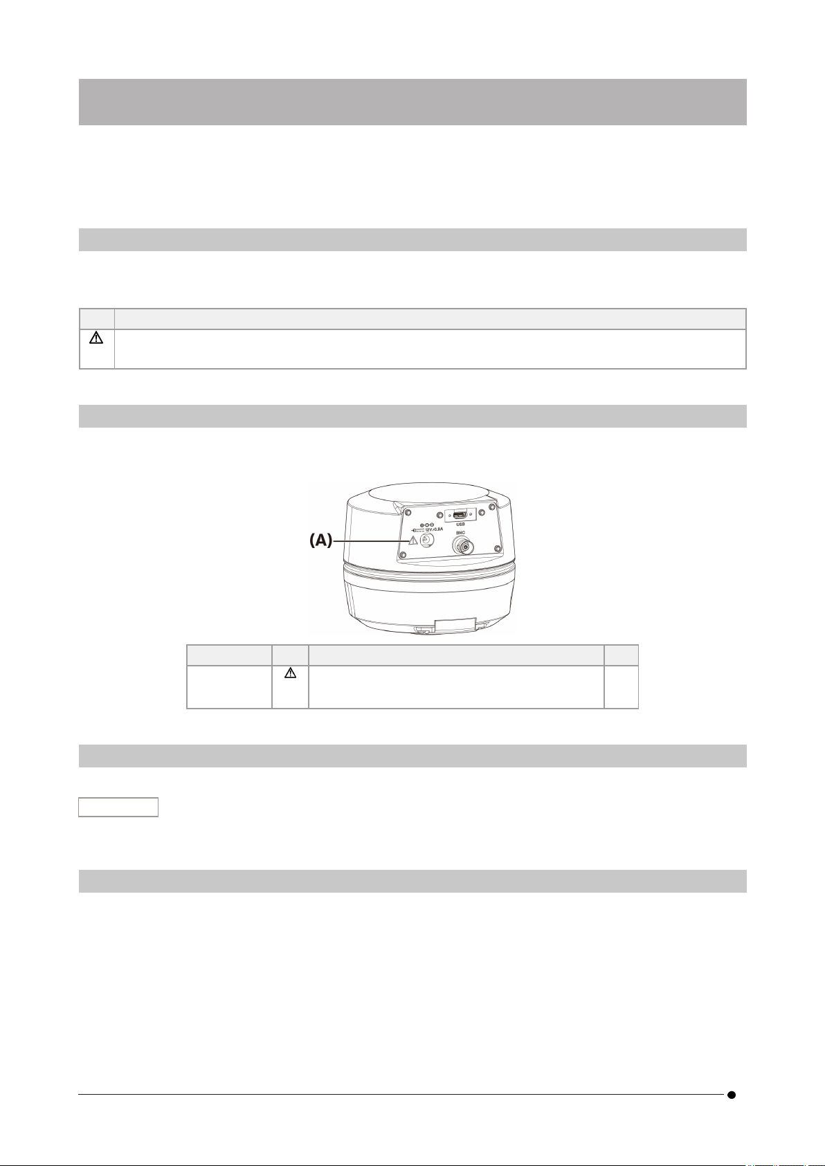
Disconnect the power cord in case of emergency
In case of emergency, disconnect the power cord from the power cord connector on the product or from the
power outlet.
Install the product at the location where you can reach the power cord connector or the power outlet at hand to
disconnect the power cord quickly.
While the power is ON, do not connect or disconnect the power cord, cables, or attach/detach the unit
2.5 Injury prevention
CAUTION:
Do not touch sharp parts of the product
Do not touch the C mount thread because it has sharp edges. Otherwise, you may get injured.
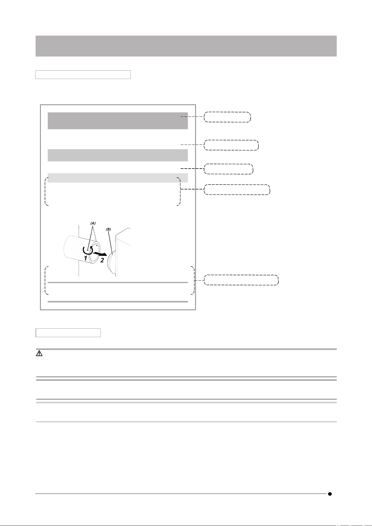
Install the product securely
Screw the C mount camera adapter in to the camera head firmly.
If it is attached loosely, the camera head may drop while in use, causing potential injury.
Do not drop the IR cut filter slider
When removing the IR cut filter slider, take care not to drop it.
The glass of the IR cut filter slider may be broken by dropping it and you may get injured with broken pieces.
Do not put cables on the floor
If you put the cables on the floor, your feet may get caught in the cables, causing the microscope system to tip
over, which may cause the product to break down or the user to get injured.
Run the cable along the wall or place it behind the microscope system so that you can avoid tripping over it.
2.6 Preventing burn
CAUTION:
5
2.4 Electrical safety2. Safety Precautions

Avoid prolonged contact with the product
The camera head heats up when used for a long time. To prevent low-temperature burns, avoid prolonged direct
skin contact with the camera head.
2.7 Safety-related labels on the product
The following symbols are placed on this product.
Study the meaning of the symbols and always use the product in the safest possible manner.
Mark Meaning
Indicates a non-specific general hazard. Follow the cautions given after this symbol or in the instruction
manual.
If labels are soiled or peeled off, please contact our distributor for assistance.
2.8 Cautions and labels
The cautions and caution labels are attached to the portions which require special cautions during use and
operation. Always follow these instructions.
Label position Label Instructions in instruction manual Page
(A) [Safety precautions - Electric safety]
[Safety precautions - Prevention of electric shock]
5
4
If caution labels are soiled or peeled off, contact our distributor for replacement and inquiries.
2.9 Handling Instructions
Intended Use
This product is used for the purpose of acquiring and saving digital images. Do not use digital images acquired,
saved, or analyzed with this product for diagnostic purposes.
2.10 Cyber security
Refer to the instruction manual for the PC or the controller you are using.
62. Safety Precautions 2.7 Safety-related labels on the product

DP75
3.1 Specifications subject to restrictions depending on the combination
3.1.1 Restriction condition
1. Graphic cards
Depending on the type of graphic card used, the highest frame rate for live images may not be ensured.
2. Controller
The controller's installation software in the factory settings is in the scope of warranty. Malfunctions due to
changes in PC environment settings (BIOS changes), OS updates, and installation of third-party software by
the customer are not covered by the warranty. In addition, malfunctions after OS installation with the
recovery disk included in the controller are not covered by the warranty either.
3. Adaptors used in combination with the microscope
This product can be used with C-mount camera adapters marked with "V" or "△" in the table below.
There may be some restrictions depending on the components of the microscope to be combined.
Camera adapter
U-TV0.5XC-3 U-TV0.63XC MVX-TV0.63XC-2 GX-TV0.7XC U-TV1XC U-TV1XC-2
+U-CMAD3-2 MVX-TV1XC
-△- - V V △
V: Can be combined (thee may be some restrictions such as fundamental constraints)
-: Not recommended because the four corners of the image will be darkened due to mismatch with the
specifications of the product.
△: Insufficient peripheral brightness may occur in the field of view depending on the components of the
microscope to be combined. It is recommended to use the shading correction and the partial cropping
function (ROI) of the image together.
4. A list of restrictions
Category Restrictions
1.
Fundamental
constraints
1. When the intermediate lens tube is long (see the example below), there may be
insufficient peripheral light in the field of view depending on the type of lens tube
and objective lens used together.
An example of a long intermediate lens tube:
lTwo or more intermediate lens tubes are combined and used together
lBX3 series: a vertical illuminating light projection tube is used in
combination with the intermediate lens tube
lIX3 series: IX73P2F or IX83P2ZF is used as a microscope body
2. When the AS (aperture stop) is narrowed, spot flare may become noticeable. This
flare becomes less noticeable when the AS (Aperture Stop) is opened.
3. When used in conjunction with a non-NIR compatible microscope, insufficient light
intensity or flare may be noticeable even with the IR cut filter removed.
2. Flare 1. If there is a high-brightness area in the screen that saturates the gradation, flare
may occur in the low-brightness area. It tends to be noticeable when the AS
(aperture stop) is narrowed to close to the minimum, and it will be less noticeable
when the AS (aperture stop) is opened. In addition, it will be less noticeable if
exposure amount is suppressed to the extent that the gradation is not saturated.
3. Restrictions
7
3.1 Specifications subject to restrictions depending on3. Restrictions

2. When observing a sample with weak fluorescence with the IR cut filter removed (or
without a sample), flare may be conspicuous that depends on the characteristics of
the mirror unit if light sources that use a mercury lamp are combined.
3. Restrictions
when
individual
products are
combined
1. Flare may be conspicuous if a filter with high reflectance (45LBD-IF, etc.) is inserted
into the filter holder of the microscope.
It will be less prominent by inserting an ND filter for transillumination or low-
reflection type ND filter (45-ND25, etc.) on the condenser side of the high-
reflectance filter.
3.2 Specifications subject to restrictions depending on usage conditions
3.2.1 Cameras in general
1. Because the pixel shift mechanism is sensitive to impact, avoid any impact to it when attaching it to or
removing it from the microscope. Be sure to use the dedicated packaging box when transporting this
product.
2. It is necessary to perform calibration periodically (approximately once every three months) for late-onset
pixel defects caused by cosmic rays. (operate with cellSens / PRECiV / DP2-TWAIN)
3. Do not use live images, captured images, or analytical images using these images for diagnostic purposes.
4. Pixel shift imaging of 8192 x 6000, 4096 x 3000 pixels (3CMOS mode) by external trigger input is not
available.
3.2.2 Camera images
1. Image disturbance such as a hatching pattern will occur when the specimen is moved during pixel shift
imaging with 8192 x 6000, 4096 x 3000 pixels (3CMOS mode).
2. Image disturbance such as a hatching pattern will occur if there is camera or microscope vibration during
pixel shift imaging with 8192 x 6000, 4096 x 3000 pixels (3CMOS mode).
Factors that cause vibration include operating the keyboard/mouse or equipment with a built-in air cooling
fan on the desk on which the microscope with the camera has been placed.
3. When the live noise reduction function is enabled, afterimages or blackened areas may occur when the
specimen (stage) is moved.
4. When using the live HDR function, afterimages will occur if the stage is moved.
5. With still image HDR, pixel shift imaging of 8192 x 6000, 4096 x 3000 pixels (3CMOS mode) is not available.
6. Auto white balance does not work properly with light sources other than halogen light sources or high
color rendering LED light sources.
7. Color reproduction is different before and after insertion of the IR cut filter.
8. Auto black balance may leave the background stood out depending on the observing conditions.
9. Scenes may not be determined correctly in scene recognition.
Specific examples:
lwhen there is no specimen in the field of view, or the contrast of the specimen is low, or the image
is greatly out of focus, BF is erroneously determined as DIC/PH
lwhen switching the optical path, erroneous determination of fluorescence observation is made
lspecimens for industrial use (examples: substrates, metal etc.)
10. Flashing defective pixels may appear during long-time live imaging.
83. Restrictions 3.2 Specifications subject to restrictions depending on

DP75
3.2.3 Image data
Please bear in mind the following matters about image data.
1. The recorded image data may be lost (corrupted) in the following cases. Please note that we are not liable
for any loss (damage) of recorded data.
lWhen the product is repaired by the customer or a third party,
lWhen the PC is shut down or the power cord is unplugged while the PC is recording or erasing
(initializing) data,
lWhen the cable is disconnected while still images or movies are being imported,
lWhen data is stored beyond the data retention period (approx. 1 to several years) of the electronic
recording media such as a USB memory stick,
lWhen product malfunction occurs
2. Please note that we cannot restore images and compensate for damage in the following cases even
though the camera functions normally.
lWhen images are abnormal,
lWhen file properties, e.g. file name, file date/time, etc. are abnormal,
lWhen images are lost
3. In general, because storage media such as a USB memory stick, built-in/external storage, CD-R, DVD-R, etc.
have a data retention life, saved files may be lost after several years.
4. The image data may be lost (corrupted) unexpectedly. Therefore, please frequently back up data you have
obtained.
5. Please make sure that there is no problem in capturing the image of the specimen before importing the
image. Please note that we will not be liable for any problems caused by the captured images.
3.2.4 Position navigator
3.2.4.1 Prerequisite
The position navigator cannot be used with cellSens Entry, PRECiV Capture, and DP2-TWAIN.
3.2.4.2 Performance constraints
1. The position navigator does not guarantee operation for all specimens, observation conditions, and
operation methods.
2. The position navigator does not support:
lrotation of observed images due to rotation of stage, specimen, etc.
la condition in which no specimen exists within the observation field of view
lchanging magnification of lenses other than the object lens (for example, intermediate variable
magnification apparatus)
3. Mapping accuracy in the position navigator function may be reduced for dark or low-contrast specimens.
4. In the following cases, magnification estimation may not be successful when objective lenses are switched,
using the position navigator function.
lFluorescence observation in modes other than Low Light mode
lMagnification ratio of objective lenses before and after switching is 5x or more
lObservation of specimens with uniform object structures
9
3.2 Specifications subject to restrictions depending on3. Restrictions

lPart of the imaging range is off the created map
lStage movement just before or after switching objectives
In addition, switching optical elements such as mirror unit cassettes and condensers, and switching optical
paths in components such as a trinocular tube etc., may be mistakenly detected as switching objective
lenses.
10 3. Restrictions 3.2 Specifications subject to restrictions depending on

DP75
3.2.5 PC combination
1. Requirement of PC to be combined
item Specifications
CPU Intel Core i5, Intel Core i7, Intel Xeon, or equivalent
RAM 8GB or more (16GB or more recommended)
Internal storage Free space: 5GB or more
Graphics 1280x1024 or higher monitor resolution, video card capable of 32-bit color output
*Onboard graphics also available
I/F USB 3.1 gen2(TypeA) gen1 (5Gbps) port also available
OS Windows10 Pro (64bit)
Windows11 Pro (64bit)
*Environment required for Live HDR
lNVIDIA CUDA compatible graphic board (compute capability 3.5 or higher)
lGraphic board driver that supports CUDA11.8 or higher
2. Free storage space
PC internal storage has enough free space to allow system installation and operation without causing any
problem.
11
3.2 Specifications subject to restrictions depending on3. Restrictions

IR cut filter
Insertion/remo
val knob
DP75
Camera head
C mount
Camera adapter
AC adapter
Interface cable
(USB)
External trigger
(Shutter unit etc.)
Power cord
Monitor
4. System chart
12 4. System chart

DP75
NOTE:
Use products that are designated by our company or comply with the requirements of IEC60950 CISPR22.24
(international standard for equipment safety) when connecting them to this product. If other products are
connected, complete performance cannot be guaranteed.
Nomenclature of each part
(A) LED status indicator (P.27)
(B) Cap screw (P.14)
(C) IR cut filter insertion/removal knob (P.14) , (P.23)
(C) Interface cable (P.17)
(D) AC adapter jack (P.17)
(E) USB connector (P.17)
(F) BNC cable jack (P.17)
(G) C mount lens cap (P.14)
Nomenclature of each part
(H) Interface cable (P.17)
(I) AC adapter
(J) Software (cellSens / PRECiV)
(K) PC
5. Nomenclatures
13
5. Nomenclatures

6.1 Attaching the IR cut filter insertion/removal knob
The assembly in this chapter is not necessary if you are not observing fluorescence in the NIR (near infrared)
wavelength range. When using it, use a microscope that supports NIR observation.
1. Use your flathead screwdriver (Tip thickness: about 0.7 to 0.9 mm) to remove the cap screw (A) attached to
the camera head by turning it counterclockwise.
NOTE:
lKeep the cap screw in a safe place so that it will not be lost.
2. Attach the IR cut filter insertion/removal knob (B) to the IR cut filter slider bar (C) by turning it clockwise to
the end.
NOTE:
lScrew the IR cut filter insertion/removal knob in firmly so that it does not become loose.
6. Assembly
14 6. Assembly 6.1 Attaching the IR cut filter insertion/removal knob

DP75
6.2 Mounting the camera head
NOTE:
lDo not touch the C mount thread (c) because it has sharp edges.
lWhen attaching or removing the camera head or the C mount camera adapter, be careful not to drop them.
lScrew the C mount camera adapter into the camera head firmly. If it is attached loosely, the camera head may
drop during operation or the sufficient performance may not be obtained when acquiring the image.
As an example, the procedure for using the C-mount camera adapter (U-TV1XC) is explained.
1. Remove the C-mount lens cap (A).
2. Screw the C-mount camera adapter (B) in to the C-mount screw (C) on the bottom of the camera head by
turning it clockwise to the end.
3. Attach the C-mount camera adapter to the microscope's camera port.
Back of C-mount camera adapter
15
6.2 Mounting the camera head6. Assembly

TIP:
lOperate the screw (LOCK) (E) and screw (CENTERING) (D) when adjusting parfocality. Set the C-mount camera
adapter to an appropriate direction so that the screw (CENTERING) is easy to operate.
lBe sure to adjust parfocality between the C-mount camera adapter and the eyepiece. Otherwise, either the
image through the eyepiece or that of the camera may not stay in focus. Please refer to the instruction manual
of the C-mount camera adapter you are using for the parfocal adjustment method.
lIf the orientation of the camera is not correct, the orientation of the image seen through the eyepiece and that
of the camera image will not match. After completing the hardware installation, compare the image seen
through the eyepiece with the live image from the camera and rotate the C-mount camera adapter until the
images match.
lThe figure is a rough viewing range. Before use, check the actual viewing range by using a sample with a scale
function.
lWhen using a third-party C-mount camera adapter, full optical performance may not be obtained.
NOTE:
lDo not use C-mount camera adapters made by other companies that have a thread part dimension (D) of 4.5
mm or more, as they will collide with and damage the components inside the camera head.
Field number
22
0.63 x
(Diagonal length: Equivalent to 27.8 fields)
1 x
(Diagonal length: Equivalent to 17.5 fields)
16 6. Assembly 6.2 Mounting the camera head
Table of contents