Evil Mad Scientist Alpha Clock Five User manual

Alpha Clock Five
Al
p
hanumeric LED Clock & Data Dis
p
la
y
Devices
For version 2.0 kits
– Red,White, and Blue Editions –
Manual v. 2.2
© 2018 Evil Mad Science LLC
An open-source hardware+software project. For support links,
design files, source code, & additional documentation,
please visit: https://wiki.evilmadscientist.com/alpha
evilmadscientist.com

Line
Ref Des
Description
Manf./Vendor
Part number
Qty
1
2
3
4
5
6
7
8
9
10
11
12
13
14
15
16
17
18
19
20
21
22
23
24
25
26
27
28
29
30
31
32
33
34
n/a
Alpha Clock PCB, Rev C.
Evil Mad Scientist
60-0032
1
R5, R9
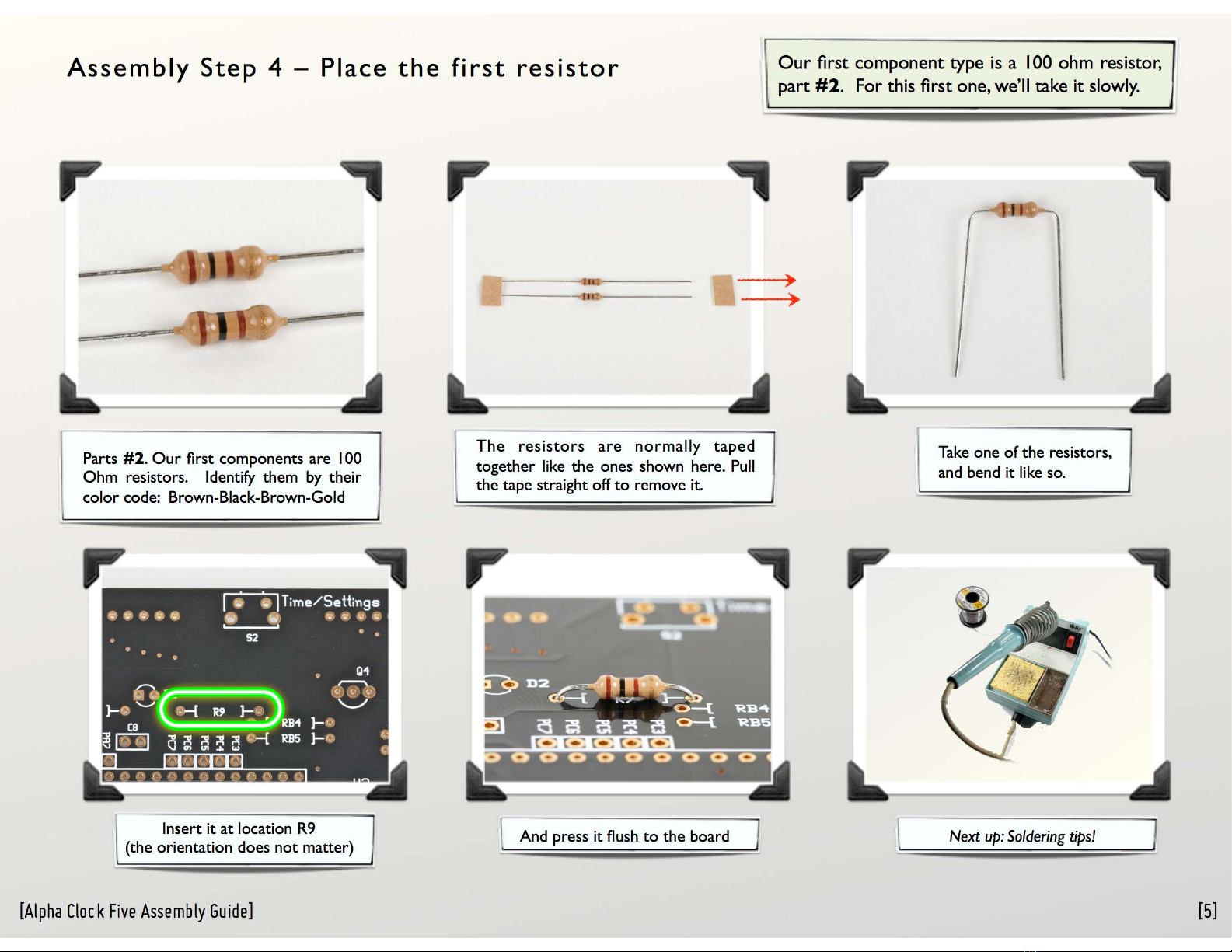
Resistor, 1/4 W Axial, 100 ohm
Digi-Key
100QBK-ND
2
R3, R4
Resistor, 1/6 W Axial, 10K
Digi-Key
10KEBK-ND
2
R1
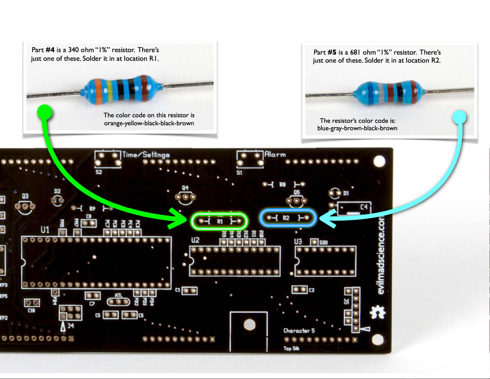
Resistor, 1/4 W Axial, 340 ohm 1%
Digi-Key
340XBK-ND
1
R2
Resistor, 1/4 W Axial, 681 ohm 1%
Digi-Key
681XBK-ND
1
RP1, RP2
Res. pack, 10K, NOTE POLARITY
Digi-Key
4606X-1-103LF-ND
2
RP5, RP6
Res. pack, 1k isolated
Digi-Key
CSC1.0KG-ND
2
U1
Socket, DIP, 0.6” wide, 40 pin
Digi-Key
3M5471-ND
1
U2
Socket, DIP, 0.3” wide, 24 pin
Digi-Key
3M5466-ND
1
U3
Socket, DIP, 0.3” wide, 16 pin
Digi-Key
3M5463-ND
1
U5
Socket, DIP, 0.3” wide, 14 pin
Digi-Key
3M5462-ND
1
J4
Header, 0.1”, 6 pin, DIL (extra long)
Digi-Key
609-3370-ND
1
M1
Header, female, 4 pin
Digi-Key
S7037-ND
2
J1
Power jack, 2.1 mm x 5.5 mm
Digi-Key
CP-002AH-ND
1
C5, C6
Capacitor, ceramic, 18 pF
Digi-Key
BC1004CT-ND
2
C1-3, 7, 8, 10, 12
Capacitor, ceramic, 0.1 uF
Digi-Key
BC1148TR-ND
7
XTL
Crystal: 16 MHz, 20 ppm
Digi-Key
535-9041-ND
1
J2, J5
Header, 0.1”, 6 pin, SIL, RA
Digi-Key
WM6106-ND
2
D2
LED, 3 mm, White Diffused
Betlux
BL-L312-UWW
1
Q1-Q6
PNP transistor, type 2STX2220
Digi-Key
497-7067-ND
6
U4
TL750L05 voltage regulator
Digi-Key
296-8002-5-ND
1
C4,C9, C11
Capacitor, aluminum, 100 uF, 16 V
Digi-Key
493-1040-ND
3
S1-S5
Switch, tactile RA, tall button
Digi-Key
P10880S-ND
5
L1
Buzzer, Magnetic
Digi-Key
102-1155-ND
1
U1
IC, microcontroller, ATmega644A,
preprogrammed with firmware v 2.0
Digi-Key
ATMEGA644A-PU-ND
1
U2
IC, LED Driver, type MBI5026
Macroblock
MBI5026GN
1
U3
IC, LED Driver, type MBI5168
Macroblock
MBI5168GN
1
U5
IC, Buffer, type SN7407N
Digi-Key
296-1436-5-ND
1
n/a
Bracket, right angle, 6-32 threaded
Digi-Key
4334K-ND
2
n/a
6-32 x 3/8" Phillips Screw
McMaster-Carr
91772A146
4
LD1-LD5
Machine Pin Socket, 10 pin SIL
JameCo
102201
10
LD1-LD5
LED, Alphanumeric White 2.3" (each)
Betlux
BL-S230B-13W-12
5
n/a
Power Supply 9 V 1 A (2.1 mm plug)
Various
1
n/a
Chronodot Module
Macetech
1
To put your kit together, you’ll need the build instructions.
Please visit: http://wiki.evilmadscientist.com/alpha
This document lists everything that comes with the kit.
If you find that anything is missing or broken, please let
us know right away and we’ll get you squared away.
>>> sales@evilmadscientist.com <<<
BILL OF MATERIALS:: Alpha Clock Five, White Edition. Kit version 2.0 / Firmware version 2.0
Line
Description
Manf./Vendor
Part number
Qty
35
36
37
38
39
40
Acrylic Case, front (smoke)
Evil Mad Scientist
61-0039
1
Acrylic Case, back (smoke)
Evil Mad Scientist
61-0036
1
Acrylic Case, top (black)
Evil Mad Scientist
61-0037
1
Acrylic Case, bottom (black)
Evil Mad Scientist
61-0038
1
Hex nut, zinc plated, 4-40
McMaster-Carr
90480A005
12
4-40 x 1/2” Phillips screw, black
McMaster-Carr
91249A111
12
Case kit:
[2]
Your kit comes with a bill of materials, the authoritative,
up-to-date list of what’s included with your particular kit. In the instructions, we refer to components by their line
item number on the bill of materials. For example, #1 on
the BOM is the Alpha Clock Five printed circuit board.
Assembly Step 1 – Line numbers and the BOM
This assembly guide covers both the Red, White, and Blue
editions of Alpha Clock Five.These editions have slightly different
circuitry, and thus different instructions in several of the
assembly steps. In those steps, please pay careful attention to
follow the instructions labeled for your color of clock.
(There are also “Basic Edition” Alpha Clock Five kits, which are
normal Alpha Clock Five kits except that they do not include the
Chronodot module or acrylic case.)
Acrylic Case
Chronodot Module
[Alpha Clock Five Assembly Guide]

Four Essential tools: Needed to build the kit:
Suggested, but not required
[Alpha Clock Five Assembly Guide]
And for the adventurous...
1. USB-TTL Cable
FTDI model TTL-232R or equivalent. A “smart”
converter cable with a USB interface chip inside. One end
hooks up to your USB port, the other to the clock. This
allows you to program the Clock through a modified
version of the Arduino development environment
( http://arduino.cc/ ).
Besides programming, the cable can also be used to sync
the time or display data on the clock through a serial
program.
2. Computer, Internet access, USB port....
All of the software and source code that you’ll need to reprogram Alpha
Clock Five is available online for free. You’ll need a reasonably recent
vintage computer (Mac,Windows, or Linux) and internet access.
Additional information is available at the project page:
http://wiki.evilmadscientist.com/alpha
Resistor lead forming tool
Allows fast, neat bending of resistor leads. Not that many parts
like this in the kit, but if you like it extra nice....
[3]
Phillips-head screwdriver, medium size. (#1 is ideal.)
4. Screwdriver
Alpha Clock Five is a soldering kit. You’ll
need certain tools and supplies to build it.
1. Soldering iron
2. Solder
3.Angle Flush Cutters
Thin rosin core solder.
60/40 solder is easy to use;
diameter of .025” or so is typical
for work like this.
Either standard (lead-bearing) or newer
“lead free” solder types will both work
just fine.
For clipping loose wire ends.
e.g., Sears Craftsman
A basic soldering iron meant for electronics, with a
reasonably fine point tip. We recommend one of
this design-- a "pencil shape" soldering iron (not
gun!) with a base that holds the iron and a wet
sponge.
While you don’t need an expensive one, the iron
can make a big difference in the time needed to
build the kit. (Seriously. If you use one that is old
and busted, or an ultra-low-end $10 iron, expect
to spend at least twice as long soldering!)
Our recommendation for a low-cost iron:
WLC100 by Weller, about $40.
Assembly Step 2 – Tool Checklist

The Alpha Clock Five printed circuit board (PCB),
listed as line item #1 on your bill of materials.
Assembly Step 3 – Circuit board and first component locations
Our first assembly step will be to add components in
locations R5 and R9 on the circuit board. Locate these two
locations on your circuit board, as shown highlighted here.
[Alpha Clock Five Assembly Guide] [4]
Sanity check!
This set of instructions is for Alpha Clock Five kits version 2.0,
which are based around revisions C/D of the circuit board.
To make sure that you’re reading the right set of instructions, confirm at
this time that your circuit board says “Rev. C” or “Rev. D” at the location
shown by this here arrow.

Assembly Step 4 – Place the first resistor
Parts #2. Our first components are 100
Ohm resistors. Identify them by their
color code: Brown-Black-Brown-Gold
The resistors are normally taped
together like the ones shown here. Pull
the tape straight off to remove it.
Take one of the resistors,
and bend it like so.
Insert it at location R9
(the orientation does not matter) Next up: Soldering tips!
Our first component type is a 100 ohm resistor,
part #2.For this first one, we’ll take it slowly.
And press it flush to the board
[Alpha Clock Five Assembly Guide] [5]

[6]
(0). Pre-form the leads of components if needed.
(For example, like the resistor in the last step.)
(1). Insert each component into the circuit board, from
the top, at its given location. Push it flush to the board
(Note that some components, like the chips and LEDs,
need to be inserted with a particular orientation.)
(2). If your component has flexible leads, gently bend the leads
out, up to 45°, to hold it in place while you solder.
(3). One at a time, from the back side, solder the leads of
the component to the circuit board.
(4). If the component has long and/or or flexible leads, clip off
the extra length, close to the board. (But not so close that
you’re clipping the board itself.)
• Your tip needs to be shiny (tinned). If not, melt some fresh
solder against it and quickly swipe clean on a wet sponge.
• Place the solder against the joint that you wish to connect.
• Touch the iron to the solder and joint for about one second.
Count it out:“one thousand one.”
• The solder should melt to the joint and leave a shiny
wet-looking joint. If not, let it cool and try again.
Adding components to the circuit board
As the old Heathkit manuals say, “it is interesting to note” that the vast majority of problems
reported with soldering kits turn out to be due to unreliable solder connections.
Before we go further, here’s a quick refresher, with our suggested procedures for adding
components to the circuit board. These procedures apply to most components in the kit.
To be continued...
(3) Solder!
(4) Clip!
(1) Insert! (2) Bend!
45°, max
Assembly Step 5 – Some tips on soldering
[Alpha Clock Five Assembly Guide]

And finally, repeat this procedure, to install the
other #2 resistor at location R5.
Assembly Step 6 – Solder that first resistor
On the back side, Bend out the two leads of the resistor
(Where we perform those steps that we just described!)
Solder both pins to the board.
Inspect the solder joints. Make sure
that they look shiny, wet, and clean,
to ensure a good connection.
Clip the excess leads short.
Bend!
[7][Alpha Clock Five Assembly Guide]

Assembly Step 7 – Install Resistor #3
[Alpha Clock Five Assembly Guide] [8]
#3 is the only smaller size resistor. Up close, the color stripes are
brown-black-orange-gold.
Parts identification:
Next, solder parts #3, two 10 k resistors,
into locations R3 and R4.

Assembly Step 8 – Install Resistors #4 & #5
[Alpha Clock Five Assembly Guide] [9]
Part #5 is a 681 ohm “1%” resistor. There’s
just one of these. Solder it in at location R2.
The resistor’s color code is:
blue-gray-brown-black-brown
The color code on this resistor is
orange-yellow-black-black-brown
Part #4 is a 340 ohm “1%” resistor. There’s
just one of these. Solder it in at location R1.

Assembly Step 9 - Resistor packs.
[Alpha Clock Five Assembly Guide]
For RED Alpha Clock Five only:
If you are building a WHITE or BLUE Alpha Clock Five,
skip ahead to the next page, Step 9B.
JP1 RP4
RP3
Parts #6 are two 560 ohm resistor packs.
Insert them into locations RP3 and RP4,
and solder all six pins of each into place.
(The orientation does not matter.)
You may find it helpful to slightly bend out
one or two of the pins of each, on the
bottom side, to hold them in place while
you solder.
Part #7 is a single “zerohm” jumper; it looks
like a resistor with a single black stripe.
Install it, as you would a resistor, at location JP1.
After installing these three components,
advance to Step 10, skipping Step 9B.
Highlighted here are the component locations
for JP1, RP3, and RP4 on the circuit board:
[10]

Assembly Step 9B - Resistor packs.
[Alpha Clock Five Assembly Guide]
For WHITE or BLUE Alpha Clock Five only:
If you are building a RED Alpha Clock Five,
skip ahead to the next page, Step 10.
For these resistor packs, the orientation does not matter.
Insert them into locations RP5 and RP6, and solder all six
pins of each into place in the same way as for parts #6.
Parts #7 are two 1 k ohm resistor packs:
On each of the #6 resistor packs, locate “Pin 1,” which
is marked by a little circle on the of the resistor pack’s
body.
These two components go into locations RP1 and RP2
on the circuit board. Note however, that you need to
place them with a specific orientation: “Pin 1,” of each
resistor pack needs to be inserted into the “Pin 1” hole
of locations RP1 and RP2.
The “Pin 1” holes are the ones with the square pads,
indicated here with arrows.
After inserting parts #6 with the correct orientation,
solder all six pins of each into place. You may find it
helpful to slightly bend out one or two of the pins of
each, on the bottom side, to hold them in place while
you solder.
Highlighted here are the component
locations for RP1, RP2, RP5, and RP6
on the circuit board:
Parts #6 are two 10 k ohm (yellow) resistor packs:
[11]

There is a corresponding footprint for the
socket, at location U1 on the circuit board.
It has a corresponding notch at one end.
Flip the circuit board over, while keeping
the socket in place.
Insert the socket into the circuit board,
matching the two ends with the notches.
This is #8, the 40-position socket for the
microcontroller. Locate the polarity
marking notch at one end of the socket.
Assembly Step 10 – The 40-pin IC Socket
[12]
[Alpha Clock Five Assembly Guide]
To ensure good positioning, rest the
circuit board flat on top of the socket.
The socket pins will protrude (but only
very slightly) through the circuit board

Then, on the top side, check that the
socket is level and flush to the board.
As before, solder all of the pins
on the back side.
(And, do not insert any of the chips
just yet– we’ll do that later.)
One at a time, install the DIP sockets in
locations U2 and U3 (as well as U5, if building a
Blue or White kit), using the same method used
for the 40-pin socket. Again take care to match
the notches to those on the circuit board
Parts #9 and #10 are 24-pin and 16-pin DIP
Sockets, respectively. Blue/White Alpha Clock
Five kits also include a #11, a 14-pin DIP socket.
Note that each has a notch at one end to mark
the polarity.
Then, solder the rest of the socket pins.
To begin with, solder just two opposite
corner pins of the 40-pin socket.
Assembly Step 11 – Sockets, continued
[13]
[Alpha Clock Five Assembly Guide]
#9
#10
#11,in
blue/white kits

Part #12 is a 6-pin DIL (dual inline) header. It goes in location J4. Flip the board over, so that you can rest it
on the header, to hold it in place while
soldering.
On the top side, make sure that the header sits
flush to the circuit board. If not, flip it back over,
and melt the joint while pressing down on the
circuit board, to snap the header into place.
Assembly Step 12 – Six-pin DIL ISP Header
[14]
[Alpha Clock Five Assembly Guide]
Solder just one pin to begin with. Then, solder the other five pins.

Finally, solder the other
three pins of each header.
On the top side, straighten the headers, and
make sure that they are flush and square to
the board.
Parts #13 are two 4-pin female
headers that go at location M1.
There are actually two rows of holes at M1.
Note that the headers go in the outer positions. Insert the two headers...
In this step, we add the sockets that allow Alpha Clock Five to
be connected to a real-time clock module (e.g., Chronodot)
Assembly Step 13 – RTC Sockets
[15]
[Alpha Clock Five Assembly Guide]
...And flip the board over to rest on them,
holding them in place for soldering.
Solder one pin of each header.

Assembly Step 14 – Power jack
[Alpha Clock Five Assembly Guide]
Part #14 is the dc power jack.
(Red Alpha Clock Five kits include a 2.5 x 5.5 mm jack, while
Blue/White Alpha Clock Five kits include a 2.1 x 5.5 mm jack. )
Place it at location J1, on
the top side of the circuit board.
Solder one pin of the connector– the side pin –to hold it in place.
The larger metal here can take a while to heat, up to about 8 s.
On the bottom side, solder all three pins
in place. Note that it is not necessary to
fill the holes all the way with solder.

Assembly Step 15 – 18 pF capacitors
[Alpha Clock Five Assembly Guide] [17]
Parts #15 are two little 18 pF ceramic
capacitors– little yellow beads with two pins.
There are two similar types of ceramic
capacitors in the kit, so these ones are marked
with a black stripe.
Solder these two capacitors on
the board at locations C5 and C6.

Assembly Step 16 – 0.1 uF capacitors
[Alpha Clock Five Assembly Guide] [18]
Parts #16 are similar looking 0.1 uF ceramic
capacitors, but there are more of them, and
without the black stripe.
•For Red Alpha Clock Five:
Install six of these capacitors in locations:
C1, C2, C3, C7, C8 and C10.
•For BLUE / White Alpha Clock Five:
Install seven of these capacitors in locations:
C1, C2, C3, C7, C8, C10, and C12

Assembly Step 17 – Quartz Crystal
[Alpha Clock Five Assembly Guide] [19]
#17
Install part #17, a 16 MHz quartz crystal.
Its two pins go in the outer two holes of the location marked
“XTL.” Solder both pins in place, much like a resistor.

Set the header in place, and tack it there
by soldering one of the pins on the top
side of the board.
Then, on the bottom side,
solder all six pins in place.
The first one goes in location J2 on the
circuit board, oriented so as to match the
drawing on the circuit board.
Parts #18 are six-pin single-inline
(SIL) right-angle (RA) headers.
Assembly Step 18 – Six pin SIL RA Headers
[20]
[Alpha Clock Five Assembly Guide]
Repeat the procedure to add a second
header at location J5, with the pins facing
towards the edge of the board as shown.
Other manuals for Alpha Clock Five
1
Table of contents
Other Evil Mad Scientist Clock manuals
Popular Clock manuals by other brands

TFA
TFA 98.1036 instruction manual

Perel
Perel WC112 user manual

American Time
American Time ALLSYNC IQ MASTER Quick start installation guide

La Crosse Technology
La Crosse Technology WS-8115U user manual

Explore Scientific
Explore Scientific RDC1004 instruction manual

Hublot
Hublot BIG BANG MECA-10 instruction manual

American Time
American Time AllSync IQ ASQMSTR-00X8E Installation and operation manual

Oregon Scientific
Oregon Scientific PRYSMA G RRM222P User instruction

La Crosse Technology
La Crosse Technology W79752 Setup guide

La Crosse Technology
La Crosse Technology 513-1417v4 manual

evertz
evertz 5601MSC instruction manual

Lathem
Lathem DWA-4000 Operation manual