Evinrude & Johnson 1975 E265RC User manual

45
HP
MODELS:
E265RC,
j265RC
©
OUTBOARD
MARINE
CORPORATION
1974
ALL
RIGHTS
RESER
VED
SN
MOBILE DIVISION/OUTBOARD
MARINE
CORPORATION,
3031
NORTH 114th STREET, MILWAUKEE, WISCONSIN 53222
OUTBOARD
MARINE
CORPORA-TION
OF
CANADA
LTD., PETERBOROUGH,
CANADA.
.

SECTION
1
INTRODUCTION
SAFETY
SYMBOLS
THE
PURPOSE
OF
SAFETY
SYMBOLS IS
TO
ATTRACT
YOUR
ATTENTION
TO
POSSIBLE
DANGERS.
THE
SYMBOLS, AND
THE
EX-
PLANATtONS
WITH
THEM,
DESERVE
YOUR
CAREFUL
ATTENTION
AND
UNDERSTAND-
ING.
SAFETY
WARNINGS
DO
NOT,
BYTHEM-
SELVES,
ELIMINATE
ANY
DANGER.
THE
IN-
STRUCTIONS
OR
WARNINGS
THEY
GIVE
ARE
NOT
SUBSTITUTES
FOR
PROPER
ACCIDENT
PREVENTION
MEASURES.
SYMBOL
A
SAFETY
L..lWARNING
o
PROHIBITED
DNOTE
MEANING
FAILURE
TO
OBEY
A
SAFETY
WARNING MAY
RESULT
IN
INJURY
TO
.
YOU
OR
TO
OTHERS.
WARNS YOU AGAINST AN
ACTIVITY
WHICH IS,
OR
MAY
BE,
ILLEGAL
IN
YOUR
AREA.
ADVISES YOU
OF
INFOR-
MATION
OF
INSTRUC-
TIONS
VIT
AL
TO
THE
OPERATION
OR
MAINTE-
NANCE
OR
YOUR
EQUIP-
MENT.
Before
proceeding
with
any
repaiXr
adjust-
ments
on
this
snowmobile,
see
SAFETY
WARNINGS
on
inside
front
cover
and
on
page/:?:
5-5, 5-7,
6-7, 6-9,
7-4,
7-13,
7-18,
7-20,
8-2,
9-2,
9-3,
10-2,
10-3,
10-4, 11-3, 11-4,
12-5,
12-6
and
12-8.
INTRODUCTION
SPECIFICATIONS
GEN
ERAL
SNOWMOBI
LE
IN
FORMATION
TROUBLE
SHOOTING
TUNE
-
UP
PROCEDURES
FUEL
SYSTEM
IGNITION
AND
ELECTRICAL
SYSTEM
MANUAL
STARTER
ENGINE
~
__
D_R_IV
_E
__
T_
RA_I_N
__
__________
~
__
~~
STEERING,
TRACK
AND
SUSPENSION
LUBRICATION
AND
STORAGE

/
1-2
The
snowmobile
has
been
designed
-
and
built
for
dependable,
high
per-
formance.
It
is
important
to
every
snowmobile
owner
to
be
able
to
re-
ceive
skilled
and
thorough
service
for
his
vehicle
when
necessary.
It
is
important
to
the
service
dealer
to
be
able
to
offer
the
type
of
skilled
service
which
will
maintaIn
the
customer's
satisfaction.
This
manual,
together
with
the
regularly
issued
service
bulletins
and
Parts
Catalogs;
provide
the
serviceman
with
all
the
literature
necessary
to
service
this
snowmobile.
An
effort
has
been
made
to
produce
a
manual
that
will
not
only
serve
as
a
ready
reference
book
for
the
ex-
perienced
serViceman,
but
will
also
provide
more
basic
information
for
the
guidance
of
the
less
experienced
man.
The
Parts
Catalogs
contain
complete
lfstings
of
the
parts
required
for
replacement.
In
addition,
the
exploded
views
illustrate
the
correct
sequence
of
all
parts.
This
catalog
can
be
of
considerable
help
as
a
reference
during
disassembly
and
reassembly.
The
Section
Index on
page
1-1
enables
the
reader
to
locate
quickly
any
desired
section.
At
the
beginning
of
each
Section
is
a
Table
of
Contents
which
gives
the page
number
on which
each
topic
begins.
This
arrange-
ment
simplifies
locating
the
desired
information
within
this
manual.
Section
2
lists
complete
specifications
on
the
snowmobile.
All
general
information,
including
R.C.
engine
theory,
trouble
shooting,
and
tune
up
procedures,
are
given
in
Sections
3
through
5 of
this
manual.
\
37323
Figure
1-1
)
I
C
sections
6
through
11
provide
fully
illustrated,
detailed,
step-by-step
disassembly
and
reassembly
instructions
and
adjustment
procedures.
Section
12
provides
lubrication
and
storage
information.
In
this
way,
the
texts
treat
each
topic
separately;
theory
and
practice
are
not
intermixed.
This
makes
it
unnecessary
for
the
experienced
service-
man
to
reread
discussions
of
theory
along
with
specific
service
in-
formation.
Illustrations
placed
'
in
the
margins
provide
unimpeded
reading
of
explanatory
text,
and
permit
close
relationship
between
illustration
and
text.
Read
this
manual
carefully
to
become
thoroughly
familiar
with
the
procedures
described,
then
keep
it
readily
available
in
the
service
sh
op
for
use
as
a
reference.
If
prope
'
rly
used,
it
will
enable
the
serviceman
to
give
better
service
to
the
snowmobile
owner,
and
thereby
build
and
maintain
a
reputation
for
reliable
service.
This
service
manual
covers
all
phases
of
servicing
the
snowmobile,
however,
new
service
situations
sometimes
arise
.
If
a
service
question
does
not
appear
to
be
answered
in
this
manual,
you
are
invited
to
write
to
the
Service
Department
for
additional
help. Always
be
sure
to
give
complete
information,
including
model
number
and
vehicle
serial
number.
All
information,
illustrations,
and
specifications
contained
in
this
literature
are
based
on
the
product
information
available
at
the
time
of
publication.
The
right
is
reserved
to
make
changes
at
any
time
without
notice.
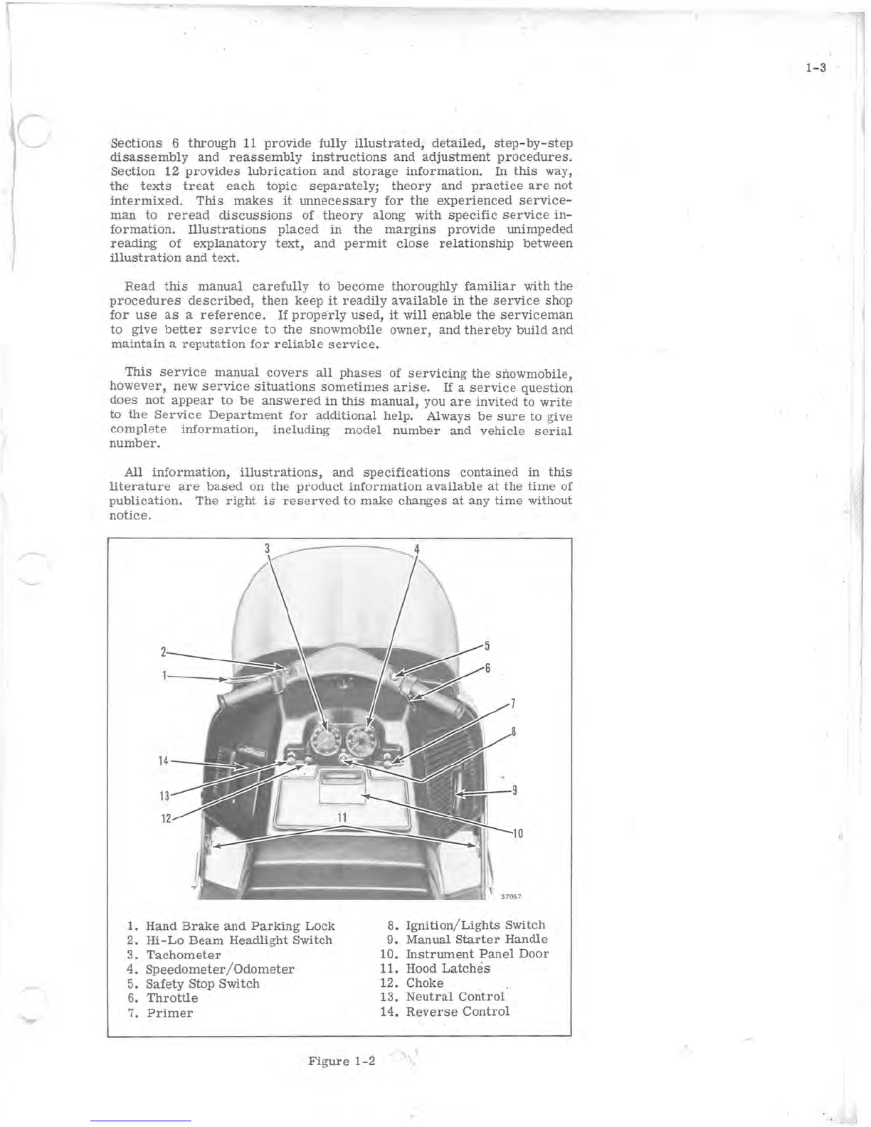
1.
Hand
Brake
and
Parking
Lock
8.
Ignition
/
Lights
Switch
2.
Hi-Lo
Beam
Headlight
Switch
9.
Manual
Starter
Handle
3.
Tachometer
10.
Instrument
Panel
Door
4.
Speedometer/Odometer
11. Hood
Latches
5.
Safety
Stop Switch
6.
Throttle
12. Choke
13.
Neutral
Control
7.
Primer
14.
Reverse
Control
Figure
1-2
1-3

I '
This manual suits for next models
1
Table of contents
Other Evinrude & Johnson Offroad Vehicle manuals


