Evinrude & Johnson E-1532 User manual
1973
~
EVINRUDE
~
~
~
&JOHNSON
SNOWMOBILE
PART
NO
.
406133
r
SECTION
1
INTRODUCTION
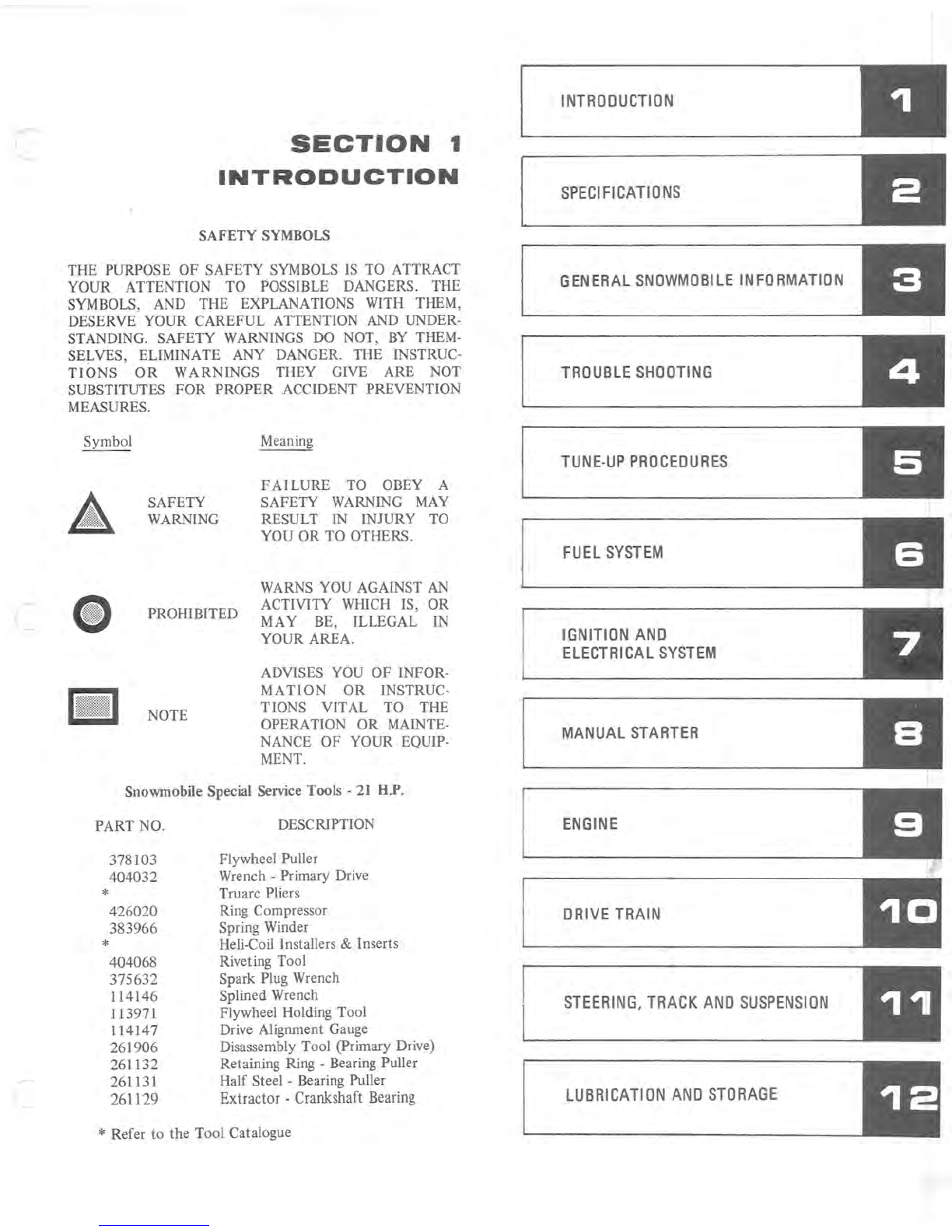
SAFETY SYMBOLS
THE PURPOSE OF SAFETY SYMBOLS
IS
TO ATTRACT
YOUR ATTENTION TO POSSIBLE DANGERS. THE
SYMBOLS, AND THE EXPLANATIONS WITH THEM,
DESERVE YOUR CAREFUL ATTENTION AND UNDER-
STANDING. SAFETY WARNINGS DO NOT,
BY
THEM-
SELVES, ELIMINATE ANY DANGER. THE INSTRUC-
TIONS
OR
WARNINGS
THEY GIVE ARE NOT
SUBSTITUTES
FOR
PROPER ACCIDENT PREVENTION
MEASURES.
Symbol
SAFETY
WARNING
Meaning
FAILURE
TO OBEY A
SAFETY WARNING MAY
RESULT IN INJURY TO
YOU
OR
TO
OTHERS.
• PROHIBITED
WARNS YOU AGAINST
AN
ACTIVITY WHICH IS, OR
MAY BE, ILLEGAL IN
YOUR AREA.
NOTE
ADVISES YOU
OF
INFOR-
MATION
OR
INSTRUC-
TIONS VIT
AL TO THE
OPERATION
OR
MAINTE-
NANCE
OF
YOUR EQUIP-
MENT.
Snowmobile Special Service Tools -
21
H.P.
PART NO.
*
*
378103
404032
426020
383966
404068
375632
114146
113971
114147
261906
261132
261131
261129
DESCRIPTION
Flywheel Puller
Wrench -Primary Drive
Truarc Pliers
Ring Compressor
Spring Winder
Heli-Coil Installers & Inserts
Riveting Tool
Spark Plug Wrench
Splined Wrench
Flywheel Holding Tool
Drive Alignment Gauge
Disassembly Tool (primary Drive)
Retaining Ring -Bearing Puller
Half Steel -Bearing Puller
Extractor -
Crankshaft
Bearing
* Refer to the Tool Catalogue
INTROOUCTION
SPECIFICATIONS
GENERAL
SNOWMOBILE
INFORMATION
TROUBLE
SHOOTING
TUNE-UP
PROCEDURES
FUEL
SYSTEM
IGNITION
AND
ELECTRICAL
SYSTEM
MANUAL
STARTER
ENGINE
~
__
D_R
_
IV_E
__
T_RA
_
I_N
__
________________
~
STEERING,
TRACK
AND
SUSPENSION
LUBRICATION
AND
STORAGE
II
~----.J
1- 2
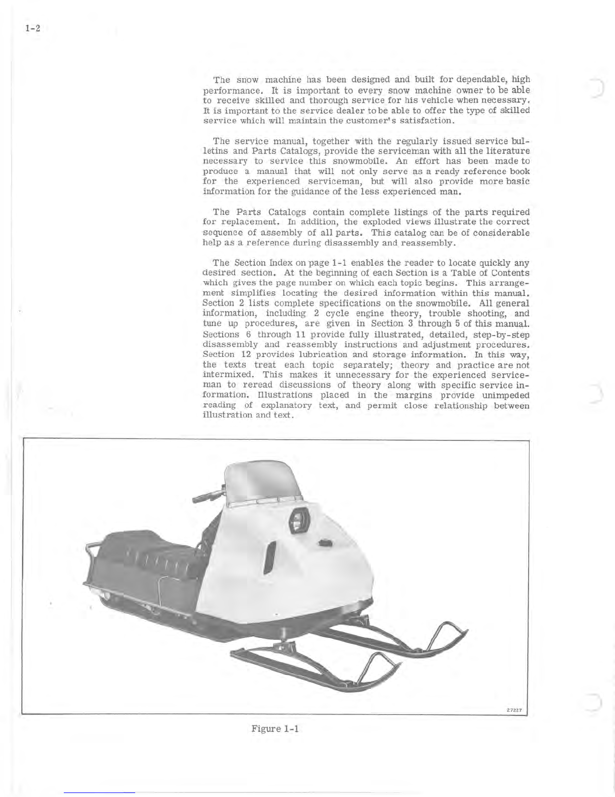
The
snow
machine
has
been
designed
and
built
for
dependable,
high
performance.
It
is
important
to
every
snow
machine
owner
to
be
able
to
receive
skilled
and
thorough
service
for
his
vehicle
when
necessary.
It
is
important
to
the
service
dealer
to
be
able
to
offer
the
type
of
skilled
service
which will
maintain
the
customer's
satisfaction.
The
service
manual,
together
with
the
regularly
issued
service
bul-
letins
and
Parts
Catalogs,
provide
the
serviceman
with
all
the
literature
necessary
to
service
this
snowmobile.
An
effort
has
been
made
to
produce
a
manual
that
will
not only
serve
as
a
ready
reference
book
for
the
experienced
serviceman,
but
will
also
provide
more
basic
information
for
the
guidance
of
the
less
experienced
man.
The
Parts
Catalogs
contain
complete
listings
of
the
parts
required
for
replacement.
In
addition,
the
exploded
views
illustrate
the
correct
sequence
of
assembly
of
all
parts.
This
catalog
can
be
of
considerable
help
as
a
reference
during
disassembly
and
reassembly.
The
Section
Index on
page
1-1
enables
the
reader
to
locate
quickly
any
desired
section.
At
the
beginning
of
each
Section
is
a
Table
of
Contents
which
gives
the
page
number
on
which
each
topic
begins.
This
arrange-
ment
Simplifies
locating
the
desired
information
within
this
manual.
Section
2
lists
complete
specifications
on
the
snowmobile.
All
general
information,
including
2
cycle
engine
theory,
trouble
shooting,
and
tune
up
procedures,
are
given
in
Section
3
through
5 of
this
manual.
Sections
6
through
11
provide
fully
illustrated,
detailed,
step-by-step
disassembly
and
reassembly
instructions
and
adjustment
procedures.
Section
12
provides
lubrication
and
storage
information.
In
this
way,
the
texts
treat
each
topiC
separately;
theory
and
practice
are
not
intermixed.
This
makes
it
unnecessary
for
the
experienced
service-
man
to
reread
discussions
of
theory
along
with
specific
service
in-
formation.
Illustrations
placed
in
the
margins
provide
unimpeded
reading
of
explanatory
text,
and
permit
close
relationship
between
illustration
and
text.
I
27227
Figure
1-1
)

.-
I
I
Read
this
manual
carefully
to
become
thoroughly
familiar
with
the
procedures
described,
then
keep
it
readily
available
in
the
service
shop
for
use
as
a
reference.
If
properly
used,
it
will
enable
the
serviceman
to
give
better
serv~c.e
to
the
snow
machine
owner,
and
thereby
build
and
maintain
a
reputation
for
reliable
service.
This
service
manual
covers
all
phases
of
servicing
the
snowmobile,
however,
new
service
situations
sometimes
arise.
If
a
service
question
does
not
appear
to
be
answered
in
this
manual,
you
are
invited
to
write
to
the
Service
Department
for
additional help.
Always
be
sure
to
give
complete
information,
including
model
number
and
vehicle
identification
number.
All
information,
illustrations,
and
specifications
contained
in
this
literature
are
based
on
the
product
information
available
at
the
time
of
publication.
The
right
is
reserved
to
make
changes
at
any
time
without
notice.
1.
HAND
BRAKE
AND
PARKING LOCK -
To
apply
brake,
squeeze
brake
lever.
NOTE:
Do
not
race
engine
with
brake
applied.
To apply
parking
lock,
with
brake
engaged,
flip
parking
lock
into
po-
sition
as
illustrated
in
Figure
1-2.
To
release,
squeeze
brake
lever.
8
9
;:of-~--4
6
~---5
2--+-~
12
13
Figure
1-2
1-3
1- 4
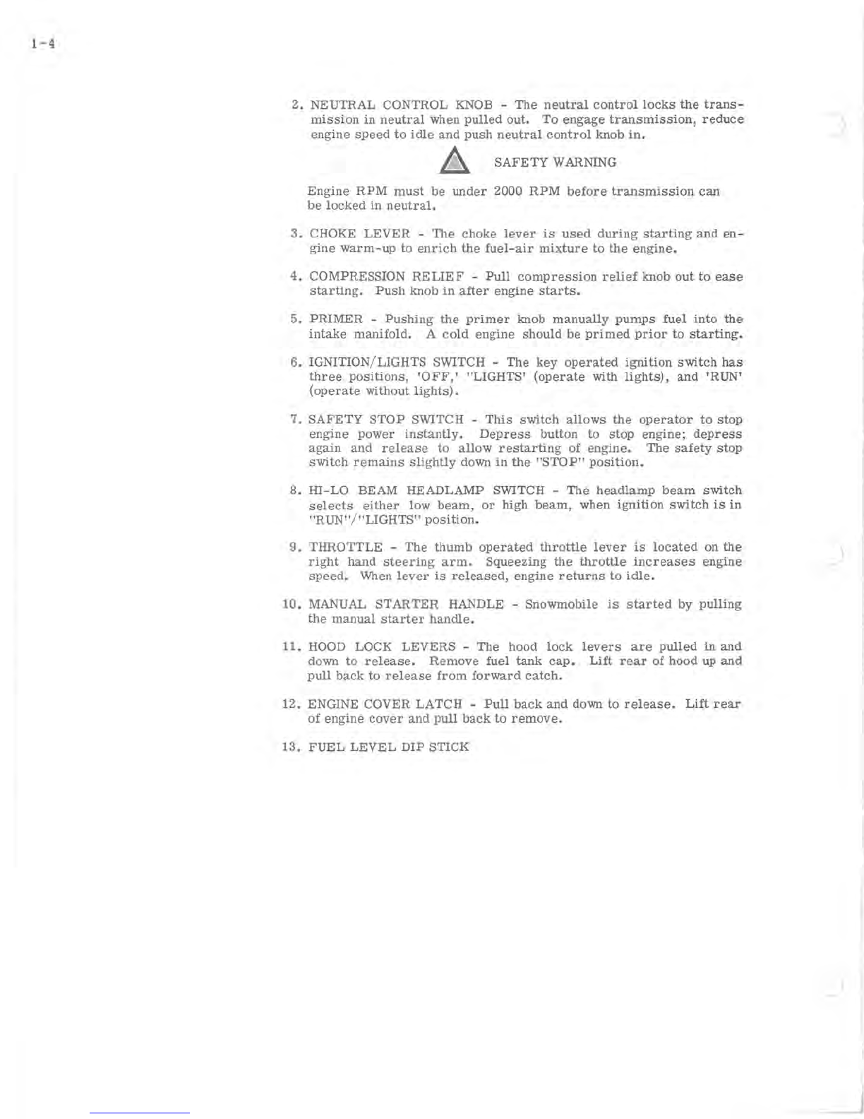
2.
NEUTRAL CONTROL KNOB -
The
neutral
control
locks
the
trans-
mission
in
neutral
when
pulled
out.
To
engage
transmission,
reduce
engine
speed
to
idle
and
push
neutral
control
knob
in.
A
SAFETY
WARNING
Engine
RPM
must
be
under
2000
RPM
before
transmission
can
be
locked
in
neutral.
3.
CHOKE
LEVER
-
The
choke
lever
is
used
during
starting
and
en-
gine
warm-up
to
enrich
the
fuel-air
mixture
to
the
engine.
4.
COMPRESSION
RELIEF
-
Pull
compression
relief
knob
out
to
ease
starting.
Push
knob
in
after
engine
starts.
5.
PRIMER
-
Pushing
the
primer
knob
manually
pumps
fuel
into
the
intake
manifold.
A
cold
engine
should
be
primed
prior
to
starting.
6. IGNITION/LIGHTS SWITCH -
The
key
operated
ignition
switch
has
three
positions,
'OFF,'
"LIGHTS'
(operate
with
lights),
and
'RUN'
(operate
without
lights).
7.
SAFETY
STOP
SWITCH -
This
switch
allows
the
operator
to
stop
engine
power
instantly.
Depress
button
to
stop
engine;
depress
again
and
release
to
allow
restarting
of
engine.
The
safety
stop
switch
remains
slightly
down
in
the
"STOP"
position.
8.
HI-LO
BEAM
HEADLAMP
SWITCH -
The
headlamp
beam
switch
selects
either
low
beam,
or
high
beam,
when
ignition
switch
is
in
"RUN"
/
"LIGHTS"
position.
9.
THROTTLE
-
The
thumb
operated
throttle
lever
is
located
on
the
right
hand
steering
arm.
Squeezing
the
throttle
increases
engine
speed.
When
lever
is
released,
engine
returns
to
idle.
10.
MANUAL
STARTER
HANDLE -
Snowmobile
is
started
by
pulling
the
manual
starter
handle.
11.
HOOD LOCK
LEVERS
-
The
hood
lock
levers
are
pulled
in
and
down
to
release.
Remove
fuel
tank
cap.
Lift
rear
of
hood
up
and
pull
back
to
release
from
forward
catch.
12.
ENGINE COVER
LATCH
-
Pull
back
and
down
to
release.
Lift
rear
of
engine
cover
and
pull
back
to
remove.
13.
FUEL
LEVEL
DIP
STICK

SECTION
2
SPECIFICATIONS
TABLE
OF
CONTENTS
SPECIFICATIONS
...
.
....................
2-2
TORQUE
SPECIFICATIONS.
. . . . . . . . . . . . . . .
..
2-3
2-1
2-2
For
your
own
protection,
before
proceeding
with any
repair
or
adjustments
on
these
snow-
mobiles,
see
4
SAFETY
WARNING
on
inside
front
cover
and
pages
1-4,
6-7,
7-5,
7-6,
8-2,
9-5,
10-2, 10-3,
11-4
and
12-4.
SPECIFICATIONS
(i)
PROillBITED
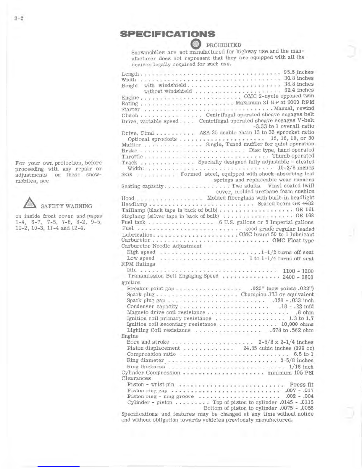
Snowmobiles
are
not
manufactured
for
highway
use
and
the
man-
ufacturer
does
not
represent
that
they
are
equipped
with
all
the
devices
legally
required
for
such
use.
Length.
. . . . . . . . . . . . . . . . . . . . . . . . . . . . . . .
95.5
inches
Width
.............
..........
30.8'
inches
Height
with
windshield.
. . . . . . . . . .
-'-
. . . . . 38.8
inches
without
windshield
. . . . . . . . . . . . . 32.4
inches
Engine.
. . . . . . . . . . . . . . . . . . . . . . . . . OMC
2-cycle
opposed
twin
Rating
........................
Maximum
21
HP
at
6000
RPM
Starter
........
.
.. ..
....................
Manual,
rewind
Clutch
. . . . . . . . . . . . . . . .
Centrifugal
operated
sheave
engages
belt
Drive,
variable
speed.
.
..
Centrifugal
operated
sheave
engages
V
-belt
-3.33
to
1
overall
ratio
Drive,
Final.
. . . . . . .
•.
ASA
35
double
chain
13
to
33
sprocket
ratio
Optional
sprockets
•.•.•.••••....••••....
. 15, 16, 18,
or
30
Muffler
..
. . . . . . . . . . .
..
Single,
Tuned
muffler
for
quiet
operation
Brake
. . . . . . . . . . . . . . . . . . . .
..
Disc
type,
hand
operated
Throttle.
. . . . . . . . . . . . . . . . . . . . . . . . . . .
Thumb
operated
Track
. . . . . . . . .
..
Specially
designed
fully
adjustable
-
cleated
Width:
.......
. . . . . . . . . . . . . . . .
..
15-3/8
inches
Skis
..
..
......
Formed
steel,
equipped
with
shock-absorbing
leaf
Seating
capacity
. .
springs
and
replaceable
wear
runners
.....
. . Two
adults.
Vinyl
coated
twill
cover,
molded
urethane
foam
cushion
Hood.
. . . . . . . . Molded
fiberglass
with
built-in
headlight
Headlamp.
. . . . . . . . . . . . . . . . . . . . . • • .
•.
Sealed
beam
GE 4482
Taillamp
(black
tape
in
back
of
bulb)
.••.•...•••.•..•.•.
GE 161
Stop
lamp
(silver
tape
in
back
of bulb) .
.•••....•••.••••..
GE 168
Fuel
tank.
. . . . . . . . . . . . . .
..
6 U.S.
gallons
or
5
Imperial
gallons
Fuel
. . . . . . . . . . . . . . . . . . . . . . . . .
..
good grad-e
regular
leaded
Lubrication
......................
OMC
brand
50
to
1
lubricant
Carburetor
. . . . . . . . . . . . . . . . . . . . . OMC
Float
type
Carburetor
Needle
Adjustment
High
speed
.
.....
.
Low
speed
..
. . .
.....
.
RPM
Ratings
.
....
1-1
/ 2
turns
off
seat
. 1
to
1-1/4
turns
off
seat
Idle
...........
.
....
. . . . . . .
..
1100 -1200
Transmission
Belt
Engaging
Speed
.••..••••.•....
2400 -2800
Ignition
Breaker
point
gap.
. . . . . . . . . . . . . .
..
.020"
(new
points
.022")
Spark
plug.
. . . . . . . .
..
Champion
J7J
or
equivalent
Spark
plug
gap . . . . . . . . . . . .
.028
-
.033
inch
Condenser
capacity
. . . . . . . . . . . . . . . . . . .
.18
-
.22
mfd
Magneto
drive
coil
resistance.
. . . . . . . . . . .
.8
ohm
Ignition
coil
primary
resistance
.............
. . .
..
1. 3
to
1.7
Ignition
coil
secondary
resistance
. . . . . . . . . . . . .
..
10,000
ohms
Lighting
Coil
resistance
.678
to
.562
ohm
Engine
Bore
and
stroke
. . . .
2-5/8
x
2-1/4
inches
Piston
displacement
. 24.35
cubic
inches
(399 cc)
Compression
ratio
..
. . . . . . . . . .
..
6.5
to
1
Ring
diameter.
. . . . . . . . . . . . . . . . . . . .
..
2-5/8
inches
Ring
thickness
. . . . . . . . . . . . . . . . . . . . . . . . . . . .
..
1/16
inch
Cylinder
Compression
. . . • . • • • • • • • . • • . • . •
••
minimum
105
PSI
Clearances
Piston -
wrist
pin
.............•........•....
Press
fit
Piston
ring
gap
........•.•.........••.••.••
.007 -.017
Piston
ring
-
ring
groove
..•.•••..•........•..
.002 -.004
Cylinder
-
piston
...••....
Top of
piston
to
cylinder
.0145 -.0115
Bottom
of
piston
to
cylinder
.0075 -.0055
Specifications
and
features
may
be
changed
at
any
time
without
notice
and
without
obligation
towards
vehicles
previously
manufactured.
J
)
.J
c
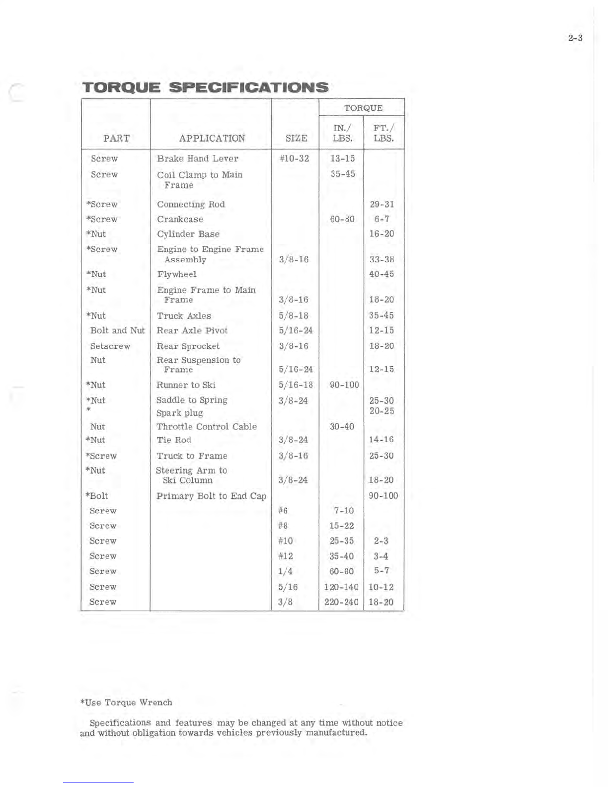
TORQUE
SPECIFICATIONS
TORQUE
IN./
FT./
PART
APPLICATION SIZE LBS. LBS.
Screw
Brake
Hand
Lever
#10-32 13-15
Screw
Coil
Clamp
to
Main 35-45
Frame
*Screw
Connecting
Rod 29-31
*Screw
Crankcase
60-80
6-7
*Nut
Cylinder
Base
16-20
*Screw
Engine to Engine
Frame
Assembly
3/8-16
33-38
*Nut
Flywheel
40-45
*Nut Engine
Frame
to Main
Frame
3/8-16
18-20
*Nut
Truck
Axles
5/8-18
35-45
Bolt
and
Nut
Rear
Axle
Pivot
5/16-24 12-15
Setscrew
Rear
Sprocket
3/8-16
18-20
Nut
Rear
Suspension
to
Frame
5/16-24 12-15
*Nut
Runner
to Ski 5/16-18 90-100
*Nut
Saddle
to
Spring
3/8-24
25-30
*
Spark
plug
20-25
Nut
Throttle
Control
Cable
30-40
*Nut
Tie
Rod
3/8-24
14-16
*Screw
Truck
to
Frame
3/8-16
25-30
*Nut
Steering
Arm
to
Ski Column
3/8-24
18-20
*Bolt
Primary
Bolt
to End Cap 90-100
Screw
#6
7-10
Screw
#8
15-22
Screw
#10 25-35 2-3
Screw
#12 35-40 3-4
Screw
1/4
60-80
5-7
Screw
5/16 120-140 10-12
Screw
3/8
220-240 18-20
*Use
Torque
Wrench
Specifications
and
features
may
be
changed
at
any
time
without
notice
and
without
obligation
towards
vehicles
previously
manufactured.
2-3

.J
..,;) I

SECTION
3
GENERAL
SNOWMOBILE
INFORMATION
TABLE
OF
CONTENTS
TWO-CYCLE
ENGINE
THEORY
••.•••••••••.••
3-2
COMPRESSION • • • • • • • . . . • . • • • • • • . . • • • •
••
3-2
SPARK
PLUGS
••••••••••••••.•••••••••••
3-3
CARBURETION
• • • • • • . . . • • • • • . . • . • . • • • •
.•
3-4
IGNITION.
• • • • • • • • • • . . . • . . • • • • • • • • . • •
..
3-4
POWER
FLOW
••••••••••••
••.•••••••••••
3-5
PRIMARY
DRIVE
••••••.•••••••••••••••
3-5
SECONDARY DRIVE
..•••.•••.•••.••••••
3-5
3-1
II

3-2
POWER
STROKE
-
DOWN
COMBUSTION
OF
ROD
BALANCE
AXIS
OF
ROTATION
Figure
3-1
17133
FUEL
INTAKE
+
EXHAUST
LEAF
VALVES
EXHAUST
PORT
OPEN
Figure
3-2
17134
COMPRESSION
STROKE
-
UP
FUEL
FROM
EXHAUST
PORT
CLOSED
Figure
3-3
17135
TWO
CYCLE
ENGINE
THEORY
An
internal
combustion
engine
is
one
in
which
fuel
is
burned
inside
the
engine:
a
charge
of
fuel
is
introduced
into
a
combustion
chamber
(cyl-
inder)
within
the
engine
and
ignited.
The
energy
released
by
the
expan-
sion
of
the
burning
fuel
is
converted
to
torque
by the
piston,
connecting
rod,
and
crankshaft.
Internal
combustion
engines
are
classified
as
either
four-cycle
or
two-cycle
engines.
The
"four"
and
the
"two"
refers
to
the
number
of
piston
strokes
required
to
complete
a
power
cycle
of
intake,
compres-
sion,
power,
and
exhaust.
A
piston
stroke
is
piston
travel
in
one
direc-
tion
only;
up
is
one
stroke,
down
is
another.
In a
four-cycle
engine,
two
crankshaft
revolutions,
or
four
strokes,
are
required
for
each
power
cycle.
In a
two-cycle
engine
only one
crankshaft
revolution
is
required
per
power
cycle.
In a
two-cycle
engine,
the
ignition
of
the
fuel-air
mixture
occurs
as
the
piston
reaches
the
top
of
each
stroke.
The
expansion
of
gases
drives
the
piston
downward
(see
Figure
3-1).
Toward
the
end of
the
downward
stroke,
ports
which
lead
from
the
cylinder
to
the
exhaust
system
are
uncovered.
The
expanding
exhaust
gases
flow
into
these
ports,
re-
ducing
pressure
in
the
cylinder.
Immediately
after,
intake
ports
are
opened.
These
ports
cOlmect
the
cylinder
with
the
crankcase
where
a
mixture
of
fuel
and
air
has
been
developed
by
carburetion.
The
down-
ward
motion
of
the
piston
compresses
this
mixture
and
forces
it
through
the
intake
ports
into
the
cylinder.
(See
Figure
3-2.)
The
inrushing
charge
of the
fuel-air
mixture
helps
to
eject
(scavenge)
the
last
of
the
exhaust
gases
from
the
cylinder.
At
this
point,
the
momentum
of
the
flywheel
is
required
to
return
the
piston
to
the
top of
the
cylinder.
As
the
piston
begins
its
up-
stroke,
it
closes
the
intake
and
exhaust
ports
and
begins
to
compress
the
fuel-air
mixture
trapped
in
the
cylinder
(see
Figure
3-3).
The
upward
motion
of
the
piston
also
reduces
the
pressure
in
the
crankcase.
The
tesulting
crankcase
suction
opens
leaf
valves
which
admit
a
fresh
charge
of
air
and
fuel
from
the
carburetor
into
the
crankcase,
thus
preparing
for
the
next
power
cycle.
Near
the
top of
the
piston
stroke,
the
compressed
fuel-air
mixture
is
ignited,
the
piston
is
driven
downward,
and
the
power
cycle
is
repeated.
At full
throttle,
this
cycle
may
be
repeated
more
than
five
thousand
times
every
minute.
COMPRESSION
The
pistons
and
piston
rings
perform
two
functions.
They
compress
the
mixture
of fuel
and
air
in
the
cylinders
before
ignition,
and
receive
the
force
of
the
power
after
ignition.
For
maximum
compression,
the
cylinder
must
be
round
and
the
piston
and
piston
rings
correctly
fitted
to
it.
The
rings
must
be
properly
seated
in
the
ring
grooves
and
free
to
expand
against
the
walls
of
the
cylinder.
The
rings
will
not
retain
the
pressure
of
combustion
if
the
pistons
and
cylinder
walls
are
exces-
sively
worn,
scored,
or
otherwise
damaged,
or
if
the
rings
become
stuck
in
grooves
because
of
carbon
build
up.
Escape
of
compression
past
the
piston
rings
is
referred
to
as
"blow-by"
and
is
indicated
by
discolora-
tion
or
carbon
formation
on
the
piston
skirt.
Cylinder
bores
normally
wear
with
operation
of
the
engine.
The
de-
gree
of
wear
will
vary
with
length
of
operation,
efficiency
of
lubrication,
and
general
condition
of
the
engine.
Excessive
cylinder
wear
results
in
loose
fitting
pistons
and
rings,
causing
blow-by,
loss
of
compression,
loss
of
power
and
inefficient
performance.
Piston
rings
are
formed
in
such
a
manner
that
when
installed
on
the
piston,
they
bear
against
the
cylinder
wall
with a
light,
even
pressure.
Excessive
ring
pressure
against
the
cylinder
wall
increases
friction,
)

(
causing
high
operating
temperature,
sluggish
performance,
and
abnor-
mal
wear
or
scoring.
Insufficient
pressure
allows
blow-by,
which
re-
duces
power,
and
causes
overheating
and
carbon
formation
on the
piston
skirt.
Since
the
ring
tends
to
flex
as
it
follows
the
cylinder
contour
during
engine
operation,
clearance
or
gap
must
be
provided
between
the
ring
ends
to
prevent
butting.
The
ring
gap
also
allows
the
ring
to
expand
(elongate)
as
engine
temperature
rises
during
operation.
Insufficient
gap
clearance
will
cause
the
ring
to
bend
or
warp
as
it
flexes
and
ex-
pands;
excessive
gap
clearance
will
permit
loss
of
compression.
Compression
leakage
may
also
occur
at
the
spark
plugs.
A
cracked
spark
plug
insulator
will
cause
similar
trouble.
Although
compression
is
primarily
dependent
on
the
piston,
rings,
and
cylinder,
these
other
sources
of
leakage
should
be
investigated
when
compression
loss
is
noted.
Compression
may
also
be
affected
by
the
fuel
induction
and
exhaust
systems.
Since
the
fuel
vapor
is
first
compressed
in
the
crankcase,
leakage
here
will
affect
engine
performance.
Possible
trouble
spots
include
leaf
valve
assemblies,
seals
between
crankcase
halves,
and
crankshaft
bearing
seals.
Exhaust
ports
which
have
become
clogged
because
of
excessive
deposits
of
carbon
will
hinder
the
efficient
transfer
of
exhaust
gases.
Excessive
carbon
build-up
on
piston
heads
or
elsewhere
in
the
cyl-
inder
walls
can
result
in
a
loss
of
power.
Following
the
trouble
check
chart
provided
at
the end of
this
section
and
the
recommended
tune-up
procedures
given
in
Section
will
assure
that
all
areas
affecting
fuel
induction,
compression,
and
exhaust
will
be
considered
as
part
of
every
trouble
shooting
procedure.
An
engine
with
low
or
uneven
compression
cannot
be
successfully
tuned
for
peak
per-
formance.
It
is
essential
that
improper
compression
be
corrected
be-
fore
proceeding
with an
engine
tune-up.
SPARK
PLUGS
The
spark
plug
provides
a gap
inside
the
combustion
chamber
across
which
the
high
voltage
from
the
ignition
coil
can
be
discharged.
The
resulting
spark
ignites
the
compressed
mixture
of
fuel
vapor
and
air
in
the
cylinder.
See
Figure
3
-4.
Spark
plugs
are
made
in
a
number
of
heat
ranges
to
satisfy
a
variety
of
operating
conditions.
The
heat
range
of a
spark
plug
refers
to
its
ability
to
dissipate
heat
from
its
firing
end
to
the
cylinder
head.
The
heat
range
established
for
any
spark
plug
is
determined
in
design
by
the
length
of
the
path
which
the
heat
from
the
tip
must
travel
to
the
thread
and
seat
area
where
it
is
transferred
to
the
cylinder.
Spark
plugs
having
a
short
gap
between
the
firing
end of
the
center
electrode
and
the
thread
and
seat
area
are
used
for
hot
running
engines
(see
Figure
3-5).
Snowmobiles
used
in
heavy
load
conditions
(ie.
deep
snow
or
sled
towing)
will
run
the
engine
temperature
higher,
and
in
this
case,
a
colder
plug
might
be
recommended.
Spark
plugs
operating
under
these
conditions
must
remain
cool
enough
to
avoid
preignition
and
excessive
gap
erosion.
Spark
plugs
having
a long gap
transfer
heat
slower
and
are
used
on
cooler
running
engines.
See
Figure
3-6.
Cooler
running
en-
gines
have
a
relatively
low
combustion
chamber
temperature,
therefore
a high
spark
plug
temperature
must
be
sustained
in
order
to
burn
off
normal
combustion
deposits
and
avoid
fouling.
For
most
effective
sparking
through
any
rpm
range
and
under
all
conditions
of
operation,
the
electrode
and
insulator
tip
temperature
must
be
kept
high
enough
to
vaporize
or
burn
off
particles
of
fuel
mixture
which
collect
on
the
insulator.
Low
plug
temperatures
result
in
electrode
fouling by
an
accumulation
of
unburned
fuel
particles,
carbon
bits,
Sludge,
etc.
Se-
lection
of
the
correct
spark
plugs
for
an
engine
depends
on
the
type
of
service
to
which
it
will
be
subjected.
A
cold
running
engine
will
require
a hot
plug
and a hot
running
engine,
a
cold
plug.
See
Section
7
for
additional
information
on
spark
plugs.
3-3
GROUND
CENTER
ELECTRODE
17
138
Figure
3-4
COOL
PLUG
17139
Figure
3-5
HOT
PLUG 17
140
Figure
3-6
3-4
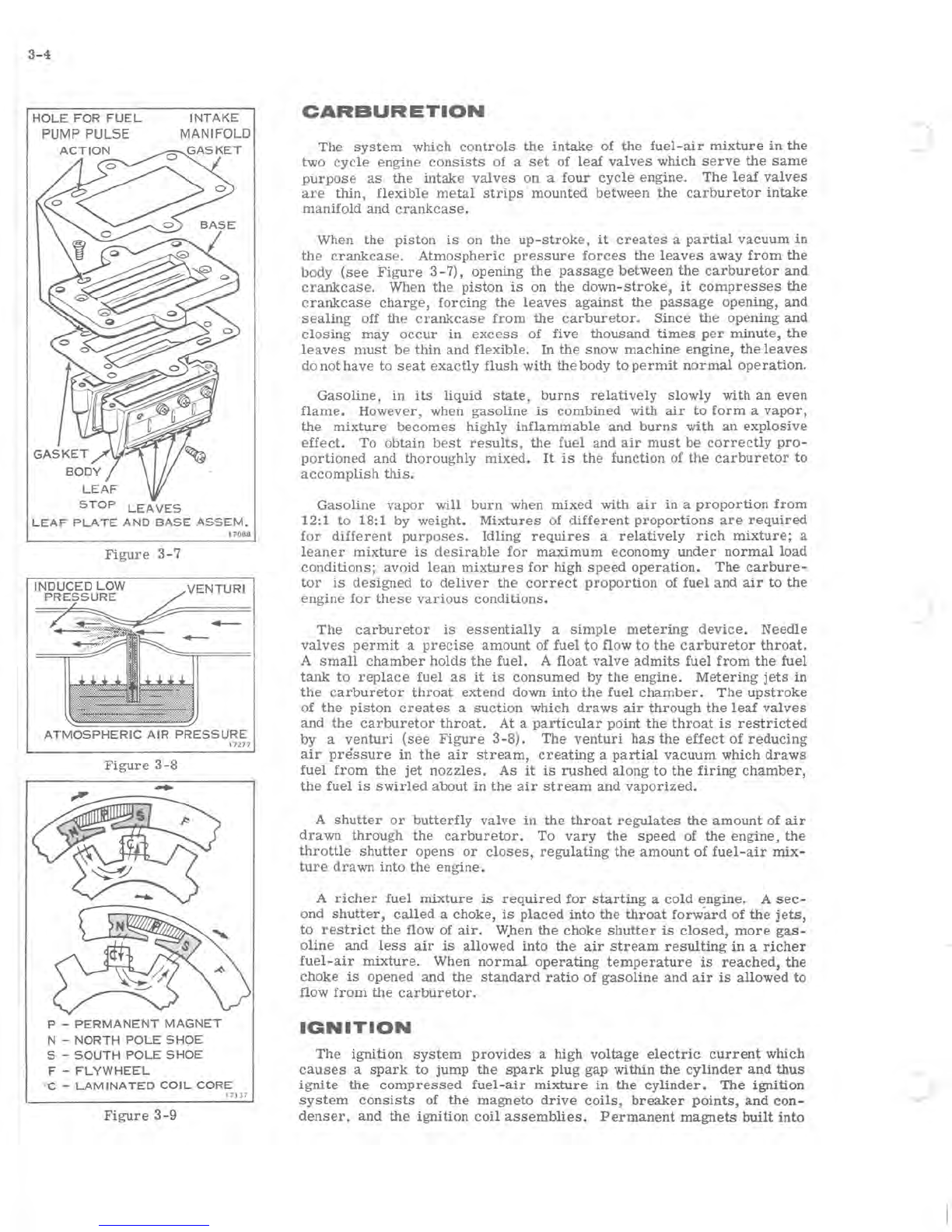
HOLE
FOR
FUEL
PUMP PULSE
INTAKE
MANIFOLD
STOP
LEAVES
LEAF
PLATE
AND
BASE
ASSEM.
17088
Figure
3-7
ATMOSPHERIC
AIR
PRESSURE
Figure
3-8
P -
PERMANENT
MAGNET
N -
NORTH
POLE
SHOE
S -
SOUTH
POLE
SHOE
F -
FLYWHEEL
1727
7
~
C -
LAMINATED
COIL
CORE
17 1
37
Figure
3-9
CARBURETION
The
system
which
controls
the
intake
of
the
fuel
-
air
mixture
in
the
two
cycle
engine
consists
of a
set
of
leaf
valves
which
serve
the
same
purpose
as
the
intake
valves
on
a
four
cycle
engine.
The
leaf
valves
are
thin,
flexible
metal
strips
mounted
between
the
carburetor
intake
manifold
and
crankcase.
When
the
piston
is
on the
up-stroke,
it
creates
a
partial
vacuum
in
the
crankcase.
Atmospheric
pressure
forces
the
leaves
away
from
the
body
(see
Figure
3
-7),
opening
the
passage
between
the
carburetor
and
crankcase.
When
the
piston
is
on
the
down-stroke,
it
compresses
the
crankcase
charge,
forcing
the
leaves
against
the
passage
opening,
and
sealing
off
the
crankcase
from
the
carburetor.
Since
the
opening
and
closing
may
occur
in
excess
of five
thousand
times
per
minute,
the
leaves
must
be
thin
and
flexible.
In
the
snow
machine
engine,
the
leaves
do not
have
to
seat
exactly
flush
with
the
body
to
permit
normal
operation.
Gasoline,
in
its
liquid
state,
burns
relatively
slowly
with
an
even
flame.
However,
when
gasoline
is
combined
with
air
to
form
a
vapor,
the
mixture
becomes
highly
inflammable
and
burns
with
an
explosive
effect.
To
obtain
best
results,
the
fuel
and
air
must
be
correctly
pro-
portioned
and
thoroughly
mixed.
It
is
the
function of
the
carburetor
to
accomplish
this.
Gasoline
vapor
will
burn
when
mixed
with
air
in
a
proportion
from
12:1 to 18:1 by weight.
Mixtures
of
different
proportions
are
required
for
different
purposes.
Idling
requires
a
relatively
rich
mixture;
a
leaner
mixture
is
desirable
for
maximum
economy
under
normal
load
conditions;
avoid
lean
mixtures
for
high
speed
operation.
The
carbure-
tor
is
designed
to
deliver
the
correct
proportion
of
fuel
and
air
to
the
engine
for
these
various
conditions.
The
carburetor
is
essentially
a
simple
metering
device.
Needle
valves
permit
a
precise
amount
of
fuel
to
flow
to
the
carburetor
throat.
A
small
chamber
holds
the
fuel.
A
float
valve
admits
fuel
from
the
fuel
tank
to
replace
fuel
as
it
is
consumed
by
the
engine.
Metering
jets
in
the
carburetor
throat
extend
down into
the
fuel
chamber.
The
upstroke
of
the
piston
creates
a
suction
which
draws
air
through
the
leaf
valves
and
the
carburetor
throat.
At a
particular
point
the
throat
is
restricted
by a
venturi
(see
Figure
3-8).
The
venturi
has
the
effect
of
reducing
air
pressure
in
the
air
stream,
creating
a
partial
vacuum
which
draws
fuel
from
the
jet
nozzles.
As
it
is
rushed
along
to
the
firing
chamber,
the
fuel
is
swirled
about
in
the
air
stream
and
vaporized.
A
shutter
or
butterfly
valve
in
the
throat
regulates
the
amount
of
air
drawn
through
the
carburetor.
To
vary
the
speed
of the
engine,
the
throttle
shutter
opens
or
closes,
regulating
the
amount
of
fuel-air
mix-
ture
drawn
into
the
engine.
A
richer
fuel
mixture
is
required
for
starting
a
cold
engine.
A
sec-
ond
shutter,
called
a
choke,
is
placed
into
the
throat
forward
of
the
jets,
to
restrict
the
flow of
air.
W.hen
the
choke
shutter
is
closed,
more
gas-
oline
and
less
air
is
allowed
into
the
air
stream
resulting
in
a
richer
fuel-air
mixture.
When
normal
operating
temperature
is
reached,
the
choke
is
opened
and
the
standard
ratio
of gaSOline
and
air
is
allowed
to
flow
from
the
carburetor.
IGNITION
The
ignition
system
provides
a high
voltage
electric
current
which
causes
a
spark
to
jump
the
spark
plug
gap within
the
cylinder
and
thus
ignite
the
compressed
fuel-air
mixture
in
the
cylinder.
The
ignition
system
consists
of
the
magneto
drive
coils,
breaker
pOints,
and
con-
denser,
and
the
ignition
coil
assemblies.
Permanent
magnets
built
into
.J
r
the
flywheel
revolve
around
the
magneto
drive
coils.
As
the
magnet
moves
past
the
coils,
the
direction
of
the
magnetic
flux
through
the
coil
is
changed
from
one
direction
to
the
other
(see
Figure
3-6).
Self
-
inductance
of
the
magneto
drive
coil
circuit,
completed
through
the
breaker
points,
prevents
the
flux
in
the
coil
laminations
from
changing
until
the
breaker
points
open.
When
the
pOints open,
the
flux
changes
direction
very
rapidly,
inducing
a
current
which flows
through
the
ignition
coils'
primary
windings.
The
ignition
coils
transform
this
cur-
rent
to
a
very
high
voltage
which
is
suffiCient
to
discharge
across
the
spark
plugs'
gap.
The
lighting
system
coils
produce
alternating
current
which
changes
in
frequency
and
voltage
in
proportion
to
the
engine
speed.
PO
WER
FLOW
The
transmission
assembly
transmits
power
from
the
engine
to
the
front
axle
which
propels
the
vehicle
along
the
track.
The
primary
sheave
assembly
is
attached
directly
to
the
crankshaft.
The
secondary
sheave
assembly
is
mounted
on
the
chain
case
and
is
larger
in
diameter
than
the
primary
assembly.
The
two
are
connected
by
a
transmission
belt.
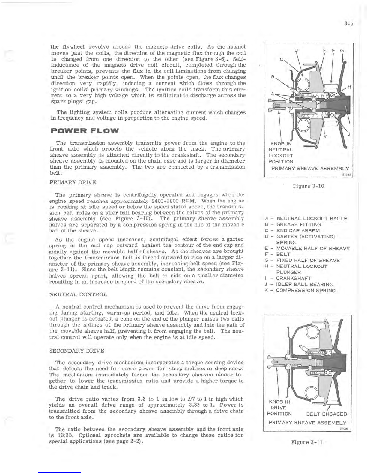
PRIMARY
DRIVE
The
primary
sheave
is
centrifugally
operated
and
engages
when
the
engine
speed
reaches
approximately
2400-2800
RPM.
When
the
engine
is
rotating
at
idle
speed
or
below
the
speed
stated
above,
the
transmis-
sion
belt
rides
on
a
idler
ball
bearing
between
the
halves
of
the
primary
sheave
assembly
(see
Figure
3-10).
The
primary
sheave
assembly
halves
are
separated
by a
compression
spring
in
the
hub of
the
movable
half
of
the
sheave.
As
the
engine
speed
increases,
centrifugal
effect
forces
a
garter
spring
in
the
end
cap
outward
against
the
contour
of
the
end
cap
and
axially
against
the
movable
half
of
sheave.
As
the
sheaves
are
brought
together
the
transmission
belt
is
forced
outward
to
ride
on a
larger
di
-
ameter
of
the
primary
sheave
assembly,
increasing
belt
speed
(see
Fig-
ure
3-11).
Since
the
belt
length
remains
constant,
the
secondary
sheave
halves
spread
apart,
allowing
the
belt
to
ride
on a
smaller
diameter
resulting
in
an
increase
in
speed
of
the
secondary
sheave.
NEUTRAL
CONTROL
A
neutral
control
mechanism
is
used
to
prevent
the
drive
from
engag-
ing
during
starting,
warm
-up
period,
and
idle.
When
the
neutral
lock-
out
plunger
is
actuated,
a
cone
on
the
end
of
the
plunger
raises
two
balls
through
the
splines
of
the
primary
sheave
assembly
and
into
the
path
of
the
movable
sheave
half,
preventing
it
from
engaging
the
belt.
The
neu-
tral
control
will
operate
only when
the
engine
is
at
idle
speed.
SECONDARY
DRIVE
The
secondary
drive
mechanism
incorporates
a
torque
sensing
device
that
detects
the
need
for
more
power
for
steep
inclines
or
deep
snow.
The
mechanism
immediately
forces
the
secondary
sheaves
closer
to-
gether
to
lower
the
transmission
ratio
and
provide
a
higher
torque
to
the
drive
chain
and
track.
The
drive
ratio
varies
from
3.3
to
1
in
low
to
.97
to
1
in
high
which
yields
an
overall
drive
range
of
apprOximately
3.33
to
1.
Power
is
transmitted
from
the
secondary
sheave
assembly
through
a
drive
chain
to
the
front
axle.
The
ratio
between
the
secondaT-Y
sheave
assembly
and
the
front
axle
is
13:33.
Optional
sprockets
are
available
to
change
these
ratios
for
special
applications
(see
page
2
-2).
3-5
D E F G
NE
UTRAL
LOCKOUT
POSITION
PRIMARY
SHEAVE
ASSEMBLY
37028
Figure
3-10
A -
NEUTRAL
LOCKOUT
BALLS
B -
GREASE
FITTING
C -
END
CAP
ASSEM
D -
GARTER
(ACTIVATING)
SPRING
E -
MOVABLE
HALF
OF
SH
E
AVE
F -
BELT
G -
FIXED
HALF
OF
SHEAVE
H -
NEUTRAL
LOCKOUT
PLUNGER
I -
CRANKSHAFT
J -
IDLER
BALL
BEARING
K -
COMPRESSION
SPRING
DRIVE
POSITION
BELT
ENGAGED
PRIMARY
SHEAVE
ASSEMBLY
37029
Figure
3-11

)
-) \
- 1
\
,
\
1
1
I
/
SECTION
4
TROUBLE
SHOOTING
TABLE
OF
CONTENTS
DESCRIPTION
............................
4-2
TROUBLE
SHOOTING
PROCEDURES
.............
4-2
STARTING
...........................
4-2
STARTING
-MANUAL
STARTER
............
4-3
RUNNING -LOW
SPEED
ONLY
.............
4-3
RUNNING -HIGH
SPEED
ONLY
......•......
4-3
RUNNING -HIGH AND LOW
SPEED
..........
4-4
4-1
4-2
DESCRIPTION
This
section
provides
trouble
shooting
procedures
for
the
snow
machine.
Steps
to
be
followed
in
de
-
termining
causes
of
unsatisfactory
performance
are
outlined.
Being
able
to
locate
the
cause
of
trouble
in
an
im
-
properly
operating
snow
machine
is
as
important
as
being
able
to
correct
the
trouble.
A
systematic
ap-
proach
to
trouble
shooting
is
important
if
the
trouble
is
to
be
located
and
identified
in
minimum
time.
Any
service
operation
can
be
broken
down
into
three
steps:
1.
Identifying
the
problem
2.
Determining
the
cause
of
the
problem,
and
3.
Correcting
the
problem.
Familiarity
with
the
factors
which
affect
two-
cycle
engine
performance
is
important
in
making
a
correct
service
diagnosis.
Factors
which
affect
engine
per-
formance
include
the
quality
of
the
fuel
and
'fuel
mix-
tures,
compression,
spark
and
spark
plug
operation,
and
proper
drive
system
adjustment.
This
section
discusses
compression
and
spark
plugs
and
their
re-
lation
to
performance.
A
complete
discussion
of
fuel
mixtures
is
included
in
Section
12.
Familiarity
with
factors
which
contribute
to
abnormal
perform-
ance
of
an
engine
are
similarly
helpful.
The
skilled
mechanic's
experience
is
a
great
asset
here.
TROUBLE
SHOOTING
PROCEDURES
Trouble
shooting
to
determine
the
cause
of
any
operating
problem
may
be
broken
down
into
the
following
steps:
a.
Obtaining
an
accurate
description
of
the
trouble.
b.
Quick
tune-up.
An
accurate
description
of
the
trouble
is
essential
for
trouble
shooting.
The
owner's
comments
may
provide
valuable
information
which
will
serve
as
a
clue
to
the
cause
of
the
problem.
Find
out
pertinent
facts
such
as:
a.
Correct
spark
plugs
b.
Throttle
linkage
properly
adjusted
c.
Tank
filled
with
fresh,
clean
fuel
of
the
proper
mixture
d.
Spark
at
each
spark
plug
e.
Carburetor
adjusted
correctly
f.
Turn
flywheel
by hand
or
with
recoil
starter.
If
compression
is
present,
it
can
be
felt
when
turning
through
one
complete
revolution
of
the
flywheel.
If
little
or
no
compression
exists
in
both
cylinders,
engine
will
spin
very
easily.
STARTING
1.
Hard
to
start
or
won't
start
a.
Empty
gas
tank
b.
Incorrect
gas-lubricant
ratio
c.
Old
fuel,
or
water
or
dirt
in
fuel
system
d.
Fuel
line
improperly
connected
e.
Fuel
line
kinked
or
severely
pinched
f.
Clogged
fuel
line
or
fuel
pick
up
in
tank
g.
Clogged
check
valve
h.
Carburetor
adjustments
too
lean
i.
High
speed
needle
bent
or
bowed
j.
Leaf
valves
not
functioning
properly
k.
Faulty
gaskets
1.
Spark
plugs
fouled,
improperly
gapped,
dirty
or
broken
m.
Loose
or
broken
wire
or
frayed
insulation
in
electrical
system
n.
Sheared
flywheel
key
o.
Faulty
coils
p.
Faulty
condenser
q. Binding
in
engine
r.
Weak
or
reversed
polarity
of
flywheel
magnets
s.
Engine
flooded
t.
Engine
not
primed
2.
Engine
won't
crank
over
a.
Cylinder
wall
corrosion
b.
Broken
connecting
rod,
crankshaft,
or
drive
shaft
c.
Engine
improperly
assembled
after
repair
3.
Cranks
over
extremely
easily
a.
Spark
plug
loose
r
b.
Cylinder
or
pistons
scored
c.
Hole
burned
in
piston
head
d.
Rings
worn
4.
Won't
start,
but
kicks
back
and
backfires
a.
Flywheel
key
sheared
b.
Timing
out
of
adjustment
c.
Leaf
valves
broken
or
not
seating
STARTING
-MANUAL
STARTER
1.
Manual
starter
pulls
out,
but
starter
does
not
engage
flywheel
a.
Friction
spring
bent
or
burred
b.
Excess
or
incorrect
grease
on
pawls
or
spring
c.
Pawls
bent
or
burred
d.
Pawls
frozen
(water)
in
place
2.
Starter
rope
does
not
return
a.
Recoil
spring
broken
or
binding
b.
Starter
housing
bent
c.
Loose
or
missing
parts
3.
Clattering
manual
starter
a.
Friction
spring
bent
or
burred
b.
Starter
housing
bent
c.
Excess
or
incorrect
grease
on
pawls
or
spring
d.
Dry
starter
spindle
RUNNING -LOW
SPEED
ONLY
1.
Low
speed
miss
a.
Incorrect
gas
-
lubricant
ratio
b.
Carburetor
idle
adjustment
too
lean
or
too
rich
c.
Leaf
valve
standing
open
or
pre
loaded
shut
d.
Spark
plugs
improperly
gapped,
dirty,
or
broken
e.
Loose
or
broken
ignition
wires
f.
Spark
plug
terminal
loose
g.
Weak
coil
or
condenser
h.
Breaker
points
burned,
dirty
or
improperly
gapped
4-3
i.
Cylinder
gasket
or
leaf
plate
gasket
blown
j.
Leaking
crankcase
seals
k.
Coil
lead
grounded
on
chassis
RUNNING -HIGH
SPEED
ONLY
1. High
speed
miss
a.
Water
in
fuel
b.
Spark
plug
heat
range
incorrect
c.
Spark
plugs
improperly
gapped
or
dirty,
cracked
insulator
d.
Ignition
wires
loose
or
broken
or
faulty
insulation
e.
Coil
or
condenser
weak
f.
Breaker
points
burned,
dirty,
or
improperly
gapped
g.
Engine
improperly
timed
h.
Combustion
chambers
carboned
or
fouled
2.
Poor
acceleration,
low
top
rpm
a.
Incorrect
gas
-
lubricant
ratio
b.
Old
fuel
c.
Fuel
hoses
plugged
or
kinked
d.
Fuel
pick
up
restricted
e.
Fuel
pump
faulty
f.
Incorrect
carburetor
mixture
adjustments
g.
Inlet
needle
and
seat
worn
or
sticky
h.
Timing
out
of
adjustment
i.
Spark
plugs
dirty
or
improperly
gapped
j.
Loose,
broken,
or
badly
insulated
high
ten-
sion
leads
k.
Coil
or
condenser
weak
1.
Breaker
pOints
worn
or
improperly
gapped
m.
Leaf
valves
not
properly
seated,
or
broken
n.
Piston
rings
stuck
or
scored
o.
Excessive
carbon
on
pistons
and
cylinder
head
p.
Carburetor
high
speed
needle
set
too
lean
4-4
3.
Idles
well,
but
acceleration
poor,
dies
at
full
throttle
a.
Incorrect
gas
-
lubricant
ratio
b.
Fuel
lines
or
passages
obstructed
c.
Fuel
pick
up
closed
d.
Faulty
fuel
pump
e.
High
speed
nozzle
or
jet
clogged
f.
Dirt
or
packing
behind
needles
and
seats
g.
Choke
partly
closed
h. High
or
low
speed
needle
set
too
lean
i.
Breaker
points
burned,
dirty,
or
improperly
gapped
j.
Timing
out
of
adjustment
k.
Fuel
cap
vent
clogged
4.
Engine
runs
at
high
speed
only
by
using
hand
primer
a.
Fuel
lines
or
passages
obstructed
b.
Fuel
line
leaks
or
fuel
pick
up
obstructed
c.
Fuel
pump
not
supplying
enough
fuel
d.
Dirt
or
packing
behind
needles
or
seats
e.
Carburetor
adjustments
f.
Fuel
cap
vent
clogged
g.
,
Leaf
block
gasket
reversed
RUNNING -HIGH AND LOW
SPEED
1.
Engine
overheats
a.
Incorrect
gas
lubricant
ratio
or
improp-
erly
mixed
fuel
b.
Engine
not
assembled
correctly
during
re-
pair
(binding)
c.
Lean
mixture
(carburetor
adjustment)
2.
Engine
stops
suddenly,
or
freezes
up
a.
No
lubricant
in
gas,
or
no
fuel
b.
Fuel
connection
faulty
c.
Cylinder
or
crankshaft
scored
d.
Bent
or
broken
rod,
crankshaft,
or
stuck
piston
--
--
-------
e.
Ignition
failure
f.
Frozen
bearing
3.
Engine
knocks
excessively
4.
a.
Incorrect
gas
-
lubricant
ratio
b.
Spark
plug
-
wrong
heat
range
c.
Flywheel
loose
d.
Crankshaft
end
play
excessive
e.
Carbon
in
combustion
chambers
and
exhaust
ports,
or
on
pistons
f.
Worn
or
loose
bearings,
pistons,
rods,
or
wrist
pins
g.
Loose
assemblies,
bolts,
or
screws
h.
Manual
starter
not
centered
Excessive
fuel
consumption
a.
Hole
in
fuel
pump
diaphragm
b.
Carburetor
casting
porous
c.
Deteriorated
carburetor
gaskets
d.
Hole
in
metering
diaphragm
e.
Carburetor
improperly
adjusted
f.
Carburetor
flooding
5.
Vibrates
excessively
or
runs
rough
and
smokes
a.
Too
much
lubricant
mixed
with
gas
b. Idle
or
high
speed
needles
too
rich
c.
Air
filter
obstructed
d.
Faulty
ignition
6.
No
power
under
heavy
load
a.
Faulty
carburetion
b.
Faulty
ignition
c.
Breaker
pOints
improperly
gapped
or
dirty
d.
Ignition
timing
too
far
retarded
e.
Carbon
build-Up
on
piston
head
(see
Engine
Section)
f.
Cylinder
scored
or
rings
stuck
g.
High
speed
adjustment
lean
h.
Spark
plugs
fouled
or
misfiring

(
SECTION
5
TUNE-UP
PROCEDURE
TABLE
OF
CONTENTS
DESCRIPTION.
. . . . . • . . . . . . . . . . . . . . . • . . .
..
5-2
FACTORS
AFFECTING
PERFORMANCE
........•
5-2
FUEL
SYSTEM.
. . . . . . . . . . . . . . . . . . . . .
..
5-2
IGNITION
SYSTEM
...............••.••..
5-2
COMPRESSION.
. . . . . . . . . . . . . . . . . • . . .
..
5-2
NEW
VEHICLE
DELIVERY.
. . . . . . . . . . . . . . . .
..
5-3
TUNE-UP
PROCEDURES
..........•.........
5-3
COMPRESSION
CHECK.
. . . . . . . . . . . . . . . • . . .
..
5-4
IGNITION TIMING
ADJUSTMENT.
. . . . . . . . . . . .
..
5-4
COMPRESSION
RELEASE
VALVE
ADJUSTMENT
....
5-5
CARBURETOR
ADJUSTMENTS
..••.••.••.•.••.
5-5
HIGH
SPEED
NEEDLE
VALVE.
. . . . . . . . . . .
..
5-5
LOW
SPEED
NEEDLE
VALVE.
. . . . . . . . . . .
..
5-6
IDLE
ADJUSTMENT
SCREW.
. . . . . . . . . . . .
..
5-6
SPARK
PLUGS.
. . . . . . . . . . . . . . . . . . • . . . . . •
..
5-6
5-1
This manual suits for next models
1
Table of contents
Other Evinrude & Johnson Offroad Vehicle manuals


