Evinrude & Johnson E-2035Q 1973 User manual

1973
EVI
RUDE
~
~
~
-&JOHNSON
SNOWMOB
ILE
PART
NO.
406151
SECTION
1
INTRODUCTION
SA
F E
TY
SYMBOLS
THE
P
URPOSE
OF
SAFETY
SYMBOLS IS
TO
ATTRACT
YOUR
ATTENTION
TO
POSSmLE
DANG
ERS.
THE
SYMBOLS,
AND
THE
EX-
PL
ANA
TIONS
WITH
THEM,
DESERVE
YOUR
CAR
E
FUL
ATTENTION
AND
UNDERSTAND-
ING.
SAFETY
WARNINGS
DO
NOT,
BYTHEM-
SE
LVES,
ELIMINATE
ANY
DANGER.
THE
IN-
STRUCTIONS
OR
WARNINGS
THEY
GIVE
ARE
NOT
SUBSTITUTES
FOR
PROPER
ACCIDENT
PREVENTION
MEASURES.
SYMBOL
~\
SAFETY
~WARNING
o
PROHIBITED
ONOTE
MEANING
FAILURE
TO
OBEY
A
SAFETY
WARNING MAY
RESULT
IN
INJURY
TO
YOU
OR
TO
OTHERS.
WARNS YOU AGAINST AN
ACTIVITY
WHICH IS,
OR
MAY
BE,
ILLEGAL
IN
YOUR
AREA.
ADVISES YOU
OF
INFOR-
MATION
OF
INSTRUC-
TIONS
VIT
AL
TO
THE
OPERATION
OR
MAINTE-
NANCE
OR
YOUR
EQUIP-
MENT.
Before
proceeding
with
any
repaixr
adjust-
ments
on
this
snowmobile,
see
SAFETY
WARNINGS
on
inside
front
cover
and
on
pages:
5- 6
6-6
7-3
7-18
7-19
8-2
9-5
10-2
10-3
, , , , , , , , ,
11_4
and
12-5.
INTRODUCTION
SPECI
FI
CATIONS
GEN
ERAL
SNOWMOBI
LE
IN
FO
RMATION
TROUBLE
SHOOTING
TUNE-UP
PROCEDURES
FUEL
SYSTEM
IGNITION
AND
ELECTRICAL
SYSTEM
MANUAL
STARTER
ENGINE
11
1-1
I
L-
__
D_
R_IV
_E_T_
R_A_IN
____
____
_________
~
STEERING
,
TRACK
AND
SUSPENSION
LUBRICATION
AND
STORAGE
1- 2
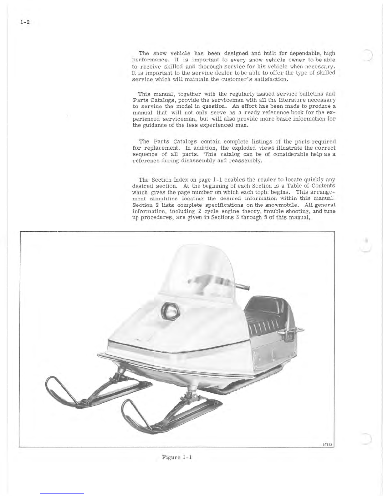
The
snow
vehicle
has
been
designed
and
built
for
dependable,
high
performance.
It
is
important
to
every
snow
vehicle
owner
to
be
able
to
receive
skilled
and
thorough
service
for
his
vehicle
when
necessary.
It
is
important
to
the
service
dealer
to
be
able
to
offer
the type of
skilled
service
which
will
maintain
the
customer's
satisfaction.
This
manual,
together
with
the
regularly
issued
service
bulletins
and
Parts
Catalogs,
provide
the
serviceman
with
all
the
literature
necessary
to
service
the
model
in
question.
An
effort
has
been
made
to
produce
a
manual
that
will
not
only
serve
as
a
ready
reference
book
for
the
ex
-
perienced
serviceman,
but
will
also
provide
more
basic
information
for
the
guidance
of
the
less
experienced
man.
The
Parts
Catalogs
contain
complete
listings
of
the
parts
required
for
replacement.
In
addition,
the
exploded
views
illustrate
the
correct
sequence
of
all
parts.
This
catalog
can
be of
considerable
help
as
a
reference
during
disassembly
and
reassembly.
The
Section
Index on page 1- 1
enables
the
reader
to
locate
quickly any
desired
section.
At
the
beginning
of
each
Section
is
a
Table
of
Contents
which
gives
the page
number
on which
each
topic
begins.
This
arrange-
ment
simplifies
locating
the
desired
information
within
this
manual.
Section
2
lists
complete
specifications
on
the
snowmobile.
All
general
information,
including
2
cycle
engine
theory,
trouble
shooting,
and
tune
up
procedures,
are
given
in
Sections
3
through
5 of
this
manual.
37323
Figure
1-1
)
-
(
Sections
6
through
11
provide
fully
illustrated,
detailed,
step-by-step
disassembly
and
reassembly
instructions
and
adjustment
procedures.
Section
12
provides
lubrication
and
storage
information.
In
this
way,
the
texts
treat
each
topic
separately;
theory
and
practice
are
not
intermixed.
This
makes
it
unnecessary
for
the
experienced
service-
man
to
reread
discussions
of
theory
along
with
specific
service
in-
formation.
Illustrations
placed
in
the
margins
provide
unimpeded
reading
of
explanatory
text,
and
permit
close
relationship
between
illustration
and
text.
Read
this
manual
carefully
to
become
thoroughly
familiar
with
the
procedures
described,
then
keep
it
readily
available
in
the
service
shop
for
use
as
a
reference.
If
properly
used,
it
will
enable
the
serviceman
to
give
better
service
to
the
snowmobile
owner,
and
thereby
build
and
maintain
a
reputation
for
reliable
service.
This
service
manual
covers
all
phases
of
servicing
the
snowmobile,
however,
new
service
situations
sometimes
arise.
If
a
service
question
does
not
appear
to
be
answered
in
this
manual,
you
are
invited
to
write
to
the
Service
Department
for
additional
help.
Always
be
sure
to
give
complete
information,
including
model
number
and
vehicle
identifica-
tion
number.
All
information,
illustrations,
and
specifications
contained
in
this
literature
are
based
on
the
product
information
available
at
the
time
of
publication.
The
right
is
reserved
to
make
changes
at
any
time
without
notice.
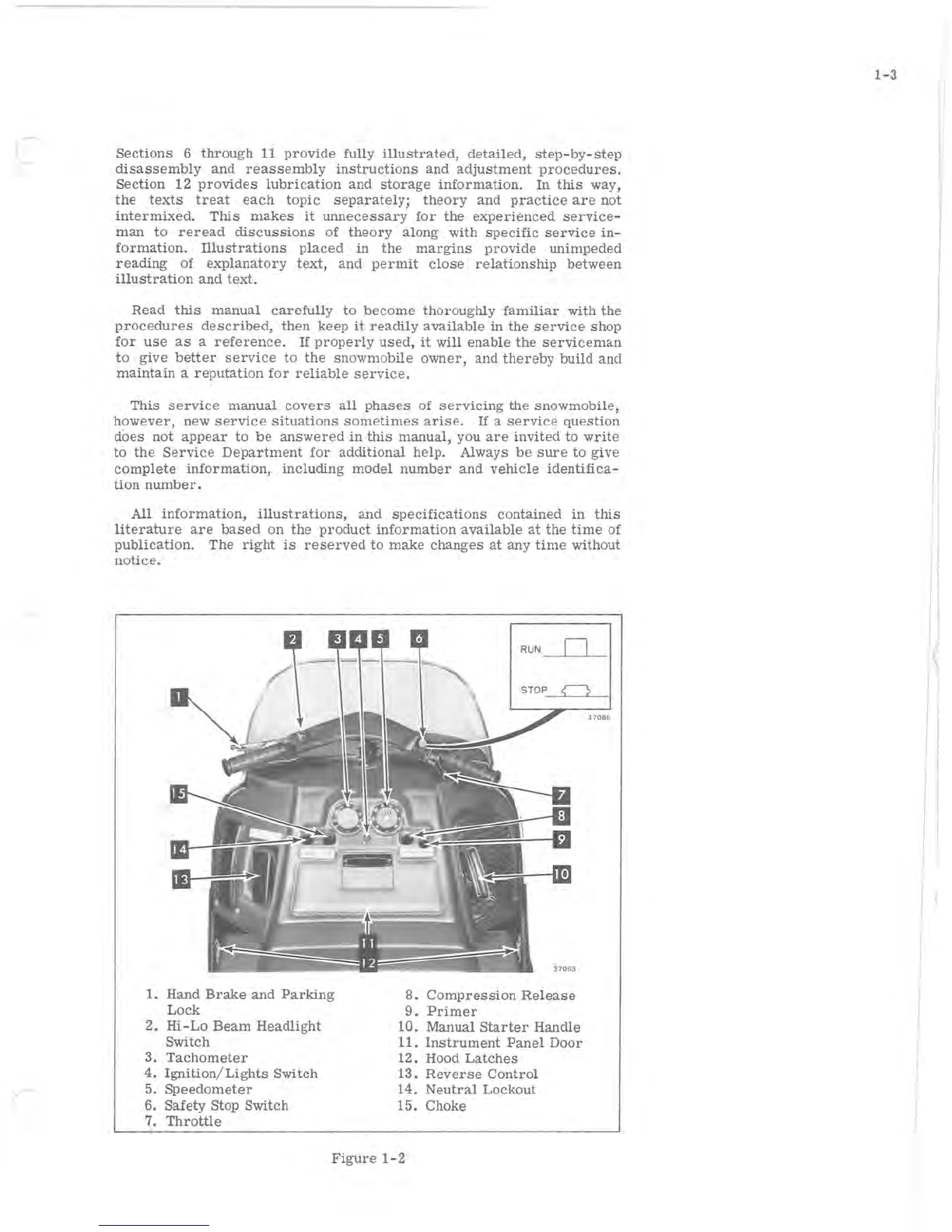
1.
Hand
Brake
and
Parking
Lock
2.
Hi-Lo
Beam
Headlight
Switch
3.
Tachometer
4.
Ignition
/
Lights
Switch
5.
Speedometer
6.
Safety
Stop Switch
7.
Throttle
8.
Compression
Release
9.
Primer
10. Manual
Starter
Handle
11.
Instrument
Panel
Door
12. Hood
Latches
13.
Reverse
Control
14.
Neutral
Lockout
15.
Choke
Figure
1-2
1-3

)
I
!
) \
I
j
I
j
:
I
J
j
2- 1
SECTION
2
SPECIFICATIONS
TABLE
OF
CONTENTS
SPECIFICATIONS.
• • • . • . . . . . . . • • • • .
2-2
TORQUE
SPECIFICATIONS
...•.••...•
2-3
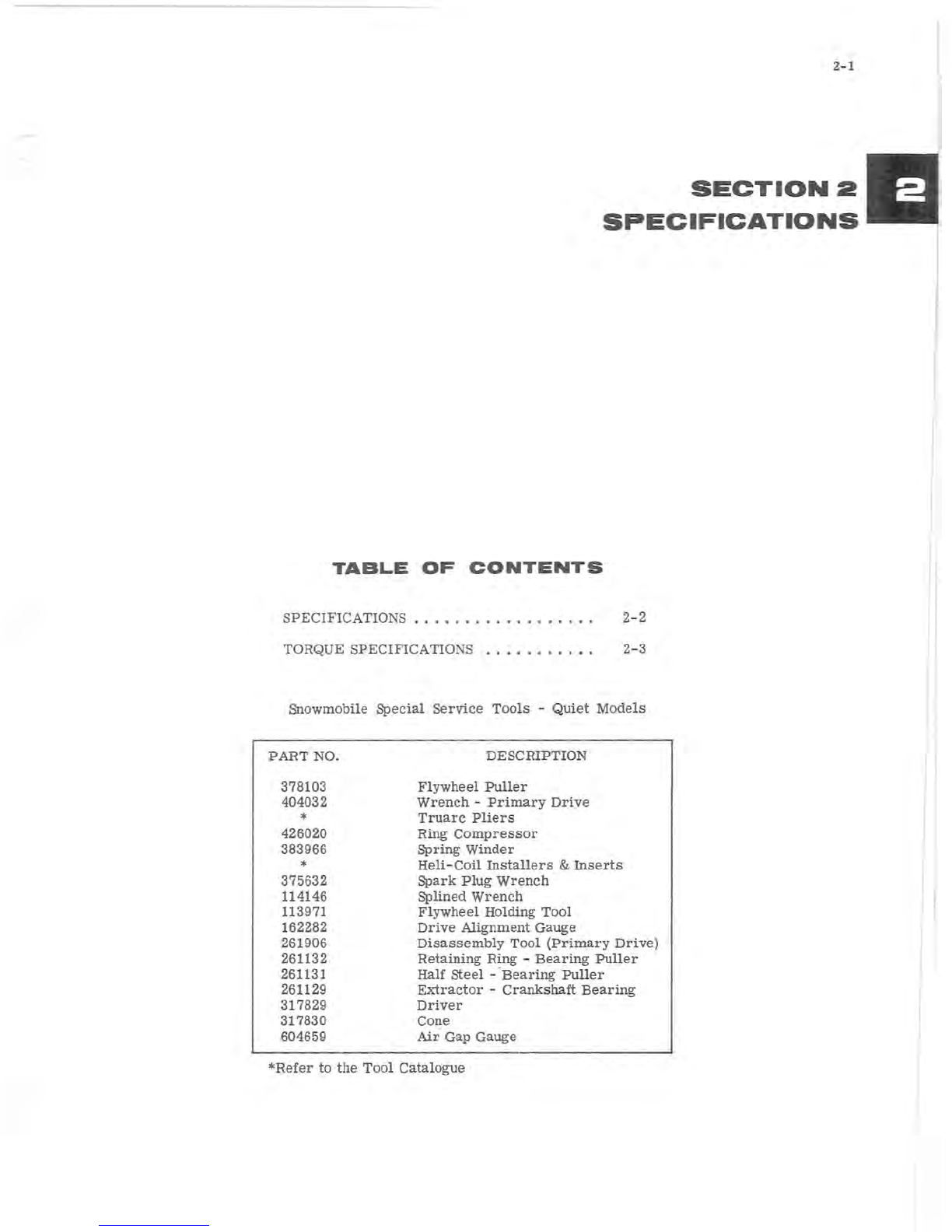
Snowmobile
Special
Service
Tools
-
Quiet
Models
PART
NO.
378103
404032
*
426020
383966
*
375632
114146
113971
162282
261906
261132
261131
261129
317829
317830
604659
DESCRIPTION
Flywheel
Puller
Wrench
-
Primary
Drive
Truarc
Pliers
Ring
Compressor
Spring
Winder
Heli-Coil
Installers
&
Inserts
Spark
Plug
Wrench
Splined
Wrench
Flywheel
Holding
Tool
Drive
Alignment
Gauge
Disassembly
Tool
(Primary
Drive)
Retaining
Ring -
Bearing
Puller
Half
steel
- '
Bearing
Puller
Extractor
-
Crankshaft
Bearing
Driver
Cone
Air
Gap
Gauge
*Refer
to
the
Tool
Catalogue

2-2
SPECIFICATION
S
oPROHIBITED: Snow
Vehicles
are
not
manufactured
for
highway
use
and
the
manufacturer
does
not
represent
that
they
are
equipped
with
all
the
devices
legally
required
for
such
use.
Length
Width
Height
....
· . . . . . . . . . . . . . . . . . . . . . . . . . . . . .
..
107
inches
• . . . . . . . . . . . . . . . . . . . . . . . . . . .
..
37
inches
· . . . . . . . . . . . . . . . . . .
..
44.9
inches
with
windshield
37
inches
without
windshield
Engine
.•.•....•...........••••••
OMC 2-
cycle
opposed
twin
Rating
......•••..••.•.••••.••••
Maximum
30 hp
at
5800
rpm
Starter
••.......•...................
Electric
and
manual
Variable
speed
drive
....•
Centrifugal
operated
sheave
engages
V-belt
Overall
ratio
••••.•••••.•....•••••••...•..•••
5.07
to
1
Final
drive
...•.•...•.••....•.........
ABA
35 double
chain
Sprocket
ratio
• . . . . . . . . . . • • . • . . . . • • • • • • . • . .
..
16
to
42
Reverse
transmission
..•.•..........
Dog
clutch
and
bevel
gears
Mufflers
............•.•...
Tuned
mufflers
for
quiet
operation
Brake
.•..........••...•••.•..•.•
Disc
type,
hand
operated
Throttle.
• . . • . • . . . • . . . . . . . . . • . . . . . • . . • . .
Thumb
operated
Track
..•.••..•.
Polyurethane
-
Specially
designed-fully
adjustable
Width
...•..•..•.•.....•••......••....•.
20.5
inches
Skis
...........
Formed
steel,
equipped with
shock-absorbing
leaf
springs
and
replaceable
wear
runners
Seating
capacity
..........•.....
Two
adults.
Vinyl
coated
cover,
molded
urethane
foam
cushion
Hood
.....................
Molded
fiberglass
Head
lamp
..........................
Sealed
beam
GE 4002
Tail
lamp
/
stop
lamp
............................
GE 1157
Fuel
tank.
. . . . . . .
..
Capacity
4.3
Imperial
gallons,
5.5 U.S.
gallons
Lubrication
......................
OMC
brand
50:1
lubricant
Carburetor
Needle
Adjustment
(Bendix
Float
Type
Carburetor)
High
speed
........
1-1
/ 4
turns
off
seat
minimum
Low
speed
.
..
1
to
1-1
/ 4
turns
off
seat
RPM
Ratings
Idle
.....
. . . . . . . . . . . . 1000 -1200
Transmission
belt
engaging
speed.
. . . . . . . .
..
Approx. 2500-2800
Maximum
RPM
at
which
neutral
control
will
operate
...
Approx. 2000
Ignition
Breakerless
magneto
C.D.
(Capacitor
Discharge)
ignition
Spark
plug
.....•..•..•.•••••••••..•.•.•
Champion
UJ2J
Spark
plug
gap . . • . . . . . . . • . • • • • • . . . • . •
..
.028 -.033
inch
Advance
sensor
coil
resistance
................•.
14-16
ohms
Retard
sensor
coil
resistance
............
27-29
ohms
Magneto
charge
coil
resistance
(2
coils)
total
of
....
875 ±
75
ohms
Ignition
coil
secondary
resistance
.............
1900 ± 190
ohms
Lighting
coil
resistance
..........•....
1.3
ohms
total
both
sides
Battery
•.
12
volt
Prestolite
Type
2920
or
equivalent
with
a
minimum
32
ampere
hour
rating,
and
with a
minimum
of 2.2
minutes
Engine
cold
starting
capacity
at
150
amperes
diSCharge, 0°
Fahren-
heit,
and a
5-second
voltage
reading
of 7.8
volts.
Dimensions
in
inches
are
approximately
7-3/4
long,
5-1/8
wide
and
7-1/4
high (to top of
terminals).
Weight
dry
17
lbs.,
wet
21.4
lbs.
Electrolyte
to
fill
0.44
U.S.
gallons.
Specific
gravity
1.265
Bore
and
stroke
• . . • • . . . • . . . . . . . . . .
..
2-3/4
x
2-1/4
inches
Piston
displacement
. . . • . • . • • • . • •
•.
26.7
cubic
inches
(437 cc)
Compression
ratio
........•......•••••.
. . • • •
••
6.8·
to
1
Cylinder
compression
• . . • . . . . . . . . . . . . . . • .
Minimum
105
PSI
Ring
diameter
......•.•.•..••••.•.•.•.....
2-
3/4
inches
Ring
thickness
. . . • • • • . • • . . . . . . • • • • • • • . . . • .
•.
1/16
inch
Clearances
Piston
-
wrist
pin.
. • . • • • • • . • • • • • • • • • • • • • . • .
.•
Press
fit
Piston
ring
gap
.•••..••••.......•.•••••••••.
.007-.017
Piston
ring
-
ring
groove.
• • • • . • • • • . . . • . • . . . • •
..
.002-.004
Cylinder
-
piston
.•••••.••.•
Top of
piston
to
cylinder
.012
-.015
Bottom
of
piston
to
cylinder
.006
-.008
SpeCifications
and
features
may
be
changed
at
any
time
without
notice
and
without
obligation
towards
vehicles
previously
manufactured.
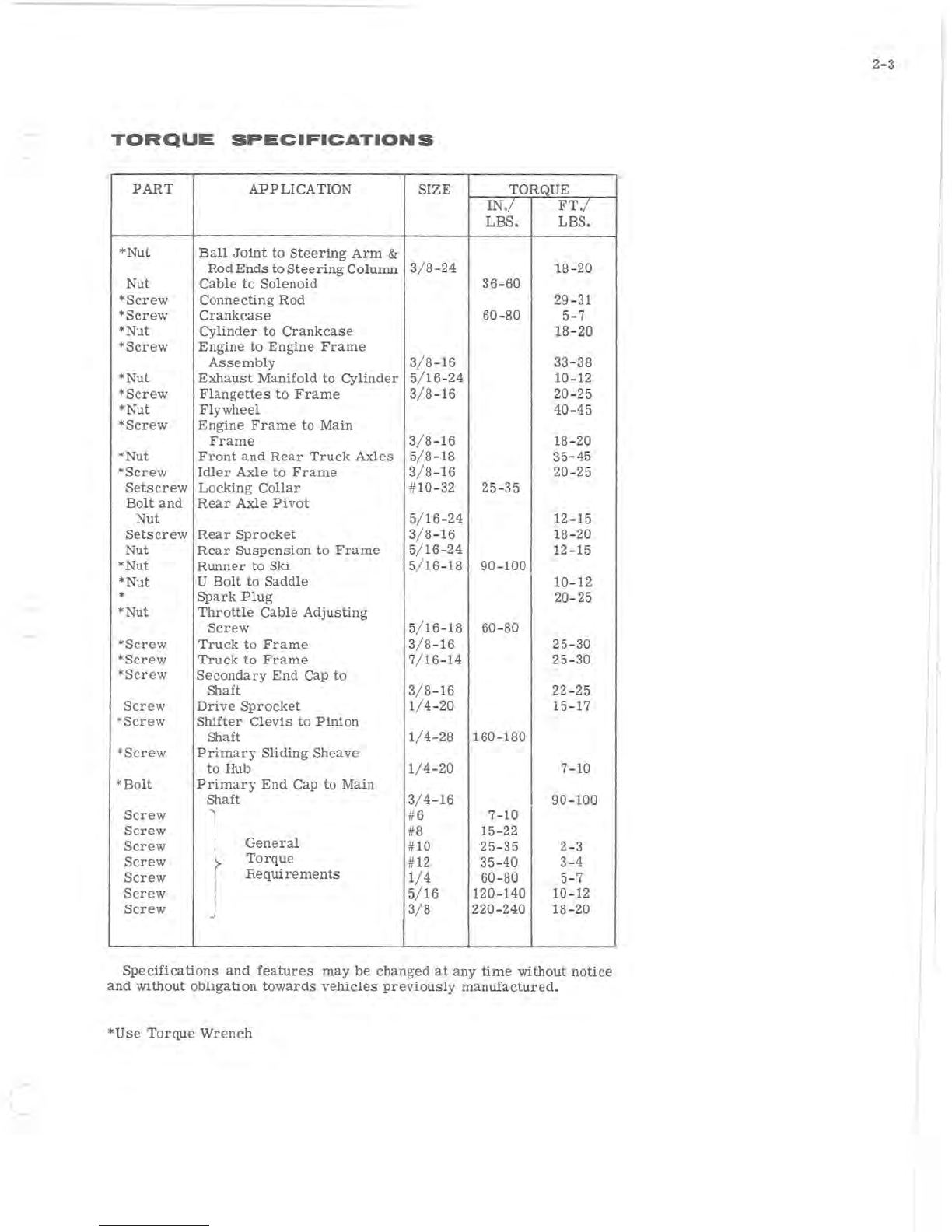
TORQUE
SPECIFICATIONS
PART
APPLICATION
SIZE
TORQUE
IN.
/
FT.
/
LBS. LBS.
*Nut
Ball
Joint
to
Steering
Arm
&
Rod
Ends
to
Steering
Column
3/ 8-24
18
-
20
Nut
Cable
to
Solenoid
36-
60
*Screw
Connecting
Rod
29
-
31
*Screw
Crankcase
60
-
80
5-7
*Nut
cYlinder
to
Crankcase
18
-20
*Screw
Engine
to
Engine
Frame
Assembly
3/ 8-
16
33
-38
*Nut
Exhaust
Manifold
to
Cylinder
5/
16
-
24
10
-
12
*Screw
Flangettes
to
Frame
3/ 8-16 20-25
*Nut
Flywheel
40-45
*Screw
Engine
Frame
to
Main
Frame
3/ 8-16
18
-
20
*
Nut
Front
and
Rear
Truck
Axles
5/ 8-
18
35-
45
*Screw
Idler
Axle
to
Frame
3/ 8-
16
20
-
25
Setscrew
Locking
Collar
#10-
32
25
-
35
Bolt
and
Rear
Axle
Pivot
Nut
5/
16
-
24
12
-
15
Setscrew
Rear
Sprocket
3/ 8-16
18
-20
Nut
Rear
Suspension
to
Frame
5/
16
-
24
1 90-100 I
12
-
15
*Nut
Runner
to
Ski
5/ 16-
18
*
Nut
U
Bolt
to
Saddle
10-
12
*
Spark
Plug
20
-
25
*
Nut
Throttle
Cable
Adjusting
Screw
5/ 16-18
60
-
80
*Screw
Truck
to
Frame
3/ 8-16
25
-
30
*Screw
Truck
to
Frame
7/ 16-14
25
-
30
*Screw
Secondary
End
Cap
to
Shaft
3/ 8-16 2
2-
25
Screw
Drive
Sprocket
1/ 4-20
15
-
17
*Screw
Shifter
Clevis
to
Pinion
Shaft
1/ 4-
28
160-180
*
Screw
Primary
Sliding
Sheave
to
Hub 1/ 4-20 7-10
*Bolt
Primary
End
Cap
to
Main
Shaft
3/ 4-
16
I
90
-100
Screw
#6 7-10
Screw
#8
15
-
22
Screw
General
#
10
25
-
35
2-3
Screw
7
Torque
#12
35
-40 3-4
Screw
ReqUirements
1/ 4 60-80 5-7
Screw
5/ 16 120-140
10
-
12
Screw
3/ 8 220-240
18
-
20
Specifications
and
features
may
be
changed
at
any
time
without
notice
and
without
obligation
towards
vehicles
previously
manufactured.
*Use
Torque
Wrench
2-3

-.
J
3-1
SECTION
3
GENERAL
SNOWMOBILE
INFORMATION
TABLE
OF
CONTENTS
TWO-CYCLE
ENGINE
OPERATION
. . • • •
•.
3-2
COMPRESSION.
. . . . . . . . • • • • • • • • • •
••
3-2
CARBURETION
• • . . • • . . . • • • • . . • . • • • •
3-3
IGNITION.
. • . . • . . . . • • • . • • • • . . • • .
.•
3-4
LIGHTING
SYSTEM
• . . . . . • . • • . • . • . •
•.
3-4
POWER
FLOW.
• • • • • • • • • • • • • • . • . •
•.
3-5
PRIMARY
DRIVE.
. . • • • • • • • . • • . • • • •
3-5
NEUTRAL
CONTROL.
• . . . . • • • . • • •
•.
3-6
SECONDARY
DRIVE.
. . . • . • • • . • • . •
..
3-6
REVERSE
TRANSMISSION. . • . . . . . • •
•.
3-6
II
3-2
POWER
STROKE
-
DOWN
COMBUSTION
OF
FUEL-AIR
ROD
COUNTER-
BALANCE
AXIS
OF
ROTATION
Figure
3-1
17133
FUEL
INTAKE
AND
EXHAUST
LEAF
VALVES
EXHAUST
PORT
OPEN
Figure
3-2
17
134
COMPRESSION
STROKE
-
UP
EXHAUST
PORT
CLOSED
Figure
3-3
17135
TWO
CYCLE
ENGINE
THEORY
An
internal
combustion
engine
is
one
in
which
fuel
is
burned
inside
the
engine:
a
charge
of
fuel
is
introduced
into
a
combustion
chamber
(cylinder)
within
the
engine
and
ignited.
The
energy
released
by
the
expansion
of
the
burning
fuel
is
converted
to
torque
by
the
piston,
con-
necting
rod,
and
crankshaft.
Internal
combustion
engines
are
classified
as
either
four-cycle
or
two-cycle
engines
.
The
"four"
and the
"two"
refers
to
the
number
of
piston
strokes
required
to
complete
a
power
cycle
of
intake,
compres-
sion,
power,
and
exhaust.
A
piston
stroke
is
piston
travel
in
one
direc-
tion
only; up
is
one
stroke,
down
is
another.
In
a
four-cycle
engine,
two
crankshaft
revolutions,
or
four
strokes,
are
required
for
each
power
cycle.
In a
two-cycle
engine
only one
crankshaft
revolution
is
required
per
power
cycle.
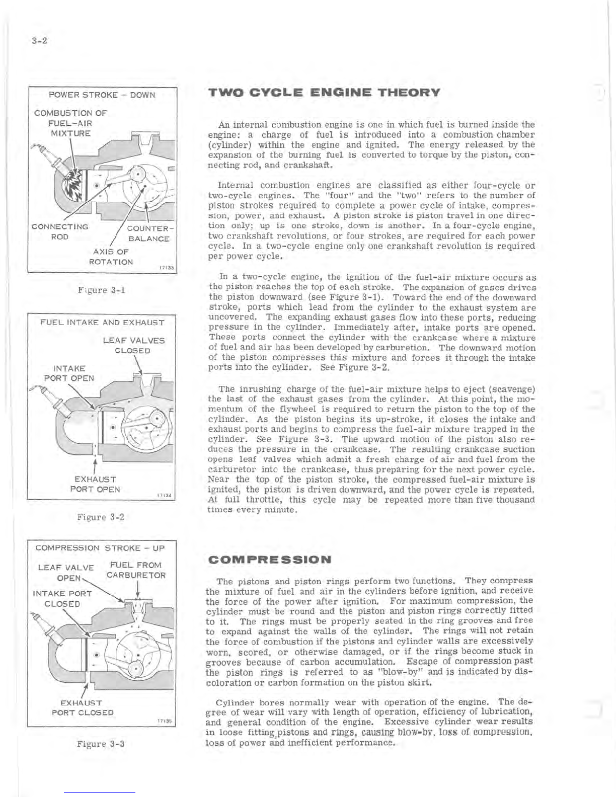
In
a
two-cycle
engine,
the
ignition
of
the
fuel-air
mixture
occurs
as
the
piston
reaches
the
top
of
each
stroke.
The
expansion
of
gases
drives
the
piston
downward
(see
Figure
3-1).
Toward
the
end
of
the
downward
stroke,
ports
which
lead
from
the
cylinder
to
the
exhaust
system
are
uncovered.
The
expanding
exhaust
gases
flow
into
these
ports,
reducing
pressure
in
the
cylinder.
Immediately
after,
intake
ports
are
opened.
These
ports
connect
the
cylinder
with
the
crankcase
where
a
mixture
of
fuel
and
air
has
been
developed
by
carburetion.
The
downward
motion
of
the
piston
compresses
this
mixture
and
forces
it
through
the
intake
ports
into
the
cylinder.
See
Figure
3-2.
The
inrushing
charge
of
the
fuel-air
mixture
helps
to
eject
(scavenge)
the
last
of
the
exhaust
gases
from
the
cylinder.
At
this
point,
the
mo-
mentum
of
the
flywheel
is
required
to
return
the
piston
to
the
top of
the
cylinder.
As
the
piston
begins
its
up-stroke,
it
closes
the
intake
and
exhaust
ports
and
begins
to
compress
the
fuel-air
mixture
trapped
in the
cylinder.
See
Figure
3-3.
The
upward
motion
of
the
piston
also
re-
duces
the
pressure
in
the
crankcase.
The
resulting
crankcase
suction
opens
leaf
valves
which
admit
a
fresh
charge
of
air
and
fuel
from
the
carburetor
into
the
crankcase,
thus
preparing
for
the
next
power
cycle.
Near
the
top of
the
piston
stroke,
the
compressed
fuel-air
mixture
is
ignited,
the
piston
is
driven
downward,
and
the
power
cycle
is
repeated.
At full
throttle,
this
cycle
may
be
repeated
more
than
five
thousand
times
every
minute.
COMPRESSION
The
pistons
and
piston
rings
perform
two
functions.
They
compress
the
mixture
of
fuel
and
air
in
the
cylinders
before
ignition,
and
receive
the
force
of
the
power
after
ignition.
For
maximum
compression,
the
cylinder
must
be
round
and
the
piston
and
piston
rings
correctly
fitted
to
it.
The
rings
must
be
properly
seated
in
the
ring
grooves
and
free
to
expand
against
the
walls
of
the
cylinder.
The
rings
will
not
retain
the
force
of
combustion
if
the
pistons
and
cylinder
walls
are
excessively
worn,
scored,
or
otherwise
damaged,
or
if
the
rings
become
stuck
in
grooves
because
of
carbon
accumulation.
Escape
of
compression
past
the
piston
rings
is
referred
to
as
"blow-by"
and
is
indicated
by
dis-
coloration
or
carbon
formation
on
the
piston
skirt.
Cylinder
bores
normally
wear
with
operation
of
the
engine.
The
de-
gree
of
wear
will
vary
with
length
of
operation,
efficiency
of
lubrication,
and
general
condition
of
the
engine.
Excessive
cylinder
wear
results
in
loose
fitting,
pistons
and
rings,
causing
blow-by,
loss
of
comprgggion,
loss
of
power
and
inefficient
performance.
r
Piston
rings
are
formed
in
such
a
manner
that
when
installed
on
the
piston,
they
bear
against
the
cylinder
wall
with a
light,
even
pressure.
Excessive
ring
pressure
against
cylinder
wall
increases
friction,
caus-
ing
high
operating
temperature,
sluggish
performance,
and
abnormal
wear
or
scoring.
Insufficient
pressure
allows
blow-by,
which
reduces
power,
and
causes
overheating
and
carbon
formation·
on
piston
skirt.
Compression
leakage
may
also
occur
at
spark
plugs.
A
cracked
spark
plug
insulator
will
cause
similar
trouble.
Although
compression
is
pri-
marily
dependent
on
the
piston,
rings,
and
cylinder,
these
other
sources
of
leakage
should
be
investigated
when
compression
loss
is
noted.
Since
the
ring
tends
to
flex
as
it
fOllows
the
cylinder
contour
during
engine
operation,
clearance
or
gap
must
be
provided
between
the
ring
ends
to
prevent
butting.
The
ring
gap
also
allows
the
ring
to
expand
(elongate)
as
engine
temperature
rises
during
operation.
Insufficient
gap
clearance
will
cause
the
ring
to
bend
or
warp
as
it
flexes
and
ex-
pands;
excessive
gap
clearance
will
permit
loss
of
compression.
Compression
leakage
will
occur
if
the
compression
relief
valve
link-
age
is
adjusted
with
insufficient
clearance
on
the
cable
ends.
The
relief
valves
vent
combustion
chamber
pressure
through
a
by-pass
port.
Compression
may
also
be
affected
by
the
fuel
induction
and
exhaust
systems.
Since
the
fuel
vapor
is
first
compressed
in
the
crankcase,
leakage
here
will
affect
engine
performance.
Possible
trouble
spots
include
leaf
valve
assemblies,
seals
between
crankcase
halves,
and
crankshaft
bearing
seals
.
Exhaust
ports
which
have
become
clogged
because
of
excessive
deposits
of
carbon
will
hinder
the
efficient
transfer
of
exhaust
gases.
Excessive
carbon
build-up
on
piston
heads
or
elsewhere
in
the
cylin-
der
walls
can
result
in
a
loss
of
power.
Following
the
trouble
shooting
procedures
in
Section
4 and
the
recom-
mended
tune-up
procedures
given
in
Section
5 will
assure
that
all
areas
affecting
fuel
induction,
compression,
and
exhaust
will
be
considered
as
part
of
every
trouble
shooting
procedure.
An
engine
with low
or
uneven
compression
cannot
be
successfully
tuned
for
peak
performance.
It
is
essential
that
improper
compression
be
corrected
before
proceeding
with
an
engine
tune-up.
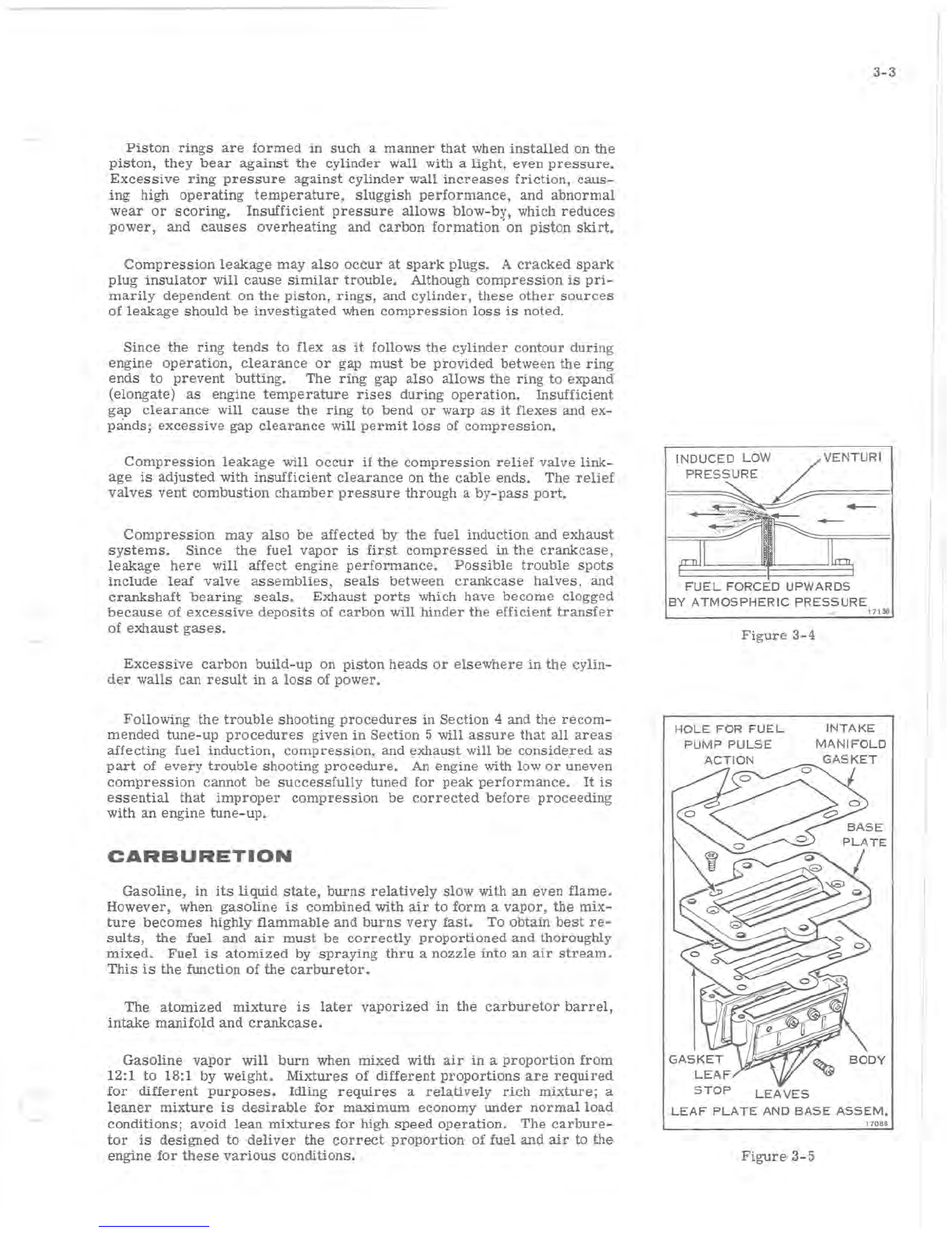
CARBURETION
Gasoline,
in
its
liquid
state,
burns
relatively
slow
with
an
even
flame.
However,
when gaSOline
is
combined
with
air
to
form
a
vapor,
the
mix-
ture
becomes
highly
flammable
and
burns
very
fast.
To
obtain
best
re-
sults,
the
fuel
and
air
must
be
correctly
proportioned
and
thoroughly
mixed.
Fuel
is
atomized
by
spraying
thru
a
nozzle
into
an
air
stream.
This
is
the
function
of
the
carburetor.
The
atomized
mixture
is
later
vaporized
in
the
carburetor
barrel,
intake
manifo~d
and
crankcase.
GaSOline
vapor
will
burn
when
mixed
with
air
in
a
proportion
from
12:1
to
18:1 by
weight.
Mixtures
of
different
proportions
are
required
for
different
purposes.
Idling
requires
a
relatively
rich
mixture;
a
leaner
mixture
is
desirable
for
maximum
economy
under
normal
load
conditions;
avoid
lean
mixtures
for
high
speed
operation.
The
carbure-
tor
is
designed
to
deliver
the
correct
proportion
of
fuel
and
air
to
the
engine
for
these
various
conditions.
3-3
INDUCED
LOW
/
VENTURI
PRESSURE
~
~
FUEL
FORCED
UPWARDS
BY
ATMOSPHERIC
PRESSURE
Figure
3-4
HOLE
FOR
FUEL
PUMP
PULSE
LEAVES
17
1
36
INTAKE
MANIFOLD
LEAF
PLATE
AND
BASE
ASSEM.
17
0
88
Figure
3-5
3-4
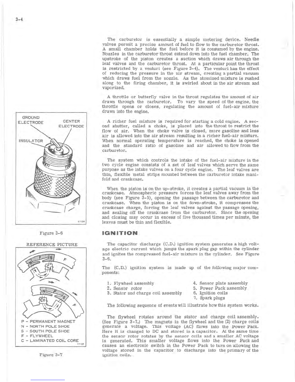
GROUND
ELECTRODE
CENTER
Figure
3-6
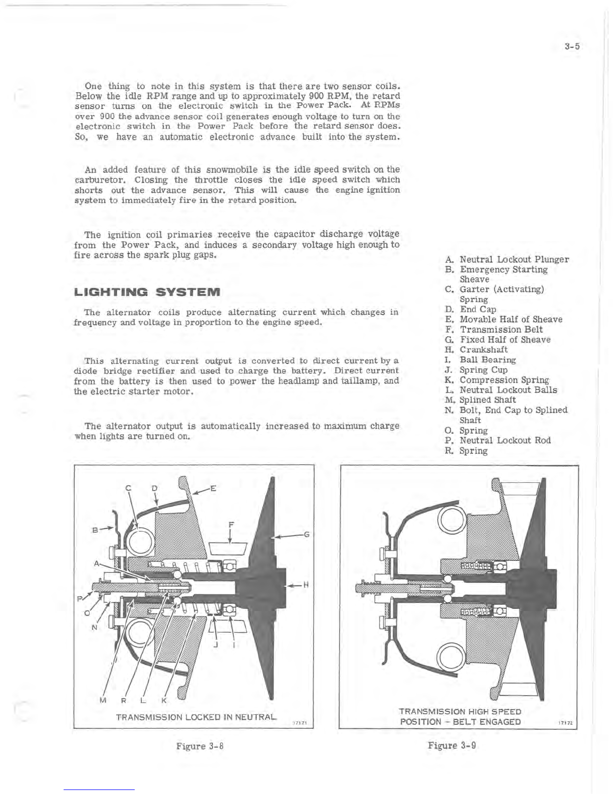
REFERENCE
PICTURE
P -
PERMANENT
MAGNET
N -
NORTH
POLE
SHOE
S -
SOUTH
POLE
SHOE
F -
FLYWHEEL
1713
8
C -
LAMINATED
COIL
CORE
17137
Figure
3-7
The
carburetor
is
essentially
a
simple
metering
device.
Needle
valves
permit
a
precise
amount
of
fuel
to
flow
to
the
carburetor
throat.
A
small
chamber
holds
the
fuel
before
it
is
consumed
by
the
engine.
Nozzles
in
the
carburetor
throat
extend
down
into
the
fuel
chamber.
The
upstroke
of
the
piston
creates
a
suction
which
draws
air
through
the
leaf
valves
and
the
carburetor
throat.
At a
particular
point
the
throat
is
restricted
by
a
venturi
(see
Figure
3-4).
The
venturi
has
the
effect
of
reducing
the
pressure
in
the
air
stream,
creating
a
partial
vacuum
which
draws
fuel
from
the
nozzle.
As
the
atomized
mixture
is
rushed
along
to
the
firing
chamber,
it
is
swirled
about
in
the
air
stream
and
vaporized.
A
throttle
or
butterfly
valve
in
the
throat
regulates
the
amount
of
air
drawn
through
the
carburetor.
To
vary
the
speed
of
the
engine,
the
throttle
opens
or
closes,
regulating
the
amount
of
fuel-air
mixture
drawn
into
the
engine.
A
richer
fuel
mixture
is
required
for
starting
a
cold
engine. A
sec-
ond
shutter,
called
a choke,
is
placed
into
the
throat
to
restrict
the
flow of
air.
When
the
choke
valve
is
closed,
more
gasoline
and
less
air
is
allowed
into
the
air
stream
resulting
in
a
richer
fuel-air
mixture.
When
normal
operating
temperature
is
reached,
the
choke
is
opened
and
the
standard
ratio
of gasOline and
air
allowed
to
flow
from
the
carburetor.
The
system
which
controls
the
intake
of
the
fuel-air
mixture
in
the
two
cycle
engine
consists
of a
set
of
leaf
valves
which
serve
the
same
purpose
as
the
intake
valves
on a
four
cycle
engine.
The
leaf
valves
are
thin,
flexible
metal
strips
mounted
between
the
carburetor
intake
mani-
fold and
crankcase.
When
the
piston
is
on
the
up-stroke,
it
creates
a
partial
vacuum
in
the
crankcase.
Atmospheric
pressure
forces
the
leaf
valves
away
from
the
body
(see
Figure
3-5),
opening
the
passage
between
the
carburetor
and
crankcase.
When
the
piston
is
on
the
down-stroke,
it
compresses
the
crankcase
Charge, forCing
the
leaf
valves
against
the
passage
opening,
and
sealing
off
the
crankcase
from
the
carburetor.
Since
the
opening
and
closing
may
occur
in
excess
of five
thousand
times
per
minute,
the
leaves
must
be
thin
and
flexible.
IGNITION
The
capacitor
discharge
(C.D.)
ignition
system
generates
a high
volt-
age
electriC
current
which
jumps
the
spark
plug
gap within
the
cylinder
and
ignites
the
compressed
fuel-air
mixture
in
the
cylinder.
See
Figure
3-6.
The
(C.D.)
ignition
system
is
made
up of
the
following
major
com-
ponents:
1.
Flywheel
assembly
4.
Sensor
plate
assembly
2.
Sensor
rotor
5.
Power
Pack
assembly
3.
Stator
and
charge
coil
assembly
6. Ignition
coils
7.
Spark
plugs
The following
sequence
of
events
will
illustrate
how
this
system
works.
The flywheel
rotates
around
the
stator
and
charge
coil
assembly.
(See
Figure
3-7.)
The
magnets
in
the
flywheel
and
the
(2)
charge
coils
generate
a
voltage.
This
voltage
(AC) flows
into
the
Power
Pack.
Here
it
is
changed
to
DC
and
stored
in
a
capacitor.
At
the
same
time
the
sensor
rotor
rotates
by
the
sensor
coils
and
a
smaller
AC
voltage
is
generated.
This
smaller
voltage
flows
into
the
Power
Pack
and
causes
an
electronic
switch
in
the
Power
Pack
to
turn
on allowing
the
voltage
stored
in
the
capaCitor
to
discharge
into
the
primary
of
the
ignition
coils.
c
One
thing
to
note
in
this
system
is
that
there
are
two
sensor
coils.
Below
the
idle
RPM
range
and up
to
approximately
900
RPM.
the
retard
sensor
turns
on
the
electronic
switch
in
the
Power
Pack.
At
RPMs
over
900
the
advance
sensor
coil
generates
enough
voltage
to
turn
on the
electronic
switch
in
the
Power
Pack
before
the
retard
sensor
does.
So, we
have
an
automatic
electronic
advance
built
into
the
system.
An
added
feature
of
this
snowmobile
is
the
idle
speed
switch
on
the
carburetor.
Closing
the
throttle
closes
the
idle
speed
switch
which
shorts
out
the
advance
sensor.
This
will
cause
the
engine
ignition
system
to
immediately
fire
in
the
retard
position.
The
ignition
coil
primaries
receive
the
capacitor
discharge
vO,ltage
from
the
Power
Pack,
and
induces
a
secondary
voltage
high enough
to
fire
across
the
spark
plug
gaps.
LIGHTING
SYSTEM
The
alternator
coils
produce
alternating
current
which
changes
in
frequency
and
voltage
in
proportion
to
the
engine
speed.
This
alternating
current
output
is
converted
to
direct
current
by a
diode
bridge
rectifier
and
used
to
charge
the
battery.
Direct
current
from
the
battery
is
then
used
to
power
the
headlamp
and
taillamp,
and
the
electric
starter
motor.
The
alternator
output
is
automatically
increased
to
maximum
charge
when
lights
are
turned
on.
3-5
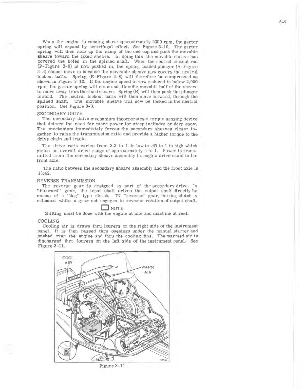
A.
Neutral
Lockout
Plunger
B.
Emergency
Starting
Sheave
C.
Garter
(Activating)
Spring
D.
End
Cap
E. Movable Half of
Sheave
F.
Transmission
Belt
G.
Fixed
Half of
Sheave
H.
Crankshaft
I.
Ball
Bearing
J.
Spring
Cup
K.
Compression
Spring
L.
Neutral
Lockout
Balls
M.
Splined
Shaft
N.
Bolt,
End Cap
to
Splined
Shaft
O.
Spring
P.
Neutral
Lockout Rod
R.
Spring
TRANSMISSION
LOCKED
IN
NEUTRAL
17171
TRANSMISSION
HIGH
SPEED
POSITION
-
BELT
ENGAGED
17172
Figure
3-8
Figure
3-9

3-6
POWER
FLOW
The
transmission
assembly
transmits
power
from
the
engine
to
the
front
axle
which
propels
the
vehicle
along
the
track.
The
primary
sheave
assembly
is
attached
directly
to
the
crankshaft.
The
secondary
sheave
assembly
has
its
own mounting
pedestal
and
is
larger
in
diam-
eter
than
the
primary
sheave
assembly.
The
two
are
connected
by a
transmission
belt.
PRIMARY
DRIVE
The
primary
sheave
is
centrifugally
operated
and
engages
the
trans-
mission
belt
when
the
engine
speed
reaches
2500 to 2800
rpm.
When
the
engine
is
rotating
at
idle
speed
or
below 2500 to 2800
rpm,
the
trans-
mission
belt
rides
on a
ball
bearing
between
the
halves
of
the
primary
sheave
assembly
(see
Figure
3-8).
The
primary
sheave
assembly
halves
are
separated
by
a
compression
spring
in
the
hub of
the
movable
sheave
half.
As
the
engine
speed
increases,
centrifugal
effect
forces
a
garter
spring
in
the
end cap
outward
against
the
contour
of
the
end
cap
and
axially
against
the
movable
sheave
half. As
the
sheaves
are
brought
together,
the
transmission
belt
is
forced
outward
to
ride
on a
larger
diameter
of
the
primary
sheave
assembly,
increasing
belt
speed
(see
Figure
3-9).
Since
the
belt
length
remains
constant,
the
secondary
sheave
halves
spread
,
apart,
allowing
the
belt
to
ride
on a
smaller
diam-
eter.
In
this
way,
the
engine
transmits
power
through
a
variable
ratio,
presenting
the
engine with a
mechanical
advantage
most
favorable
for
the
speed
at
which
it
is
operating.
NEUTRAL
CONTROL
A
neutral
control
mechanism
is
used
to
prevent
the
drive
from
engag-
ing
during
starting,
warm-up
period,
and
idle.
When
the
neutral
lockout
plunger
is
actuated,
a cone on
the
end
of
the
plunger
raises
two
balls
through
the
splines
of
the
primary
sheave
assembly
and
into
the
path
of
the
movable
sheave
half,
preventing
it
from
engaging
the
belt.
The
neutral
control
is
spring
actuated
and will
engage
only when
the
engine
is
below
approximately
2000
rpm.
TIONING
BECAUSE
RPM
TOO
HIGH
17275
Figure
3-10
r
When
the
engine
is
running
above
approximately
2000
rpm,
the
garter
spring
will
expand
by
centrifugal
effect.
See
Figure
3-10.
The
garter
spring
will
then
ride
up
the
ramp
of
the
end
cap
and
push
the
movable
sheave
toward
the
fixed
sheave.
In
doing
this,
the
movable
sheave
has
covered
the
holes
in
the
splined
shaft.
When
the
neutral
lockout
rod
(P-Figure
3-8)
is
now
pushed
in,
the
spring
loaded
plunger
(A-Figure
3-8)
cannot
move
in
because
the
moveable
sheave
now
covers
the
neutral
lockout
balls.
Spring
(R-Figure
3-8)
will
therefore
be
compressed
as
shown
in
Figure
3-10.
If
the
engine
speed
is
now
reduced
to
below
2,000
rpm,
the
garter
spring
will
close
and
allow
the
movable
half
of
the
sheave
to
move
away
from
the
fixed
sheave.
Spring
(R)
will
then
push
the
plunger
inward.
The
neutral
lockout
balls
will
then
move
outward,
through
the
splined
shaft.
The
movable
sheave
will
now
be
locked
in
the
neutral
pOSition.
See
Figure
3-8.
SECONDARY DRIVE
The
secondary
drive
mechanism
incorporates
a
torque
sensing
device
that
detects
the
need
for
more
power
for
steep
inclindes
or
deep
snow.
The
mechanism
immediately
forces
the
secondary
sheaves
closer
to-
gether
to
raise
the
transmission
ratio
and
provide
a
higher
torque
to
the
drive
chain
and
track.
The
drive
ratio
varies
from
3.3
to
1
in
low
to
.67
to
1
in
high which
yields
an
overall
drive
range
of
approximately
5
to
1.
Power
is
trans-
mitted
from
the
secondary
sheave
assembly
through
a
drive
chain
to
the
front
axle.
The
ratio
between
the
secondary
sheave
assembly
and
the
front
axle
is
16:42.
REVERSE TRANSMISSION
The
reverse
gear
is
designed
as
part
of
the
secondary
drive.
In
"Forward"
gear,
the
input
shaft
drives
the
output
shaft
directly
by
means
of a
"dog"
type
clutch.
IN
"reverse"
gear,
the
dog
clutch
is
released
while a
gear
set
engages
to
reverse
rotation
of
output
shaft.
o NOTE
Shifting
must
be
done with
the
engine
at
idle
and
machine
at
rest.
COOLING
Cooling
air
is
drawn
thru
louvers
on
the
right
side
of
the
instrument
panel.
It
is
then
passed
thru
openings
under
the
manual
starter
and
pushed
over
the
engine
and
thru
the
COOling
fins.
The
warmed
air
is
discharged
thru
louvers
on
the
left
side
of
the
instrument
panel.
See
Figure
3-11.
Figure
3-11
3-7

)
(
4-1
SECTION
4
TROUBLE
SHOOTING
TABLE
OF
CONTENTS
DESCRIPTION.
• • • • . . • • . . • . • . • • . . .
..
4-
2
TROUBLE
SHOOTING
PROCEDURES.
• • •
••
4-3
STARTING.
. • . . . . . . . • • • • • . . • • •
••
4-3
STARTING
-MANUAL
STARTER.
• . • •
.•
4-4
STARTING
-
ELECTRIC
STARTER.
. • .
•.
4-4
RUNNING -LOW
SPEED
ONLY
. . . • . •
••
4-4
RUNNING -HIGH
SPEED
ONLY.
• . . • .
•.
4-4
RUNNING -HIGH AND LOW
SPEED.
• .
•.
4-5
4-2
DESCRIPTION
This
section
provides
trouble
shooting
procedures
for
the
snow
ma
-
chine.
Steps
to
be
followed
in
determining
causes
of
unsatisfactory
per-
formance
are
outlined.
Being
able
to
locate
the
cause
of
trouble
in
an
improperly
operating
snow
machine
is
as
important
as
being
able
to
correct
the
trouble.
A
systematic
approach
to
trouble
shooting
is
important
if
the
trouble
is
to
be
located
and
identified
in
minimum
time.
Any
service
operation
can
be
broken
down into
three
steps:
1.
Identifying
the
problem
2.
Determining
the
cause
of
the
problem,
and
3.
Correcting
the
problem
.
Familiarity
with
the
factors
which
affect
two-cycle
engine
perform-
ance
is
important
in
making
a
correct
service
diagno
s
is
.
Factors
which
affect
engine
performance
include
the
quality
of
the
fuel
and
fuel
mixtures,
compression,
ignition,
and
proper
drive
system
adjustment.
Engine
theory,
compression,
carburetion,
ignition
and
power
flow
are
discussed
in
Section
3.
Correct
fuel
mixture
for
this
snowmobile
is
outlined
on
the
inside
front
cover,
and
fuel
blending
is
discussed
in
Sec-
tion
12.
Familiarity
with
factors
which
contribute
to
abnormal
per
-
formance
of an
engine
are
similarly
helpful.
The
skilled
mechanic's
experience
is
a
great
asset
here.
J
r
TROUBLE
SHOOTING
PROCEDURES
Trouble
Shooting
to
determine
the
caus~
of any
operating problem may
be
broken
down
into
the
fol-
lowing
steps:
a.
Obtaining
an
accurate
description
of
the
trouble.
b.
Preliminary
inspection.
c.
Use
of
Trouble
Check
Chart
to
analyze
engine
performance.
An
accurate
description
of
the
trouble
is
essential
for
trouble
shooting.
The
owner's
comments
may
provide
valuable
information
which
will
serve
as
a
clue
to
the
cause
of
the
problem.
A
preliminary
inspection
should
include
the
follow-
ing
checks.
a.
Correct
spark
plugs
b.
Throttle
linkage
properly
adjusted
c.
Tank
filled
with
fresh,
clean
fuel of
the
proper
mixture
d.
Spark
at
each
spark
plug
e.
Carburetor
adjusted
correctly
f.
Compression.
Turn
flywheel
by
hand
or
with
recoil
starter.
If
compression
is
present,
it
can
be
felt
when
turning
through
one
complete
revolution
of
the
flywheel.
If
little
or
no
com-
pression
exists
in
both
cylinders,
engine
will
spin
very
easily.
STARTING
1.
Hard
to
start
or
won't
start
a.
Empty
gas
tank
b.
Incorrect
gas-lubricant
ratio
c. Old
fuel,
or
water
or
dirt
in
fuel
system
d.
Fuel
line
improperly
connected
e.
Fuel
line
kinked
or
severely
pinched
f.
Engine
not
primed
g.
Clogged
fuel
line
or
fuel
filter
h.
Clogged
check
valve
i.
Carburetor
adjustments
too
lean
j. Low
speed
needle
bent
or
bowed
k.
Engine
flooded
4-3
1.
Leaf
valves
not
functioning
properly
mo
Faulty
gaskets
n.
Spark
plugs
fouled,
improperly
gapped,
dirty
or
broken
o.
Loose
or
broken
wire
or
frayed
insulation
in
ignition
system
wiring
p.
Sheared
sensor
hub
key
q.
Faulty
coils
r. Key
switch,
connector
or
grounded
switch
wire
s.
Binding
in
engine
t.
Faulty
sensor,
charge
COils,
Power
Pack
or
connecting
wiring.
2.
Engine
won't
turn
over
a.
Cylinder
wall
corrosion,
seized
piston
or
bearing
b.
Engine
improperly
assembled
after
repair
3.
Cranks
over
extremely
easily
a.
Spark
plug(s)
loose
b.
Cylinder
or
pistons
scored
c.
Rings
worn
or
carboned
d.
Faulty
crankcase
gasket
or
crankseal(s)
e.
Broken
or
damaged
leaf
valves
4.
Won't
start,
but
kicks
back
and
backfires
a.
Leaf
valves
broken
or
not
seating
b.
Sensor
leads
on
Power
Pack
terminals
#6 & #8
reversed
c.
Timing
out
of
adjustment
(check
sensor
hub
key)
d. Advance
sensor
faulty
or
out
of
adjustment
e.
Power
Pack
faulty
5.
No
spark
one
cylinder
a.
Faulty
ignition
coil,
wire,
or
connections
b.
Faulty
Power
Pack
This manual suits for next models
1
Table of contents
Other Evinrude & Johnson Offroad Vehicle manuals


