Evinrude & Johnson E-134-A User manual

---------
--
--
--'-
-
-_.-----_
..
--
-
--
----
---.--
--
----------_.
_-_
...
--
-_.
__
..
_----
-----------
.---
.-----. _.-
._
---
--
--------_
..
------------
-----
-.--
.-
..
----
.
----.----
..
~-
..
---.-
---
---
- -
.-
--
-
---
---------
-.-----
---_
.
---
...
--
-------
-
-
--
-
----------
- . -_
...
--
.----
---_
.
_-
-
--
- -
----.
--
--------
--
-----
--
- --
----
...
_
-_
..
---_
...
_----------_
..•
- - ._.- -
--
--
_
..
_---
---
--
-
- '
..
-
...
-"
.
__
. -"
'--'-'---'-
-
----
~----
----
---------------------
--
-----
-_
.-
--
._--_._--------
------
.-
...._..- .
_-----
-
._
----
--
-
_.-
-.--
----:-::--
-
-=------
--
'--
---'--
---.
---
--
--
---
----
.
---------_
._-
-_.--_._---
-------
-.---
---
-===
~----------
-----
-
----
-
------::...=-:.:..:.-~
-- .._
-_.
---
-_.
_-
- --
-.
==~
-
~~:--===--=-~-
-
-=~---
~--:
~~
-~
:
-=~:
.
==~----=--=--=----=----
.
------
===--
-
_.
=--=-~-=-
---
---
-
---
_.---_.-
._
-- --
..
.
=-~=~-----
-
-
..
_---------
---
.--
--:-.:.~:~--.-
..
--------
---
--
--
--
.-
-----------
---
-------
--
---
~~~=--_-~
-
==-~~~=~-~:
--
~-====~~~~
-~
=
--
-
_
u-
--
--
-
---
-
--
--
-----.--
-
____
q
-
-
~
---
.-
---
--
.-
._
-
---------
------
---------
--
-_.-
--
----
---
------
--
---
--_
..
..-
---
----------_
.-
---
--=------------
-
---
--
--
--
--------
-----_
._
----_.
--
-
---
- - -
--
--:;:;--
- --.- ----
.-
--
.-
--
.---._"
_-
"-_. --
--
-
---
.
---
-------
--
-
...
==:~;~~,,;--_~_-
.
:-~
.:
~~-;:.
..
~=-'~cc~;-;.
-
:;;
..
~
...
~
~-
J;VIN
RU
DE&.
_
------
=--=~:====~-~~-
:.
~~-~
--=---
--
-=
~
:~
~~
.
-~
=-:
-
~-=---
~~
:-:--~--~
-
~-==-~-~~=-
~.
-
J0HN
sat..
I
--_._
.
_-
--
------_
..
__
._--
----
---
--
I~
...
_------._---------------_.-
_.
_-_
....
---
.'. -
--
- -
---.-
-:..
.--
-_.--
."
..
_-
...
_
._
---
--
-
--
--.-
..
--_.
---
-_._
.-
----------
--
-
..
-
·
---:.
_:_
-:..:=--=~
.
-----t-
"
1
--
.- -
------
_.
-
--. -
----
.---
-.~
_.
--
...
_--' .
-
-=
:--~
.-:---.
...
-.
-------
.
..
-
--
------ -
-
..........
._
___ ___
___
..
_.
__
._
______
.
_____
_
___
..
_
1-
-
1'~~""7
-'
--
-
---
-'-
-
------_.-
ervice
manual
35
HP MODELS:
40
HP MODELS:
50
HP MODELS:
E-134-A,
J-134
-A
E-144-A,
J-144-A
E-164-A,
J-164-A
SNOWMOBILE
DIVISION/OUTBOARD
MARINE
CORPORATION, 3031 NORTH 114th STREET,
MILWAUKEE,
WISCONSIN 53222
OUTBOARD
MARINE
CORPORATION OF
CANADA
LTD., PETERBOROUGH,
CANADA.
PART
NO.
406226
(
r
-
PAGE
Fuel
Recommendations
..................
.
iv
SECTION 1 INTRODUCTION AND
SAFETY
WARNINGS
...•.
1-1
Controls
. . . . . . . . . . . . . . . . . . . . . . . . . . . . .
1-
2
SECTION
2
SPECIFICATIONS
AND
SPECIAL
SERVICE
TOOLS
Specifications
. . . . . . . . . . . . . . . . . . . . . . . . .
2-1
Torque
Specifications.
. . . . . . . . . . . . . . . . . . .
2-2
Snowmobile
Special
Service
Tools
...........
2-3
SECTION 3
GENERAL
SNOWMOBILE INFORMATION
Two
Stroke
Cycle
Engine
Theory
...........
.
Carburetion
.........................
.
Ignition
............................
.
Lighting
System
•......................
Power
Flow
.........................
.
Primary
Drive
.....................
.
Neutral
Control
....................
.
Secondary
Drive
....................
.
SECTION
4
TROUBLE
SHOOTING
3-1
3-1
3-2
3-3
3-3
3-3
3-4
3-4
Description
..........................
4-1
Trouble
Shooting
Procedures.
. . . . . . . . . . . . . .
4-2
Starting
. . . . . . . . . . . . . . . . . . . . . . . . .
..
4- 2
Starting
-
Manual
Starter
......•........
4-3
Starting
-
Electric
Starter
..............
4-3
Running
-
Low
Speed
Only
..............
4-3
Running
-High
Speed
Only
..............
4-3
Running
-
High
and
Low
Speed.
. . . . . . . . .
..
4-4
SECTION
5
TUNE-
UP
PROCEDURES
Description
.........................
.
Factors
Affecting
Performance
............
.
Fuel
System
. . . . . . . . . . . . . . . . . . . . . . . .
Ignition
System
,
~
:
"
. . . . . . . . . . . . . . . . . .
Compression
.
~
,,~:
,
'
..................
.
New
Vehicle
Deliverf':
..................
.
Tune-
Up
Procedures
...................
.
Compression
Check
....................
.
Ignition
Timing
Check
..................
.
Carburetor
Adjustments
. . . . . . . . . . . . . . . . . .
Needle
Valves
......................
.
Linkage
...........•...............
Spark
Plugs
.........................
.
SECTION
6
FUEL
SYSTEM
5-1
5-1
5-1
5-1
5-1
5-2
5-2
5-3
5-3
5-4
5-4
5-4
5-4
Description
..............
'.'. . . . . . . . .
..
6-1
Fuel
Flow
...........................
6-1
Carburetor.
. . . . . . . . . . . . . . . . . . . . . . . .
..
6-1
Removal
and
Cleaning
.................
6-1
Disassembly,
Repair,
Reassembly
and
Installation.
'. . . . . . . . . . . . . . . . . . . . .
..
6-2
Reed
Valves
. . . . . . . . . . . . . . . . . . . . . . . .
..
6-4
Installation.
. . . . . . . . . . . . . . . . . . . . . .
..
6-5
Fuel
Pump.
. . . . . . . . . . . . . . . . . . . . . • . .
..
6-5
Removal
..........................
6-5
Cleaning,
Inspection
and
Repair
. . . . . . . . .
..
6-5
T
ABLE
OF
CONTENTS
."
ii
TABLE
OF
CONTENTS (CONT)
PAGE
SECTION 6
FUEL
SYSTEM
(CONT)
Reassembly
........................
6-5
Fuel
Primer.
. . . . . . . . . . . . . . . . . . . . . . .
..
6-5
Air
Silencer
. . . . . . . . . . . . . . . . . . . . . . . .
..
6-6
Fuel
Tank
...........................
6-6
Fuel
Line
Tie
Strap
. . . . . . . . . . . . . . . . . . .
..
6-6
SECTION 7 IGNITION
AND
ELECTRICAL
SYSTEMS
Description
.........................
.
Test
Equipment
..•.•...•...•..•........
C.D.
Ignition
System
Trouble
Shooting
........
.
Introduction
.......................
.
C.D.
Ignition
System
Do's
and
Don'ts
.......
.
Test
#1
Ignition
Coil
Output
Check
.,
......
.
Test
#2
Ignition
Safety
Stop
Switch
Check
....
.
Test
#2A
Ignition
Switch
Check
..........
.
Test
#3
Power
Pack
2S
Output
Check
......
.
Test
#4
Charge
Coil
Output
Check
........
.
Test
#5
Retard
Sensor
Coil
Input
Check
.....
.
Test
#5A
Advance
and
Retard
Sensor
Timing
Check
.....................
.
Test
#6
Advance
Sensor
Coil
Resistance
Check
..........................
.
Test
#7
Retard
Sensor
Coil
Resistance
Check
..
Test
#8
Charge
Coil
Resistance
Check
.....
.
Test
#9
Ignition
Coil
Continuity,
Power
and
Insulation
Checks
..................
.
Test
#10
Kilovolt
Check
...............
.
Lighting
System.
. . . . . . . . . . . . . . . . . . . . . . .
Trouble
Shooting
....................
.
Lighting
Coils
...•.•..•..•....•.•.•.
Lighting
Coil
Resistance
Test
..•...••.•.•
Dimmer
Switch
Test
.................
.
Brakelamp
Switch
Test
................
.
Headlamp
Test
..•.........•.........
Ignition
Timing
. . . . . . . . . . . . . . . . . . . . . . . .
Spark
Plugs
. .
.......................
.
Battery
............................
.
Description
.......................
.
Specifications
. . . . . • . . . . . . . . . . . . . . .
..
Removal
and
Installation
. . . . . . . . . . . . . . . .
Battery
Servicing
..•.................
Battery
Care
.••...............•....
Battery
Testing
...........•..........
Battery
Charging
...................
.
Slow
Charging
.....................
.
Warranty
.....•....................
Starter
System
.......................
.
Description
.......................
.
Maintenance
.......................
.
Starter
System
Testing
.......•........
Starter
Circuit
Testing
................
.
Starter
Motor
Testing
................
.
Inspection
of
Starter
Motor
. . . . . . . . . . . . . .
Headlamp
Adjustment
. . . . . . . . . . . . . . . . . . . .
7-1
7-1
7-3
7-3
7-3
7-4
7-5
7-6
7-7
7-8
7-9
7-10
7-10
7-11
7-11
7-11
7-12
7-12
7-12
7-13
7-13
7-13
7-14
7-14
7-14
7-14
7-15
7-15
7-15
7-16
7-16
7-16
7-17
7-17
7-17
7-18
7-18
7-18
7-18
7-19
7-19
7-20
7-20
7-21
)
)

-
PAGE
SECTION
8 MANUAL
STARTER
Description
..........................
8-1
Removal
and
Disassembly.
. . . . . . . . . . . . . . . . 8-1
Cleaning,
Inspection
and
Repair
. . . . . . . . . . . . . 8- 1
Reassembly
..........................
8- 2
SECTION
9 ENGINE
Description
..........................
9-1
Removal
.........................
. 9- 1
Disassembly.
. . . . . . . . . . . . . . . . . . . . . . .
..
9- 2
Assembly
...........................
9-5
Installation
of
Engine
Assembly
to
Chassis
.....
9- 10
Break-in
Period
.......................
9-
10
SECTION
10
DRIVE
TRAIN
Description
.........................
.
Transmission
Belt
Inspection
and
Replacement
..
.
Brake
.............................
.
Primary
Drive
.......................
.
Disassembly
............•••.•.......
Disassembly
of
Flywheel
from
Engine
......
.
Cleaning,
Inspection
and
Repair
...•.......
Reassembly
of
Flywheel
.•....•....•....
Primary
Drive
Reassembly
.•........
.
..
Neutral
Lockout
Adjustment
............
.
Secondary
Drive
................•.•.•..
Disassembly
.
........•.............
Servicing
Secondary
Assembly
•..•........
Cleaning
and
Inspection
...............
.
Reassembly
.....•.....•..••...•....
Chain
Case
..........•.•..............
Disassembly
......•....•....••....•
Cleaning
and
Inspection
......•.........
Reassembly
.••.••.....•.........•.•
SECTION
11
STEERING,
TRACK
AND SUSPENSION
10-1
10-1
10-2
10- 3
10-3
10- 3
10-3
10-4
10- 4
10-4
10-5
10- 5
10- 5
10- 5
10-5
10-6
10-6
10- 6
10- 6
Description
.....•.•.....•........
11- 1
Steering
Column
. . . . . . . . . . . . . • . . . • . • •
..
11- 1
Disassembly.
• • . . . . . . • . • . . . . • . • . • .
..
11-1
Reassembly
. . . . . . . . • . . • . . . . . . . . . .
..
11-1
Ski
Alignment.
• • . . • . • • . • . . . . . . . . . • . .
..
11-1
Track
and
Suspension
•............•.....
11- 2
Track
Tension
....••.......•........
11-
2
Track
Alignment.
. . . . . . . . . . . . . • . • . .
..
11- 2
Removal
of
Trucks
and
Track
. . . . • . . . • .
..
11-3
SECTION
12 LUBRICATION AND STORAGE
Engine
Lubrication
....................
.
OMC 2+4
Fuel
Conditioner
.............
.
Lubrication
Recommendations
. . . . . . . . . . . . . .
Preventive
Maintenance
..
.
...•...........
Air
Silencer
..•
.
.•....•........•....
Fuel
Filter
Screen,
Fuel
Pump
....•......
Off
Season
Storage
. . . . . . . . . . . . . . . . . . . . . .
After
Storing
-
Before
Using
............
.
12- 1
12-1
12- 3
12-4
12- 4
12- 4
12- 5
12- 5
Wiring
Diagrams
..•...•.......•.•......
At
Back
of
Manual
iii
TABLE OF CO
NTENTS
(C
ONT)
.'
"
I'
iv
~
"'J
-:-":::-
3':':':-':::/
CANADA
U.S.A.
U.S.A.
2.7025
"-
fVI
HR~
IUURIel'
22019
21246
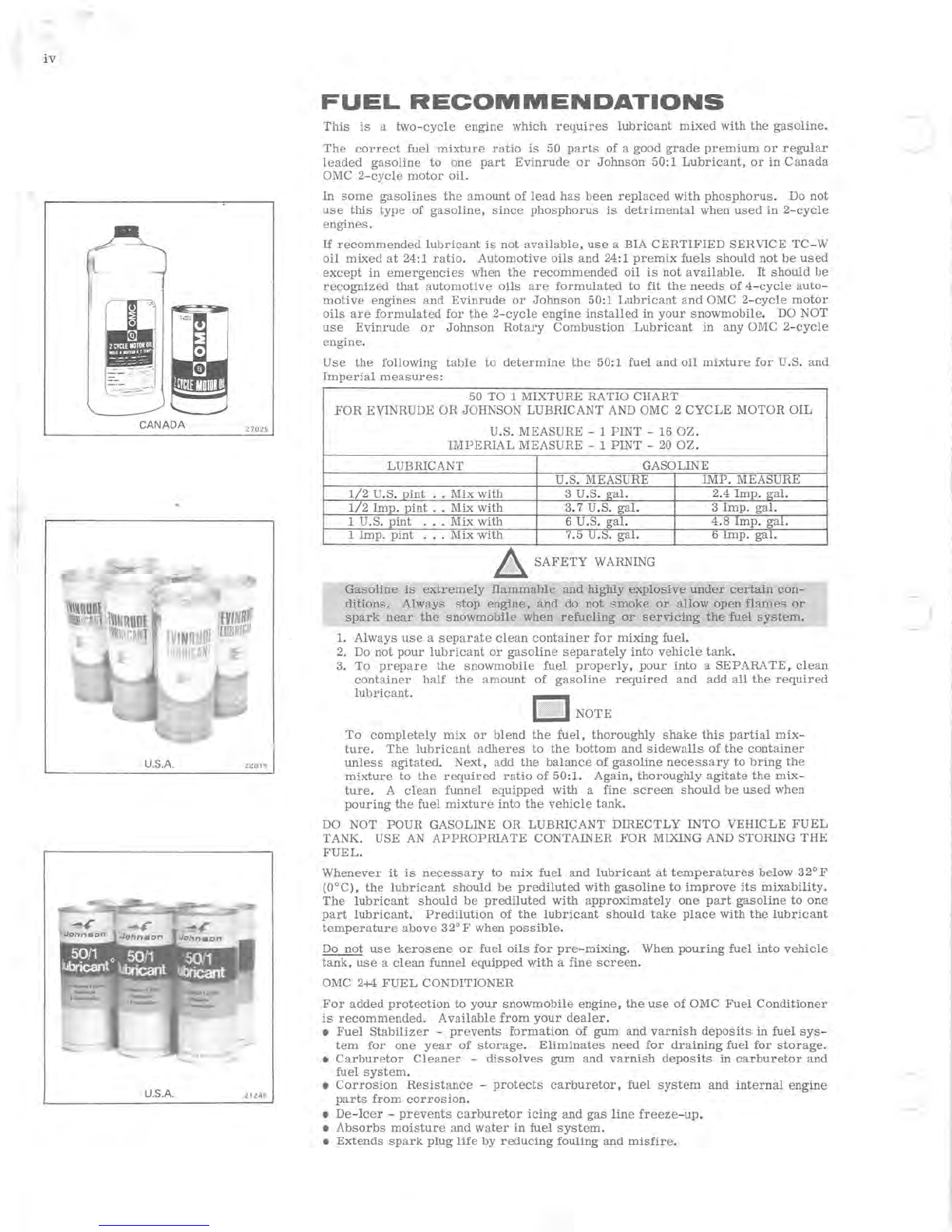
FUEL
RECOMMENDATIONS
This
is
a
two-cycle
engine
which
requires
lubricant
mixed
with
the
gasoline.
The
correct
fuel
mixture
ratio
is
50
parts
of
a good
grade
premium
or
regular
leaded
gasoline
to
one
part
Evinrude
or
Johnson
50:1
Lubricant,
or
in
Canada
OMC
2-cycle
motor
oil.
In
some
gasolines
the
amount
of
lead
has
been
replaced
with
phosphorus.
Do
not
use
this
type
of
gasoline,
since
phosphorus
is
detrimental
when
used
in
2-cycle
engines.
If
recommended
lubricant
is
not
available,
use
a BIA
CERTIFIED
SERVICE
TC-W
oil
mixed
at
24:1
ratio.
Automotive
oils
and
24:1
premix
fuels
should
not
be
used
except
in
emergencies
when
the
recommended
oil
is
not
available.
It
should
be
recognized
that
automotive
oils
are
formulated
to
fit
the
needs
of 4-
cycle
auto-
motive
engines
and
Evinrude
or
Johnson
50:1
Lubricant
and
OMC
2-cycle
motor
oils
are
formulated
for
the
2-cycle
engine
installed
in
your
snowmobile.
DO NOT
use
Evinrude
or
Johnson
Rotary
Combustion
Lubricant
in
any
OMC
2-cycle
engine.
Use
the
following
table
to
determine
the
50:1
fuel
and
oil
mixture
for
U.S.
and
Imperial
measures:
50 TO 1 MIXTURE RATIO CHART
FOR
EVINRUDE
OR
JOHNSON LUBRICANT AND OMC 2
CYCLE
MOTOR
OIL
U.S. MEASURE - 1
PINT
-16
OZ.
IMPERIAL
MEASURE - 1
PINT
-
20
OZ
.
LUBRICANT GASOLINE
U.S. MEASURE
IMP.
MEASURE
1/2
U.S.
pint
..
Mix
with
3 U.S.
gal.
2.4
Imp.
gal.
1/2
Imp.
pint
..
Mix
with
3.7 U.S.
gal.
3
Imp.
gal.
1 U.S.
pint
.. . Mix
with
6 U.S.
gal.
4.8
Imp.
gal.
1
Imp.
pint
.. .
Mix
with
7.5 U.S.
gal.
6
Imp.
gal.
&.
SAFETY
WARNING
Gasoline
is
extremely
flammable
and
highly
explosive
under
certain
con-
ditions.
Always
stop
engine,
and
do not
smoke
or
allow
open
flames
or
spark
near
the
snowmobile
when
refueling
or
servicing
the
fuel
system.
1.
Always
use
a
separate
clean
container
for
mixing
fuel.
2. Do
not
pour
lubricant
or
gasoline
separately
into
vehicle
tank.
3.
To
prepare
the
snowmobile
fuel
properly,
pour
into
a SEPARA
TE,
clean
container
half
the
amount
of
gasoline
required
and
add
all
the
required
lubricant.
U
irlll!t
UNOTE
To
completely
mix
or
blend
the
fuel,
thoroughly
shake
this
partial
mix-
ture.
The
lubricant
adheres
to
the
bottom
and
sidewalls
of
the
container
unless
agitated.
Next,
add
the
balance
of
gasoline
necessary
to
bring
the
mixture
to
the
required
ratiO
of
50:1.
Again,
thoroughly
agitate
the
mi.x-
ture.
A
clean
funnel
equipped
with
a
fine
screen
should
be
used
when
pouring
the
fuel
mixture
into
the
vehicle
tank.
DO NOT
POUR
GASOLINE
OR
LUBRICANT
DIRECTLY
INTO VEHICLE
FUEL
TANK. USE
AN
APPROPRIATE
CONTAINER
FOR
MIXING AND STORING
THE
FUEL.
Whenever
it
is
necessary
to
mix
fuel
and
lubricant
at
temperatures
below
32°F
(O°C),
the
lubricant
should
be
prediluted
with
gasoline
to
improve
its
mixability.
The
lubricant
should
be
prediluted
with
approximately
one
part
gasoline
to
one
part
lubricant.
Predilution
of
the
lubricant
should
take
place
with
the
lubricant
temperature
above
32°F
when
possible.
Do
not
use
kerosene
or
fuel
oils
for
pre-mixing.
When
pouring
fuel
into
vehicle
tank,
use
a
clean
funnel
equipped
with
a
fine
screen.
OMC 2+4
FUEL
CONDITIONER
For
added
protection
to
your
snowmobile
engine,
the
use
of
OMC
Fuel
Conditioner
is
recommended.
Available
from
your
dealer.
•
Fuel
Stabilizer
-
prevents
formation
of
gum
and
varnish
deposits
in
fuel
sys-
tem
for
one
year
of
storage.
Eliminates
need
for
draining
fuel
for
storage.
•
Carburetor
Cleaner
-
dissolves
gum
and
varnish
deposits
in
carburetor
and
fuel
system.
•
Corrosion
Resistance
-
protects
carburetor,
fuel
system
and
internal
engine
parts
from
corrosion.
•
De-Icer
-
prevents
carburetor
icing
and
gas
line
freeze-up.
•
Absorbs
moisture
and
water
in
fuel
system.
•
Extends
spark
plug
life
by
reducing
fouling
and
misfire.

1-1
SECTION
1
INTRODUCTION
AND
SAFETY
WARNINGS
The
snow
machine
has
been
designed
and
built
for
dependable, high
performance.
It
is
important
to
every
snow
machine
owner
to
be
able
to
receive
skilled
and
thorough
service
for
his
vehicle
when
necessary.
It
is
important
to
the
service
dealer
to be
able
to
offer
the type
of
skilled
service
which will
maintain
the
customer's
satisfaction.
This
manual,
together
with
the
regularly
issued
service
bulletins
and
Parts
Catalogs,
provide
the
serviceman
with
all
the
literature
necessary
to
service
this
snowmobile.
An
effort
has
been
made
to
produce
a
manual
that
will
not
only
serve
as
a
ready
reference
book
for
the
ex-
perienced
serviceman,
but
will
also
provide
more
basic
information
for
the
guidance
of
the
less
experienced
man.
The
Parts
Catalogs
contain
complete
listings
of
the
parts
required
for
replacement.
In
addition,
the
exploded
views
illustrate
the
correct
sequence
of
all
parts.
This
catalog
can
be
of
considerable
help
as
a
reference
during
disassembly
and
reassembly.
The
Table
of
Contents
on
page
i
enables
the
reader
to
locate
quickly
any
desired
section.
Section
2
lists
complete
specifications
on
the
snowmobile.
All
general
information,
including
2
cycle
engine
theory,
troubleshooting,
and
tune up
procedures,
are
given
in
Sections
3
through
5
of
this
manual.
Sections
6
through
11
provide
fully
illustrated,
de-
tailed,
step-by-step
disassembly
and
reassembly
instructions
and
ad-
justment
procedures.
Section
12
provides
lubrication
and
storage
in-
formation.
In
this
way,
the
texts
treat
each
topic
separately;
theory
and
practice
are
not
intermixed.
This
makes
it
unnecessary
for
the
experienced
serviceman
to
reread
discussions
of
theory
along with
specific
service
information.
Illustrations
placed
in
the
margins
pro-
vide
unimpeded
reading
of
explanatory
test,
and
permit
close
relation-
ship
between
illustration
and
text.
Figure
1-1
4
70
11
1-2
Read
this
manual
carefully
to
become
thoroughly
familiar
with
the
procedures
as
described,
then
keep
it
readily
available
in
the
service
shop
for
use
as
a
reference.
If
properly
used,
it
will
enable
the
ser-
viceman
to
give
better
service
to
the
snowmobile
owner,
and
thereby
build
and
maintain
a
reputation
for
reliable
service.
This
service
manual
covers
all
phases
of
servicing
the
snowmobile,
however,
new
service
situations
sometimes
arise.
If
a
service
question
does
not
appear
to
be
answered
in
this
manual,
you
are
invited
to
write
to
the
Service
Department
for
additional
help.
Always
be
sure
to
give
complete
information,
including
model
number
and
vehicle
serial
number.
All
information,
illustrations,
and
specifications
contained
in
this
literature
are
based
on
the
product
information
available
at
the
time
of
publication.
The
right
is
reserved
to
make
changes
at
any
time
without
notice.
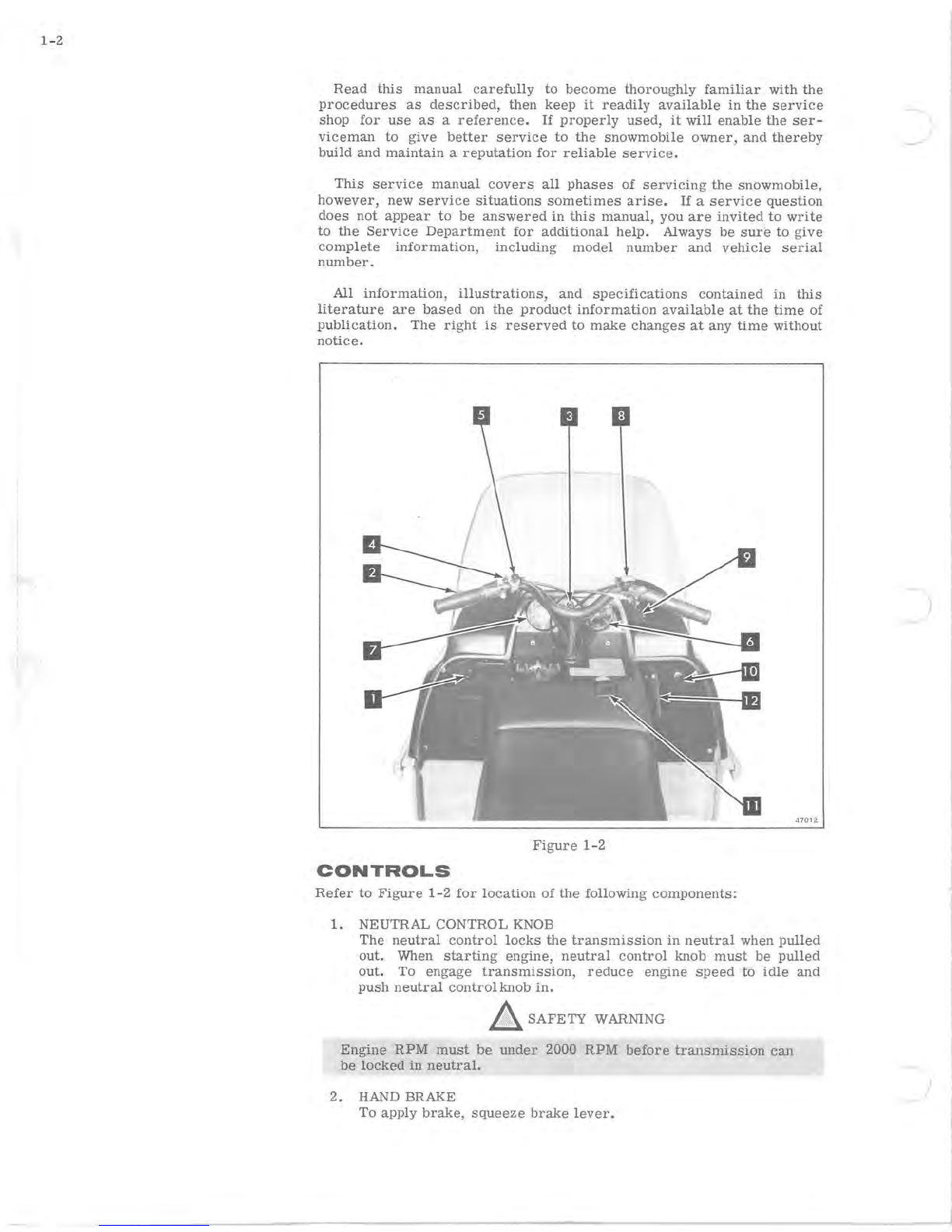
47012
Figure
1-2
CONTROLS
Refer
to
Figure
1-2
for
location
of
the
following
components:
1. NEUTRAL CONTROL KNOB
The
neutral
control
locks
the
transmission
in
neutral
when
pulled
out.
When
starting
engine,
neutral
control
knob
must
be
pulled
out.
To
engage
transmission,
reduce
engine
speed
to
idle
and
push
neutral
control
knob
in.
A SAFETY WARNlNG
Engine
RPM
must
be
under
2000
RPM
before
transmission
can
be
locked
in
neutral.
2. HAND BRAKE
To apply
brake,
squeeze
brake
lever.
3.
IGNITION/LIGHTS SWITCH
The
key
operated
ignition
switch
has
four
positions,
'OFF,'
'RUN/
LIGHTS'
(operate
with
lights),
'RUN'
(operate
without
lights),
and
'ST
ART'
(for
use
with
accessory
electric
start).
4.
PARKING LOCK
To
apply
parking
lock,
with
brake
engaged,
flip
parking
lock
into
position.
To
release,
squeeze
brake
lever.
5.
HI
~
LOW
BEAM HEADLAMP SWITCH
The
headlamp
beam
switch
selects
either
high
beam
or
low
beam
when
ignition
switch
is
in
the
RUN/LIGHTS
position.
6.
SPEEDOMETER/ODOMETER
The
speedometer/odometer,
which
indicates
MPH
and
miles
traveled,
is
an
accessory.
7. TACHOMETER
The
tachometer,
which
indicates
engine
RPM,
is
an
accessory.
8.
SAFETY
STOP
SWITCH
This
switch
allows
the
operator
to
stop
engine
power
instantly.
Rotate
switch
to
either
side
of "RUN"
position
to
stop
engine.
Rotate
switch
to
"RUN"
position
to
allow
restarting
of
engine.
9.
THROTTLE
The
thumb
operated
throttle
lever
is
located
on
the
right
hand
steering
bar.
Squeezing
the
throttle
increases
engine
speed
and
power
is
transmitted
to
the
track.
When
lever
is
released,
engine
returns
to
idle.
10. CHOKE C.ONTROL KNOB
The
choke
control
is
used
during
starting
and
engine
warm-up
to
enrich
the
fuel-air
mixture
to
the
engine.
Pull
to
choke.
11.
PRIMER
Pushing
the
primer
knob
manually
pumps
fuel
into
the
intake
manifold.
A
cold
engine
should
be
primed
prior
to
starting.
12.
MANUAL
STARTER
HANDLE
Snowmobile
is
started
by
pulling
the
manual
starter
handle.
&:.
SAFETY
WARNINGS
-All
operators
must
be
properly
instructed
in
the
operation
of
the
ve-
hicle.
Many
dangerous
situations
are
created
by
negligence.
-When
operating
a
snowmobile,
wear
protective
clothing
and
head-
gear
such
as
a
brightly
colored
helmet
as
well
as
padded
clothes.
DO
NOT WEAR LOOSE CLOTHING
such
as
scarves,
tassel
caps,
etc.
Such
clothing
could
get
entangled
with
the
machinery,
branches
or
other
objects
and
cause
personal
bodily
injury.
It
is
recom-
mended
that
operator
and
passenger
wear
helmets
which
meet
the
requirements
of
ANSI Z90.1 -1971
or
equivalent.
-Do
not
overload
vehicle
with
passenger.
-Keep
feet
on
running
board
at
all
times.
-
Use
headlight
for
early
morning,
evening
and
night
operation.
Use
headlight
in
heavily
wooded
areas
during
the
day.
-Do
not
operate
vehicle
on
or
around
sled,
ski,
and
toboggan
hills.
-
Do
not
operate
vehicle
at
maximum
speeds
in
other
than
a
supervised,
charted
area.
Be
certain
no one
is
behind
unit
when
making
a
fast
start,
as
ice,
stones,
etc.,
may
be
thrown
into
the
air
by
lugs
on
the
track.
1-3

1-4
-
Extra
caution should be
exercised
when
using
vehicle
on
ice.
Steering
control
is
greatly
reduced
on
ice.
Beware
of thin
ice.
Always
use
two hands
for
steering.
-When
crossing
plowed
roads,
approach
with
caution.
Do not jump
snow banks
as
you
might
find
yourself
in
the
path
of oncoming
traffic.
-
Do
not
operate
vehicle
on
bare
ground
or
gravel
as
steering
response
may
be
reduced.
-Do
not
execute
"blind
jumps."
Snow
drifts
can
hide
tree
stumps,
logs
and
excessive
drop
offs.
-
Do
not
smoke
while
operating
vehicle.
Ashes
can
be
dangerous
to
passengers
as
well
as
operator.
-Do
not
operate
vehicle
while
under
the
influence
of intoxicating
bev-
erages,
narcotics
or
other
habit
forming
drugs.
-
Never
leave
the
machine
unattended while engine
is
running.
-Remove key
from
vehicle
whenever
it
is
not
in
use.
-
Wear
goggles to
protect
the
eyes
from
lashing
tree
and
shrub
branches,
and
from
wind and
sun
glare.
Goggles should
meet
the
requirements
of
Vehicle
Equipment
Safety
Commission
regulation
VESCO -
8.
Do
not
attempt
to
perform
repairs
on
your
vehicle
while engine
is
running.
Before
servicing
any
part
of the engine
or
drive
unit:
always
dis-
connect
spark
plug
wires
to
prevent
accidental
start
of engine; and
turn
the
ignition
switch
to
"OFF"
position
to
discharge
the
high
volt-
age
capacitor.
A
charged
capacitor
could give a
severe
electrical
shock.
Never
remove
a fuel
hose
without
first
removing
the
tie
rap
clamp.
Never
attempt
to
install
a fuel
hose
with a
tie
rap
preassembled.
Always
assemble
the
tie
rap
after
the
fuel
hose
is
assembled
to
the
nipple.
Improper
assembly
could
result
in
a
leak.
All
reassembled
tie
raps
should
be
located
in
the
original
assembled
location.
~
PROHIBITED
-
Operation
on
private
property
without
owner's
permission.
Operation
of
vehicle
on public
roads,
streets
or
highways
unless
it
is
legal
to do
so.
(
2-1
SECTION
2
SPECIFICATIONS
AND
SPECIAL
SERVICE
TOOLS
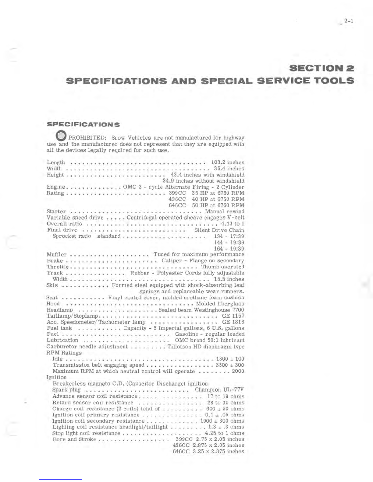
SPECIFICATION
S
o
PROHIBITED:
Snow
Vehicles
are
not
manufactured
for
highway
use
and
the
manufacturer
does
not
represent
that
they
are
equipped
with
all
the
devices
legally
required
for
such
use.
Length
•......••.••.•••.••••.•••••••••...
103.2
inches
Width
.•..........••.•.•...•.....•••••.••.
35.4
inches
Height.
• . . • • • . • • • • . • . . • • • . • • •
•.
43.4
inches
with
windshield
34.9
inches
without
windshield
Engine
•..••.•.•.••.•
OMC 2 -
cycle
Alternate
Firing
- 2
Cylinder
Rating
•.•....••.•.•....•••••.•.
399CC
35
HP
at
6750
RPM
436CC
40
HP
at
6750
RPM
646CC 50
HP
at
6750
RPM
Starter
•.••.••••••.•...•..•••..•...•.•.•
Manual
rewind
Variable
speed
drive
..••.
Centrifugal
operated
sheave
engages
V
-belt
Overall
ratio
...•..•.......•.•..•..••••••••..•
4.43
to
1
Final
drive
..•.••••.•••••••••••••...•
Silent
Drive
Chain
Sprocket
ratio
standard
••.•.......•
,.........
13'4
-17:39
144 -19:39
164 -19:39
Muffler
• • • . . . . • • . . • . . . • . .
..
Tuned
for
maximum
performance
Brake
• • • . . . . • • • • • . . • . . • . . •
•.
Caliper
-
Flange
on
secondary
Throttle.
• • • . . • • . . . • • • • . . . . • • . . . . • • . • •
..
Thumb
operated
Track
. . . • • . . . • • . . .
.•
Rubber
-
Polyester
Cords
fully
adjustable
Width.
. • • • • . • . • . . . • • • . • • • • • . . . • • • . . • . •
•.
15.5
inches
Skis
•.....•..•.•
Formed
steel
equipped
with
shock-absorbing
leaf
springs
and
replaceable
wear
runners.
Seat
.••••.•...
•
Vinyl
coated
cover,
molded
urethane
foam
cushion
Hood
..•.•...•....•.••••••••..•••••••
Molded
fiberglass
Headlamp
....••.•....•...•...
Sealed
beam
Westinghouse
7700
Taillamp
/
Stoplamp.
. . . . . • • . . • • • . . • • • . . • • . • . • . •
•.
GE 1157
Acc.
Speedometer
/
Tachometer
lamp
••.....••••••.••.
GE 1816
Fuel
tank
•....••••..
Capacity
- 5
Imperial
gallons,
6 U.S.
gallons
Fuel
. . . . . . . . . . . . . . . . . . . . . . . . .
..
Gasoline
-
regular
leaded
Lubrication
.
.....................
OMC
brand
50: 1 lul::ricant
Carburetor
needle
adjustment
.........
Tillotson
HD
diaphragm
type
RPM
Ratings
Idle
.•.....•••••••••.••..•••..••....•..•.
1300 ± 100
Transmission
belt
engaging
speed
••••.•...•••.••••
3300 ± 300
Maximum
RPM
at
which
neutral
control
will
operate
.•••.•..
2000
Ignition
Breakerless
magneto
C.D.
(Capacitor
Discharge)
ignition
Spark
plug
••.•••••••••••••••••••••••
Champion
UL-77V
Advance
sensor
coil
resistance.
. . . . . . . . . . . . .
..
17
to
19
ohms
Retard
sensor
coil
resistance
...
........
.....
28
to
30
ohms
Charge
coil
resistance
(2
coils)
total
of . . . . . . . .
..
600 ± 50
ohms
Ignition
coil
primary
resistance
. . . . . . . . . . . . .
..
0.1
± .05
ohms
Ignition
coil
secondary
resistance.
. . . . . . . . . . . . 1900 ± 300
ohms
Lighting
coil
resistance
headlight/taillight
.........
1.3 ± .3
ohms
Stop
light
coil
resistance
...................
'
4.25
to
1
ohms
Bore
and
Stroke.
. . . . . . . . . . . . . . .
..
399CC
2.75
x
2.05
inches
436CC 2.875 x
2.05
inches
646CC
3.25
x 2.375
inches
2-2
Piston
displa
c
ement
35
HP
399CC
.................
24.35
cu.
in.
40
HP
436CC
.............
.. ..
26.62
cu. in.
50
HP
646CC
.................
39.40
cu
in.
Cylinder
compression
........................
100
to
120
psi
End
gap.
. . . . . . . . . . . . . . . . . . . . . . . . . . . . . . . .
..
.007 -.017
Specifications
and
features
may
be
changed
at
any
time
without
noti
ce
and
without
obligation
towards
vehicles
previously
ma
nufacturer.
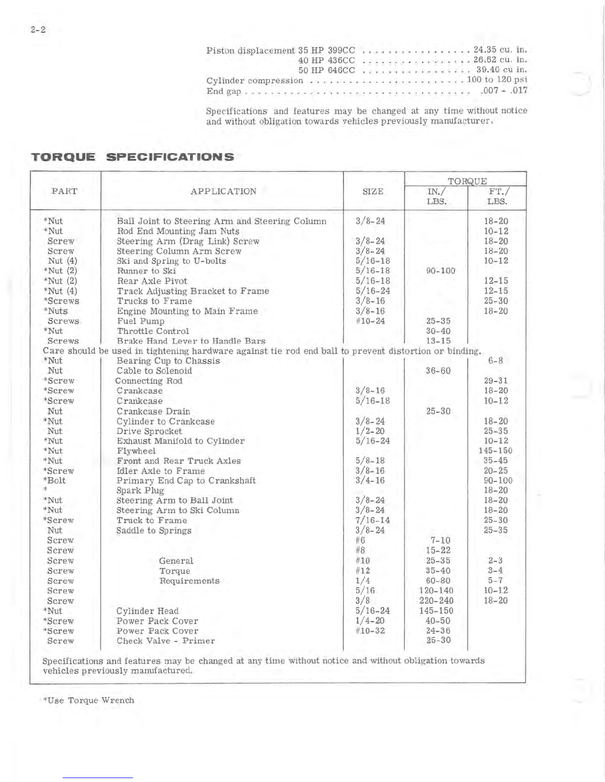
TORQUE
SPECIFICATIONS
TORQUE
PART
APPLICATION
SIZE
IN./
FT./
LBS. LBS.
*Nut
Ball
Joint
to
Steering
Arm
and
Steering
Column
3/8-24
18-20
*Nut Rod
End
Mounting
Jam
Nuts
10-12
Screw
Steering
Arm
(Drag
Link)
Screw
3/8-24
18-20
Screw
Steering
Column
Arm
Screw
3/8-24
18-20
Nut (4)
Ski
and
Spring
to
U-
bolts
5/16-18
10-12
*Nut (2)
Runner
to
Ski
5/16-18
90-100
*Nut
(2)
Rear
Axle
Pivot
5/16-18
12-15
*Nut
(4)
Track
Adjusting
Bracket
to
Frame
5/16-24
12-15
*Screws
Trucks
to
Frame
3/8-16
25-30
*
Nuts
Engine
Mounting
to
Main
Frame
3/8-16
18-20
Screws
Fuel
Pump
#
10-24
25-35
*Nut
Throttle
Control
30-40
Screws
Brake
Hand
Lever
to
Handle
Bars
13-15
Care
should
be
used
in
tightening
hardware
against
tie
rod
end
ball
to
prevent
distortion
or
binding.
*Nut
Bearing
Cup
to
Chassis
6":'8
Nut
Cable
to
Solenoid
36-60
*Screw
Connecting
Rod
29-31
*Screw
Crankcase
3/8-16
18-20
*Screw
Crankcase
5/16-18
10-12
Nut
Crankcase
Drain
25-30
*
Nut
Cylinder
to
Crankcase
3/8-24
18-20
Nut
Drive
Sprocket
1/2-20
25-35
*Nut
Exhaust
Manifold
to
Cylinder
5/16-24
10-12
*Nut
Flywheel
145-150
*Nut
Front
and
Rear
Truck
Axles
5/8-18
35-45
*Screw
Idler
Axle
to
Frame
3/8-16
20-25
*Bolt
Primary
End
Cap
to
Crankshaft
3/4-16
90-100
*
Spark
Plug
18-20
*Nut
Steering
Arm
to
Ball
Joint
3/8-24
18-20
*Nut
Steering
Arm
to
Ski
Column
3/8-24
18-20
*Screw
Truck
to
Frame
7/16-14
25-30
Nut
Saddle
to
Springs
3/8-24
25-35
Screw
#6
7-10
Screw
#8
15-22
Screw
General
#10
25-35
2-3
Screw
Torque
#12
35-40
3-4
Screw
Requirements
1/4
60-80
5-7
Screw
5/16
120-140
10-12
Screw
3/8
220-240
18-20
*Nut
Cylinder
Head
5/16-24
145-150
*Screw
Power
Pack
Cover
1/4-20
40-50
*Screw
Power
Pack
Cover
#
10-32
24-36
Screw
Check
Valve
-
Primer
25-30
Specifications
and
features
may
be
changed
at
any
time
without
notice
and
without
obligation
towards
vehicles
previously
manufactured.
*Use
Torque
Wrench
2-3
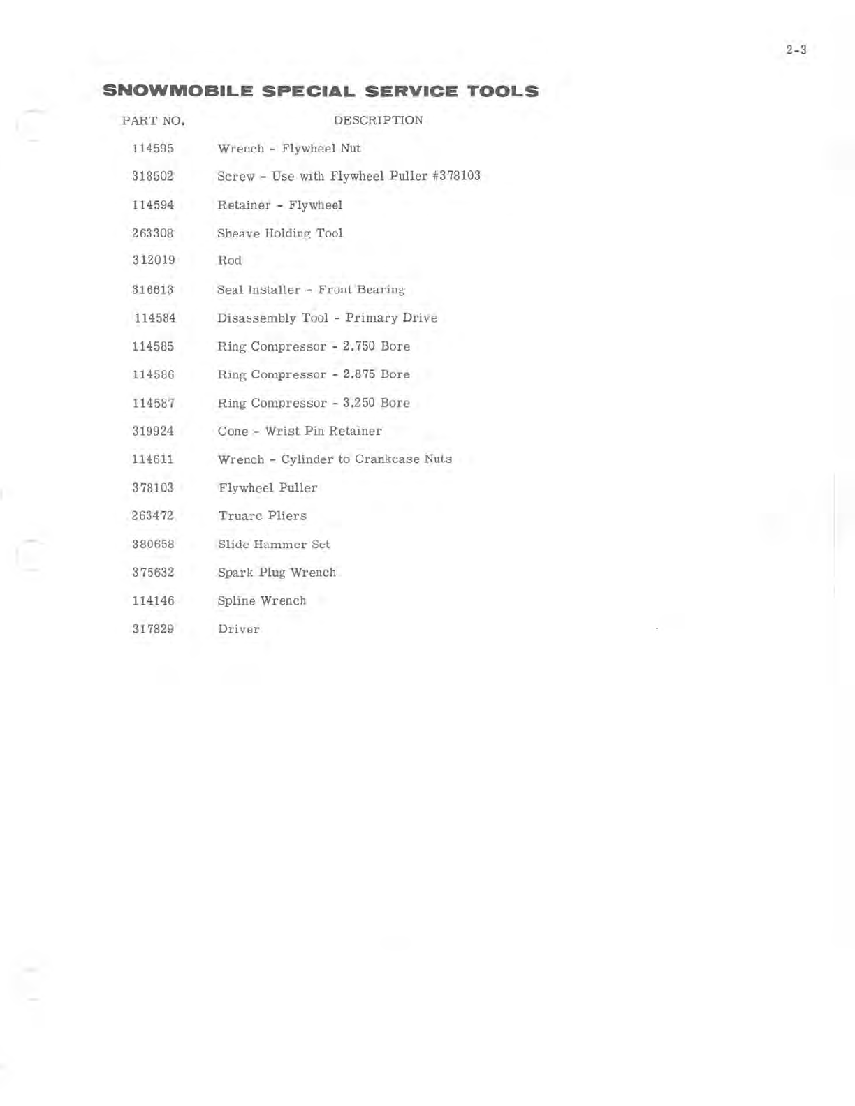
SNOWMOBILE
SPECIAL
SERVICE
TOOLS
-
PART
NO. DESCRIPTION
114595
Wrench
-
Flywheel
Nut
318502
Screw
-
Use
with
Flywheel
Puller
#378103
114594
Retainer
-
Flywheel
263308
Sheave
Holding
Tool
312019
Rod
316613
Seal
Installer
-
Front
Bearing
114584
Disassembly
Tool
-
Primary
Drive
114585
Ring
Compressor
-2.750
Bore
114586
Ring
Compressor
-2.875
Bore
114587
Ring
Compressor
-
3.250
Bore
319924
Cone
-
Wrist
Pin
Retainer
114611
Wrench
-
Cylinder
to
Crankcase
Nuts
378103
Flywheel
Puller
263472
Truarc
Pliers
380658
Slide
Hammer
Set
375632
Spark
Plug
Wrench
114146
Spline
Wrench
317829
Driver

)

-
3-1
SECTION
3
GENERAL
SNOWMOBILE
INFORMATION
TWO-STROKE
CYCLE
ENGINE
THEORY
As
the
piston
leaves
bottom
dead
center
(BDC),
it
creates
a
depres-
sion
in
the
crankcase
causing
air
to
flow
in
thru
the
carburetor.
Fuel
is
added
to
this
air
in
the
proper
proportion
for
combustion
and
the
air-
fuel
mixture
(charge)
then
passes
thru
the
reed
spring
inlet
valve
to
the
crankcase
.
The
next
time
the
piston
moves
toward
BDC
it
compresses
the
charge
in
the
crankcase
and
as
the
top edge of
the
piston
uncovers
the
transfer
port
the
pressurized
charge
is
forced
into
the
cylinder
on
the
combustion
chamber
side
of
the
piston.
The
piston
then
reverses
direction
and
in
moving
toward
TDC
it
closes
the
transfer
port
and
the
exhaust
port
respectively.
The
secondary
compression
of
the
charge
takes
place
at
this
time.
As
the
piston
nears
the
top
of
the
stroke
this
charge
is
ignited
by
means
of
an
electric
spark.
The
pressure
formed
by
the
burning
gases
forces
the
piston
back
toward
BDC. When
the
top
edge
of
the
piston
uncovers
the
exhaust
port,
the
burned
gases
begin
to
leave
the
cylinder.
A
little
more
travel
of
the
piston
opens
the
trans-
fer
port
and
the
incoming
charge
forces
the
remaining
burned
gases
out
while
the
piston
moves
past
BDC.
As
it
moves
back
toward
TDC
closing
the
transfer
port
and
subsequently
the
exhaust
port
it
begins
the
secondary
compression
mentioned
earlier.
This
cycle
repeats
itself
once
each
engine
revolution
which
consists
of
two
strokes
of
the
piston,
one
from
BDC
to
TDC
and
one
from
TDC
to
BDC.
Consequently
the
engine
utilizing
this
basic
principle
is
called
a
two-stroke
cycle
engine.
It
can
be
seen
then
that
the
two-stroke
cycle
engine
achieves
basically
the
same
operation
as
the
more
commonly
understood
four-stroke
cycle
engine.
The
intake,
compression,
power
and
exhaust
strokes
of
the
four-stroke
cycle
engine
become
the
induction,
primary
compression,
transfer,
secondary
compression,
power
and
exhaust
all
taking
place
during
two
strokes
of
the
piston.
CARBURETION
GaSOline,
in
its
liquid
state,
burns
relatively
Slowly
with
an
even
flame.
However,
when gaSOline
is
combined
with
air
to
form
a
vapor,
the
mixture
becomes
highly
inflammable
and
burns
with
an
explosive
effect.
To
obtain
best
results,
the
fuel
and
air
must
be
correctly
pro-
portioned
and
thoroughly
mixed.
It
is
the
function of
the
carburetor
to
accomplish
this.
Gasoline
vapor
will
burn
when
mixed
with
air
in
a
proportion
from
12:1
to
18:1 by
weight.
Mixtures
of
different
proportions
are
required
for
different
purposes.
Idling
requires
a
relatively
rich
mixture;
a
leaner
mixture
is
desirable
for
maximum
economy
under
normal
load
conditions;
avoid
lean
mixtures
for
high
speed
operation.
The
carbure-
tor
is
designed
to
deliver
the
correct
proportion
of
fuel
and
air
to
the
engine
for
these
various
conditions.
The
carburetor
is
essentially
a
simple
metering
device.
A
diaphragm
and
valve
system
allows
a
constant
fuel
supply
to
be
maintained
in
the
INDUCED
LOW
VENTURI
PRESSURE
L
-~~
______
~·~*~n
---+
I=======~==~===
FUEL FORCED UPWARDS
BY ATMOSPHERIC PRESSURE
Figure
3-1
1713
6

3-2
/'
/'
'ij'
)
REED PLATE AND BASE ASSEM.
170
88
Figure
3-2
metering
chamber
at
just
slightly
below
atmospheric
pressure.
Needle
valves
permit
a
precise
amount
of
fuel
to flow
from
the
metering
chamber
to
the
carburetor
throat.
The
upstroke
of
the
piston
creates
a
suction
which
draws
air
through
the
leaf
valves
and the
carburetor
throat
. At a
particular
point
the
throat
is
restricted
by a
venturi
(see
Figure
3-1). The
venturi
has
the
effect
of
reducing
air
pressure
in
the
air
stream,
creating
a
partial
vacuum
which
draws
fuel
from
the
dis
-
charge
port.
As
it
is
rushed
along to
the
firing
chamber,
the
fuel
is
swirled
about
in
the
air
stream
and
vaporized.
A
throttle
or
butterfly
valve
in
the
throat
regulates
the
amount
of
air
drawn
through
the
carburetor.
To
vary
the
speed
of
the
engine,
the
throttle
opens
or
closes,
regulating
the
amount
of
fuel-air
mixture
drawn
into
the
engine.
A
richer
fuel
mixture
is
required
for
starting
a
cold
engine.
A
sec-
ond
shutter,
called
a choke,
is
placed
into
the
throat
forward
of
the
jets,
to
restrict
the
flow
of
air.
When
the
choke
shutter
is
closed,
more
gas-
oline
and
less
air
is
allowed
into
the
air
stream
resulting
in
a
richer
fuel-
air
mixture.
When
normal
operating
temperature
is
reached,
the
choke
is
opened
and
the
standard
ratio
of
gasoline
and
air
allowed
to
flow
from
the
carburetor.
The
system
which
controls
the
intake
of
the
fuel-air
mixture
in
the
two
cycle
engine
consists
of a
set
of
valves
which
serve
the
same
pur-
pose
as
the
intake
valves
on a
four
cycle
engine.
The
reed
valves
are
thin,
flexible
metal
strips
mounted
between
the
carburetor
intake
mani-
fold and
crankcase.
When
the
piston
is
on
the
up-stroke,
it
creates
a
partial
vacuum
in
the
crankcase.
Atmospheric
pressure
forces
the
reeds
away
from
the
body
(see
Figure
3-2),
opening
the
passage
between
the
carburetor
and
crankcase.
When
the
piston
is
on
the
down-stroke,
it
compresses
the
crankcase
charge,
forcing
the
reeds
against
the
passage
opening, and
sealing
off
the
crankcase
from
the
carburetor.
8ince
the
opening
and
closing
may
occur
in
excess
of
seven
thousand
times
per
minute,
the
reeds
must
be
thin
and
flexible.
IGNITION
Two
charge
COils,
are
mounted on
the
alternator
stator,
located
under
the
flywheel.
The
same
flywheel
magnets
which
induce
current
in
the
alternator
stator
also
generate
about 300
volts
A.C.
in
the
charge
coils
as
the
flywheel
rotates.
No
external
voltage
source
is
required.
The
300
volts
A.C.
is
converted
to D.C.
in
the
Power
Pack
28,
and
is
stored
in
the
Power
Pack
28
capacitor.
One gap
between
the
sensor
magnets,
part
of
the
flywheel hub,
passes
the
sensor
coil,
also
under
the
flywheel.
h
lw,lm
UNOTE
One thing
to
note
in
this
system
is
that
there
are
two
sensor
coils.
Below
the
idle
RPM
range
and
up to
apprOximately
900
RPM,
the
retard
sensor
turns
on
the
electronic
switch
in
the
Power
Pack
28. At
RPMs
over
900
the
advance
sensor
coil
generates
enough
voltage
to
turn
on
the
electronic
switch
in
the
Power
Pack
28
before
the
retard
sensor
does.
80, we
have
an
automatic
electronic
advance
built
into
the
system.
The
small
voltage
generated
in
the
sensor
coil
activates
one
of
two
electronic
switches
in
the
POWER PACK 28.
This
switch
discharges
the
300
volts
stored
in
the
capacitor
into
one of
the
ignition
coils.
The
ignition
coil
steps
the
voltage
up
to
30,000
volts,
which
is
fed
to
the
spark
plug. When
the
capaCitor
is
discharged,
the
electronic
switch
opens
and
allows
the
charge
coils
to
again
charge
the
capacitor.
The
second
sensor
magnet
gap,
opposite
in
polarity
from
the
first,
generates
a
reverse
polarity
voltage
in
the
sensor
coil.
This
activates
the
second
electronic
switch
in
the
POWER PACK 28, and
discharges
the
capacitor
into
the
other
ignition
coil.
I

-
LIGHTING
SYSTEM
The
alternator
coils
produce
alternating
current
which
changes
in
frequency
at
approximately
constant
voltage
in
proportion
to
the
engine
speed.
The
alternator
A.C.
output
is
used
to
operate
lamps.
POWER
FLOW
The
transmission
assembly
transmits
power
from
the
engine
to
the
front
axle
which
propels
the
vehicle
along
the
track.
The
primary
sheave
assembly
is
attached
directly
to
the
crankshaft.
The
secondary
sheave
assembly
has
its
own
mounting
pedestal
and
is
larger
in
diam-
eter
than
the
primary
sheave
assembly.
The
two
are
connected
by
a
transmission
belt.
PRIMARY DRIVE
The
primary
sheave
is
centrifugally
operated
and
engages
the
trans
-
mission
belt
when
the
engine
speed
reaches
3000 -3600
RPM.
When
the
engine
is
rotating
at
idle
speed
or
below
3000 -3600
RPM,
the
transmission
belt
rides
on a
ball
bearing
between
the
halves
of
the
primary
sheave
assembly
(see
Figure
3-3) .
The
primary
sheave
as-
sembly
halves
are
separated
by a
compression
spring
in
the
hub
of
the
movable
sheave
half.
E
B G
0
N
M
L
TRANSMISSION
LOCKED
IN
NEUTRAL
Figure
3-3
As
the
engine
speed
increases,
centrifugal
effect
forces
a
garter
spring
in
the
end
cap
outward
against
the
contour
of
the
end
cap
and
axially
against
the
movable
sheave
half.
As
the
sheaves
are
brought
together,
the
transmission
belt
is
forced
outward
to
ride
on a
larger
diameter
of
the
primary
sheave
assembly,
increasing
belt
speed
(see
Figure
3-4).
Since
the
belt
length
remains
constant,
the
secondary
sheave
halves
spread
apart,
allowing
the
belt
to
ride
on a
smaller
diam
-
eter.
In
this
way,
the
engine
transmits
power
through
a
variable
ratio,
presenting
the
engine
with a
mechanical
advantage
most
favorable
for
the
speed
at
which
it
is
operating.
3-3
A.
Flywheel
Nut
B.
Emergency
Starting
Sheave
C.
Garter
(Activating)
Spring
D.
End
Cap
E.
Movable
Half
of
Sheave
F.
Transmission
Belt
G.
Fixed
Sheave
/
Flywheel
H.
Ball
Bearin
g
I.
Spring
Cup
J.
Compression
Spring
K.
Neutral
Lockout
Balls
L.
Splined
Shaft
(crankshaft)
M.
Bolt,
End
Cap
to
Splined
Shaft
N.
Spring
o.
Neutral
Lockout
Rod
P.
Spacer
37
1
38

3-4
TRANSMISSION HIGH
SPEED
POSITION -
BELT
ENGAGED
Figure
3-4
NEUTRAL
CONTROL
A neutral control mechanism
is
used
to
prevent the drive from engag-
ing
during
starting,
warm-up
period,
and
idle.
When
the
neutral
lockout
plunger
is
actuated,
a
cone
on
the
end
of
the
plunger
raises
two
balls
through
the
splines
of
the
primary
sheave
assembly
and
into
the
path
of
the
movable
sheave
half,
preventing
it
from
engaging
the
belt.
The
neutral
control
is
spring
actuated
and
will
engage
only
when
the
engine
is
below
approximately
2000
RPM.
371
39
NEUTRAL
CONTROL NOT
FUNCTIONING BECAUSE
RPM
TOO HIGH
Figure
3-5
37140
When
the
engine
is
running
above
approximately
2000
RPM
the
garter
spring
will
expand
by
centrifugal
effect.
See
Figure
3-5.
The
garter
spring
will
then
ride
up
the
ramp
of
the
end
cap
and
push
the
movable
sheave
toward
the
fixed
sheave.
In
dOing
this,
the
movable
sheave
has
covered
the
holes
in
the
splined
shaft
and
the
neutral
lockout
balls
can
not
be
pushed
into
the
locked
position.
If
the
engine
speed
is
now
reduced
to
below
2000
RPM,
the
garter
spring
will
close
and
allow
the
movable
half
of
the
sheave
to
move
away
from
the
fixed
sheave.
SECONDARY DRIVE
The
secondary
drive
mechanism
incorporates
a
torque
sensing
device
that
detects
the
need
for
more
power
for
steep
inclines
or
deep
snow.
The
mechanism
immediately
forces
the
secondary
sheaves
closer
to-
gether
to
lower
the
transmission
ratio
and
provide
a
higher
torque
to
the
drive
chain
and
track.
The
drive
ratio
varies
from
3
to
1
in
low
to
1
to
.68
in
high
which
yields
an
overall
drive
range
of
approximately
4.4
to
1.
Power
is
trans
-
mitted
from
the
secondary
sheave
assembly
through
a
drive
chain
to
the
front
axle.
The
ratio
between
the
secondary
sheave
assembly
and
the
front
axle
is
17:39
or
19:39.
)

4-1
SECTION
4
TROUBLE
SHOOTING
DESCRIPTION
This
section
provides
trouble
shooting
procedures
for
the
snow
ma-
chine.
Steps
to
be
followed
in
determining
causes
of
unsatisfactory
per-
formance
are
outlined.
Being
able
to
locate
the
cause
of
trouble
in
an
improperly
operating
snow
machine
is
as
important
as
being
able
to
correct
the
trouble.
A
systematic
approach
to
trouble
shooting
is
important
if
the
trouble
is
to
be
located
and
identified
in
minimum
time.
Any
service
operation
oan
be
broken
down
into
three
steps:
1.
Identifying
the
problem
2.
Determining
the
cause
of
the
problem,
and
3.
Correcting
the
problem.
Familiarity
with
the
factors
which
affect
two-cycle
engine
perform-
ance
is
important
in
making
a
correct
service
diagnosis.
Factors
which
affect
engine
performance
include
the
quality
of
the
fuel
and
fuel
mixtures,
compression,
ignition,
and
proper
drive
system
adjustment.
Engine
theory,
compression,
carburetion,
ignition
and
power
flow
are
discussed
in
Section
3.
Correct
fuel
mixture
for
this
snowmobile
is
outlined
on
page
iv,
and
fuel
blending
is
discussed
in
Section
12.
Familiarity
with
factors
which
contribute
to
abnormal
performance
of
an
engine
are
similiarly
helpful.
The
skilled
mechanic's
experience
is
a
great
asset
here.

4-2
TROUBLE
SHOOTING
PROCEDURES
Trouble
shooting
to
determine
the
cause
of
any
operating
problem
may
be
broken
down
into
the
fol-
lowing
steps:
a.
Obtaining
an
accurate
description
of
the
trouble.
b.
Preliminary
inspection.
c.
Use
of
Trouble
Check
Chart
to
analyze
engine
performance.
An
accurate
description
of
the
trouble
is
essential
for
trouble
shooting.
The
owner's
comments
may
provide
valuable
information
which
will
serve
as
a
clue
to
the
cause
of
the
problem.
A
preliminary
inspection
should
include
the
follow-
ing
checks.
a.
Correct
spark
plugs
b.
Throttle
linkage
properly
adjusted
c.
Tank
filled
with
fresh,
clean
fuel
of
the
proper
mixture
d.
Spark
at
each
spark
plug
e.
Carburetor
adjusted
correctly
f.
Compression.
Turn
flywheel by
hand
or
with
recoil
starter.
If
compression
is
present,
it
can
be
felt
when
turning
through
one
complete
revolution
of
the
flywheel.
If
little
or
no
com-
pression
exists
in
both
cylinders,
engine
will
spin
very
easily.
STARTING
1.
Hard
to
start
or
won't
start
a.
Empty
gas
tank
b.
Incorrect
gas-lubricant
ratio
c.
Old fuel,
or
water
or
dirt
in
fuel
system
d.
Fuel
line
improperly
connected
e.
Fuel
line
kinked
or
severely
pinched
f.
Engine
not
primed
g.
Clogged
fuel
line
or
fuel
filter
h.
Clogged
check
valve
i.
Carburetor
adjustments
too
lean
j.
Low
speed
needle
bent
or
bowed
k.
Engine
flooded
1.
Reed
valves
not
functioning
properly
m.
Faulty
gaskets
n.
Spark plugs fouled, dirty
or
broken
o.
Loose
or
broken
wire
or
frayed
insulation
in
ignition
system
wiring
p.
Sheared
flywheel
key
q.
Faulty
coils
r.
Key
switch,
connector
or
grounded
switch
wire
s.
Binding
in
engine
t.
Faulty
sensor,
charge
coils,
Power
Pack
2S
or
connecting
wiring.
2. Engine
won't
turn
over
a.
Cylinder
wall
corrosion,
seized
piston
or
bearing
b.
Engine
improperly
assembled
after
repair
3.
Cranks
over
extremely
easily
a.
Spark
plug(s)
loose
b.
Cylinder
or
pistons
scored
c.
Rings
worn
or
carboned
d.
Faulty
cylinder
head
gasket
4.
Won't
start,
but
kicks
back
and
backfires
a.
Spark
plug
leads
crossed
b.
Reed
valves
broken
or
not
seating
c.
Timing
out
of
adjustment
(check
with
timing
light)
d.
Retard
sensor
faulty
or
out
of
adjustment
e.
Power
Pack
2S
faulty
5. No
spark
one
cylinder
a.
Faulty
ignition
coil,
Wire,
or
connections
b.
Faulty
Power
Pack
2S
6. No
spark
both
cylinders
a.
Faulty
charge
coil
b.
Faulty
sensor
coils
c.
Faulty
Power
Pack
2S
d.
Grounded
ignition
switch
and/or
wire
e.
Broken
or
poor
ground
)

(
--------
~
-
---
f.
Flywheel
not
properly
charged
g.
Faulty
ignition
coils
or
leads
7.
Weak
spark
both
cylinders
a.
Ignition
switch
or
connection
leakage
b.
Weak
charge
coil
output
c.
Weak
Power
Pack
2S
output
d.
Weak
ignition
coil
output
e.
Poor
ground
8.
Engine
can
be
started
by
using
primer,
but
dies
out
when
primer
is
not
used
a.
Fuel
pump
inoperative
b.
Carburetor
needle
valves
closed
c.
Fuel
line
to
carburetor
clogged
d.
Fuel
filter
screen
in
fuel
pump
or
carburetor
inlet
screen
clogged
e.
Carburetor
inoperative
STARTING -MANUAL
STARTER
1.
Manual
starter
pulls
out,
but
starter
does
not
engage
flywheel
a.
Friction
spring
bent
b.
Pinion
or
rope
pulley
burred
c.
Pinion
frozen
(water)
in
place
d.
Roll
pin
fallen
out
or
broken
2.
Starter
rope
does
not
return
a.
Return
spring
broken
or
binding
b.
Grease
on
return
spring
c.
Not
enough
preload
on
return
spring
3.
Clattering
manual
starter
a.
Bearing
missing
or
worn
b.
Pinion
or
rope
pulley
worn
c.
Main
spring
improperly
assembled
d.
Pinion
return
spring
broken
STARTING -
ELECTRIC
STARTER
1.
Starter
cranks
too
slowly
a.
Weak
battery
4-3
b.
Loose
or
corroded
connections
c.
Faulty
starter
solenoid
or
solenoid
wiring
d.
Worn
armature
brushes
or
springs
e.
Faulty
armature
(shorted
or
open
windin
gs)
2.
Starter
will
not
crank
engine
a.
Weak
battery
b.
Loose
or
corroded
connections
c.
Broken
wire
in
harness
or
connector
d.
Faulty
ignition
key
switch
e.
Faulty
starter
solenOid
or
solenOid
wiring
f.
MOisture
in
starter
motor
or
bendix
g.
Broken
or
worn
brushes
or
broken
brush
springs
h.
Faulty
armature
(shorted
or
open
windings)
i.
Dirty
bendix
RUNNING -LOW
SPEED
ONLY
1.
Low
speed
miss
a.
Incorrect
gas
-
lubricant
ratio
b.
Carburetor
idle
adjustment
too
lean
or
too
rich
c.
Reed
valve
standing
open
or
preloaded
shut
d.
Spark
plugs
dirty
or
broken
e.
Loose
or
broken
ignition
coil
wires
f.
Spark
plug
terminal
loose
g.
Weak
coil
output
h.
Cylinder
gasket
or
reed
plate
gasket
dam-
aged
i.
Leaking
crankcase
gaskets
or
crankshaft
seal
j.
Arcing
around
ignition
coils
or
arCing
in
ig-
nition
switch
k.
Loose
connections
or
intermittent
grounding
of
leads
in
the:
ignition
coil,
Power
Pack
2S,
charge
coils,
sensor
coils,
and
ignition
switch
RUNNING -HIGH
SPEED
ONLY
1.
High
speed
miss
a.
Water
in
fuel
This manual suits for next models
5
Table of contents
Other Evinrude & Johnson Offroad Vehicle manuals


