EVO Products EP 1236-100 User manual

Page 1
Instruction Manual
Read the instruction manual
carefully before using the
equipment for the first time
and before carrying out any
maintenance work.
For the following models:
EP 123 -100
EP 123 -100 Sensor
EP 123 -140
Serial number:
__________________________________________
(status: August 2011)

Page 2
Page 2
Table of contents:
1. Introduction
2. General information/Identifying data
Des ription of the nameplate
3. General safety precautions
4. Important technical information
5. Delivery
Unloading, unpa king
Installing the va uum leaner
Conne ting to the power supply
. Switching on and off
Duty time
7. Using the vacuum cleaner
Appropriate use
Residual risk analysis
8. Disposing of dirt
Emptying the dirt box
9. Cleaning and replacing cartridge filter
10. Checks and inspections
Prior to every shift
After 200 hours of operation (monthly)
After 2000 hours of operation (yearly)
11. Troubleshooting
At the end of the instruction manual:
EC declaration of conformity

Page 3
Page 3
1. Introduction
The person using this equipment is responsible for its operational safety.
Read the instruction manual carefully before using the equipment for the
first time and before carrying out any maintenance work.
Operators must be aware of potential accident risks and have received
instruction in respect of appropriate safety precautions.
This instru tion manual must be kept in the vi inity of the equipment at all times, in a se ure,
dry pla e away from dire t sunlight. It should always be a essible when needed.
2. General information/Identifying data
This industrial va uum leaner is suited for va uuming various liquids, ooling lubri ants and
swarfs whi h a umulate during produ tion and metal working pro esses. The leaner
separates the swarfs from the liquids. The swarfs remain in the swarf basket and the liquids
tri kle into the lower ontainer.
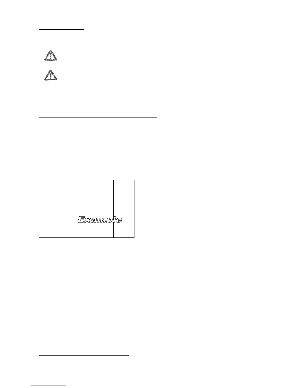
For identifi ation purposes, please refer to the important data relating to power
onsumption, dust lass or leaner serial number, whi h appears on the nameplate (see the
example below):
Modell/Typ:
XXXX
1
Staubklasse:
L/M
2
Nennspannung: 230/400 Volt
3
Nennaufnahme: kW
4
Phasenzahl: 1
5
Frequenz: 50/60 Hz.
S hutzart: IP 33
7
Herstellerangaben
8
Adresse
Serien
-
Nr.:
070000001
9
Key:
1 = Model name
2 = Dust lass usage ategory
3 = Rated voltage in volts
4 = Rated onsumption in kW
5 = No. of phases
(1 = AC, 3 = DC)
6 = Frequen y in hertz
7 = Degree of prote tion
8 = Manufa turer
9 = Serial number
You will need to provide all of the above information whenever you onta t Customer
Servi e. Identifying the equipment model and serial number uniquely ex ludes the risk of
in orre t information being supplied.
3. General safety precautions

Page 4
Page 4
• Prior to installation, first use, maintenan e or use of the va uum leaner, you must first
familiarise yourself thoroughly with the ontent of this instru tion manual.
• Only authorised persons may use the equipment.
• Do not wear open or loose lothing whi h may get aught in the va uum leaner.
• The area in whi h maintenan e work (s heduled and extraordinary) is arried out must
always be lean and dry.
Repair work may only be carried out once the equipment has been switched
off and disconnected from the power supply.
• Repair work may only be arried out by spe ialist personnel.
• The ma hine must not be left out in the rain or standing in water. Neither must it be used
in su h onditions.
• This equipment is not a toy and must not be used as su h. Pro eed with extreme aution
when using the equipment in the vi inity of hildren.
• Do not insert obje ts into the vents. Do not use the equipment if a vent is blo ked. Do
not allow the vents to be ome logged with dust, fibres, hair or other materials whi h
may restri t air flow. Keep hair, loose lothing, fingers and other body parts away from
vents and moving parts.
• Do not use the equipment if the power able or onne tor is damaged.
• You must stop using the equipment immediately if:
it is not in perfe t working order
it falls to/is dropped on the floor
it shows eviden e of external damage
it gets wet or is dropped into water.
In su h ases, it will need to be he ked by Customer Servi e.
• Never move or arry the equipment by pulling on the power able. Make sure that the
able does not get trapped in doors and is not routed via sharp orners or edges. Never
allow the equipment to run over the power able. Keep the able away from hot
surfa es. Do not tou h the onne tor or equipment with wet hands.
If a problem o urs when using the equipment in spite of omplian e with the instru tion
manual, swit h it off immediately and dis onne t it from the power supply.

Page 5
Page 5
4. Important technical information
Caution!
The equipment must be earthed.
The equipment is fitted with a able whi h features an earth ondu tor and an earth
onne tor. The onne tor must be plugged into an appropriate earthed power so ket whi h
has been installed in omplian e with lo al standards and regulations.
Conne ting the earth ondu tor in orre tly an in rease the risk of ele tri sho k. If you are
not sure whether the mains supply has been earthed orre tly, seek advi e from a qualified
ele tri ian or spe ialist. Do not modify the equipment or onne tor supplied with it in any
way. If it annot be onne ted to your mains supply, have a qualified ele tri ian fit a suitable
power so ket.
• Do not extend the power able. The use of extension ables, onne tion ouplings or
adapters is not permitted.
• The ma hine must undergo an annual te hni al inspe tion to be arried out by the
manufa turer or a qualified spe ialist.
Caution!
Unauthorised tampering with the equipment is stri tly forbidden!
Any attempt on the part of a user or unauthorised person to open or modify the equipment
or any unauthorised tampering with any omponent thereof will invalidate the warranty.
The use of repla ement parts or a essories supplied by third parties other than the
manufa turer or approved supplier will also invalidate the warranty.

Page 6
Page 6
5. Delivery
Unloading and unpacking
The equipment is supplied pa ked on a pallet. On re eipt, please he k the equipment for
visible or on ealed damage. If you dis over eviden e of damage, report this immediately to
the arrier, ensuring that the relevant details are onfirmed and re orded.
Caution!
Only a forklift tru k with suffi ient arrying apa ity should be used to lift the
equipment.
The va uum leaner an be stored at temperatures between 5° and 40° and at up to 65%
relative humidity. You must make sure that the load- arrying apa ity of the floor is suffi ient
to support the weight of the ma hine.
The equipment an be used at temperatures between -5° and 40° and at up to 65% relative
humidity.
Manufa turer approval must be sought if you wish to use the equipment in other onditions.
The pa kaging in whi h the equipment is shipped must be disposed of in omplian e with
the requirements of appli able national legislation.
Equipment whi h is no longer suitable for use must also be disposed of in omplian e with
the requirements of appli able legislation.
Installing the vacuum cleaner
It is the user’s responsibility to ensure that the va uum leaner is installed in omplian e
with lo al regulations.
This instru tion manual must be read and its ontent understood.
The floor on whi h the va uum leaner is to be pla ed must be even and solid and have a
suffi ient load-bearing apa ity.
Conne t the hose and the asso iated a essories (e.g. revi e tool) to the ports on the
va uum leaner.
Connecting to the power supply
Caution!
Che k whether the voltage, frequen y and ele tri al fusing of the power supply tally
with the information on the nameplate.
Caution!
Repair work may only be arried out on e the equipment has been swit hed off and
dis onne ted from the power supply.
The power able may only be repla ed by a qualified ele tri ian. To repla e the power
able, you will need to open the ontrol box. Make sure that the earth ondu tor has been
onne ted orre tly.

Page 7
Page 7
The able may only be repla ed with one of the type H07 RN-F 3G 1,5 mm² with a fuse of
1 Ampere.
. Switching on and off
Caution!
Only authorised persons may operate this industrial va uum leaner. The user must
he k omplian e with all prote tive measures and safety pre autions.
Move the va uum leaner near to the area to be leaned and apply the parking brake.
All models feature a ombined ON/OFF swit h. Press this swit h on e and the leaner will
start.
Now the leaner is ready for operation and swarfs as well as liquids an be va uumed.
The va uumed swarfs are olle ted – depending on the onstru tion type of the va uum
leaner – in the swarf basket or on the installed swarf separation bottom, whi h is inside the
dirt box. The liquids/emulsions tri kle into the lower ontainer.
For version with ele troni al liquid level ontrol (sensor):
As soon as the maximum level is rea hed the probe of the liquid level ontrol rea ts, the
indi ator light illuminates and the leaner disrupts the su tion pro ess automati ally.
Dirt box and swarf basket have to be emptied now.
If the indi ator light remains on even on e the dirt box and the swarf basket have been
emptied, this an mean that the probe used for he king the liquid level has be ome
ontaminated. The probe is lo ated in the dirt ontainer and must be leaned as
appropriate.
For version with filling-level hose:
If the liquid rea hes the maximum level (see arrow „maximum“) the leaner has to be shut
down and the dirt box must be emptied.
Attention!
The vis ous slime whi h originates on ooling lubri ants owing to mi robial
ontamination should be disposed of separately from the ontainer; sin e through
the vis osity of that slime the swarf basket’s vents may be sealed and the passing
resp. draining of other liquids will be hampered.
Duty time:
Single phase machines:
Suitable for periodi use.
Prolonged duty lasting more than 90 minutes must be followed by a ooling-down period of
at least 30 minutes.

Page 8
Page 8
7. Gebrauch des Staubsaugers
This va uum leaner must ONLY be used to pi k up substan es deemed suitable a ording
to the information on its nameplate. In orre t use or misuse will invalidate the warranty.
Appropriate use:
This industrial va uum leaner is suited for va uuming various liquids, ooling lubri ants and
swarfs whi h a umulate during produ tion and metal working pro esses. The leaner
separates the swarfs from the liquids. The swarfs remain in the swarf basket and the liquids
tri kle into the lower ontainer.
Residual risk analysis
If the instru tion manual is omplied with and work pro eeds in a ordan e with the
operating sequen es it des ribes whilst appli able safety pre autions are taken by
operators, the va uum leaner should pose no risk in normal operation.
However, if the va uum leaner is used to pi k up a variety of substan es, there remains the
risk of these substan es ombining to produ e an unforeseeable hemi al rea tion.
. Disposal of dirt:
Emptying the swarf basket and dirt container:
• Run the va uum leaner hose empty.
• Swit h off the ma hine by a tuating the ON/OFF swit h.
• The liquid an be drained through the draining hose.
• EP 1236-100: Lower the dirt ontainer through the levers on both sides
EP 1236-140: Loosen tension lamps and take down the motor head
• The swarfs an now be disposed of separately. For this purpose tip the dirt ontainer out
or remove the swarf basket (only for models with swarf basket).
Caution!
Dirt must be disposed of in omplian e with appli able legal requirements for waste
disposal and/or hazardous waste disposal.
Attention!
The vis ous slime whi h originates on ooling lubri ants owing to mi robial
ontamination should be disposed of separately from the ontainer; sin e through
the vis osity of that slime the swarf basket’s vents may be sealed and the passing
resp. draining of other liquids will be hampered.

Page 9
Page 9
9. Cleaning or changing of the cartridge filter
The artridge filter is installed under the lid of the dirt ontainer (su tion lid). This artridge
filter prevents the intrusion of dirt into the motor.
If the leaner operates with diminished apa ity, the artridge filter has to be leaned. If the
artridge filter itself is damaged, it must be repla ed by a artridge filter of the same
onstru tion and same hara teristi s.
For leaning or hanging the artridge filter please pro eed as follows:
• Swit h off the leaner by a tuation of the OFF-swit h.
• Loosen the tension ring or tension lamps of the motor head.
• For model „Sensor“: loosen the ele tri al onne tion of the liquid level ontrol
• Take down the motor head and deposit it arefully.
• Twist off the s rew joint of the artridge filter.
• Pull the artridge filter from the pipe so ket and repla e it by a new artridge filter of the
same onstru tion and hara teristi s.
• If the filter should only be leaned, you an do that now. The filter onsists of water-
tolerant polypropylene and an be wet leaned.
Achtung!
Der Patronenfilter muss zur Reinigung aus dem Gerät entnommen werden.
Note!
For leaning the artridge filter has to be taken out of the devi e.
• If you position a new or leaned artrdige filter onto the pipe so ket and tighten the
s rew joint, pay lose attention to the perfe t and stable seating of the artridge filter.
• Position the motor head on the ontainer
• Tighten tension ring or tension lamps and pay attention to a perfe t seating!
Attention !
Pay attention to the right seating of the motor head and the tension ring/ tension
lamps!
• The leaner is now again ready for operation.

Page 10
Page 10
Checks and inspections
Prior to every shift
Che k that:
• All seals are tight.
• All safety devi es are fully operational.
• The dirt box is empty.
• The filter is in good working order (see pressure gauge). If the pointer is in the red
zone, lean the filter or he k the tubes/hoses.
Every 200 hours of operation (monthly)
Che k that:
• The va uum leaner is airtight. There are no leaks.
• The su tion hose and tool are in good ondition. They must not be torn, split or
damaged beyond repair.
• The power able is not damaged, twisted or squashed.
• The loth artridge filter is not damaged and that there is no eviden e of any tears or
holes. If the filter is damaged, you must repla e it.
• The probe is free of ontamination.
Every 2000 hours of operation (yearly)
• Che k the ondition of the su tion unit (side hannel blowers).
• Have the va uum leaner undergo a general inspe tion by the manufa turer or an
authorised Customer Servi e Centre.

Page 11
Page 11
Motor not running
• Swit h, supply able, onne tor or fuses are faulty.
Solution: Have the faulty omponent he ked by a qualified ele tri ian and repla ed if
ne essary.
• If indi ator light is on: Dirt box is full.
Solution: Empty the dirt box.
• If indi ator light is on: Probe used for he king the liquid level is heavily
ontaminated.
Solution: Clean the probe.
• If indi ator light is still on, the probe is faulty.
Solution: Have the probe repla ed by a spe ialist.
Insufficient suction power
• Filter or hose is blo ked.
Solution: Clean filter or hose.
• Box is full.
Solution: Follow the instru tions in the manual and empty the box.
• Box not airtight.
Solution: Lo ate and re tify the leak.
• Ex essive dirt in the artridge filter.
Solution: Clean filter.
Dust blowing out
• Switch the vacuum cleaner off immediately!
• Filter faulty.
Solution: he k and repla e the filter.
• Filter not suitable.
Solution: he k the filter and repla e it with one with suitable properties.
Electrostatic voltage on cleaner
• In orre t earthing.
Solution: Che k and restore earthing.

Page 12
Page 12
EG-Declaration of conformity
im Sinne der EG-Richtlinie Maschinen 200 /42/EG, Anhang II A
in accordence with machinery directive 200 /42/EG, annex II A
Der Hersteller – The manufa turer –
EVO-PRODUCTS Blankenburg GmbH, Dieselstraße 3, D – 53424 Remagen
Erklärt hiermit dass die folgenden Modelle:
hereby de lares that the following models:
EP 123 -100, EP 123 -100 Sensor, EP 123 -140
Folgenden Normen und Vors hriften entspre hen:
meet the requirements of the following standards and regulations:
Richtlinien/Directives:
2006/42/EG Mas hinen-Ri htlinie - ma hinery dire tive,
2004/108/EG Elektromagnetis he Verträgli hkeit - ele tromagneti ompatibility dire tive
Angewandte harmonisierte Normen/applied harmonized standards:
DIN EN 60335-1 (10/12), DIN EN 60335-2-69 (01/2010)
Si herheitsanforderungen Staub- und Wassersauger– Requirements for wet- and dry va uum
DIN EN ISO 3744 (02/2011) – Bestimmung S halleistungspegel
Nationale Prüfgrundlagen/National testing framework
ZEK 01.4-08 (11/2011)
Poly lis h Aromatis he Kohlenwasserstoffe (PAK) - poly y li aromati hydro arbons (PAH)
Die CE-Kennzei hnung und die EG-Konformitätserklärung verliert bei einer Änderung der Mas hine
ihre Gültigkeit.
The CE marking and the EC de laration of onformity be omes invalid in ase of a modifi ation of
the ma hine.
Remagen, 01/10/2013
Managing dire tor
Volker Blankenburg
_________________________________

Accessories for wet- and swarf-vacuum cleaner
Swarf basket 60 litres
Bottom height adjustable from 190 to 375 mm
Instead of separating plate
optional 053-3090
To bu for replacement
as a spare part 054-30075
Cartridge filter
for swarf and emulsion vacuum cleaner
EP 1 36,
to buy for replacement
1,0 m², dia. 50 cm = 054-10059
PUR suction hose
for swarf and emulsion vacuum cleaner
EP 1 36 with coupler for camlock coupling
3,5 m, dia. 50 mm = 052-0278
5,0 m, dia. 50 mm = 052-0279
Closure for Kamlock-coupling
For suction hose dia. 50 mm
052-0261
EVOTEC

EVOTEC – Accessor sets EVOTEC
Machine cleaning set
optimised for cleaning production
machines.
Consisting of bulk suction nozzle,
beveled tube rubber nozzle, pointed
rubber nozzle and
round brush nozzle
dia. 40 mm = 052-1080
dia. 50 mm = 052-1070
Set for cleaning at height
Consisting of m hand tube,
curved tubular nozzles 100 mm
and 00 mm, one wall nozzle and
one floor nozzle
dia. 40 mm = 052-1090
dia. 50 mm = 052-1100
Industrial floor cleaning set
for cleaning all floors. Consisting of multi-part hand
tube, metal revolving nozzle with brush strip and
replacement rubber strip,
round brush nozzle
dia. 40 mm, working width 370 mm = 052-1030
dia. 40 mm, working width 450 mm = 052-1035
dia. 50 mm, working width 370 mm =052-1040
dia. 50 mm, working width 450 mm = 052-1050
dia. 50 mm, working width 500 mm =052-1060

Metal hose and - components
Hosematerial of metal, enhanced with metalbands and tightthreat. Axiale flexibility,
torsionstability, heat-proof up to 400°C (75 °F). Suitable for dry dusts only.
Metal suction hose,
fiberglass-compressed, couplers alread
installed
3,5 m long, dia. 40 mm = 052-0186
3,5 m long, dia. 50 mm = 052-0271
5 m long, dia. 40 mm = 052-0187
5 m long, dia. 50 mm = 052-0272
linear metres
(for extension or self-manufacturing)
dia. 40 mm = 052-0185
dia. 50 mm = 052-0270
Universal hose coupling (boiler side)
for all hose versions
dia. 80 - 40 mm = 052-0175
dia. 80 - 50 mm = 052-0266
dia. 80 - 60 mm = 054-90013
dia. 80 - 70 mm = 052-0312
Hose coupling (suction side)
for metal hose
dia. 40 mm = 052-0112
dia. 50 mm = 052-0208
PUR hose and - components
Hosematerial of polyuhrethane (PUR), enhanced with integrated spiral made of steel
with convenient couplers. Oil-resistant, very solid and suitable for abrasive dusts.
Heat-proof up to 1 5°C ( 57°F). Well-suitable for extreme industrial usage.
Discharging if spiral is grounded.
PUR suction hose, electricall conductive,
couplers alread installed
3,5 m long, dia. 40 mm = 052-0155
3,5 m long, dia. 50 mm = 052-0252
5 m long, dia. 40 mm = 052-0156
5 m long, dia. 50 mm = 052-0253
linear metres
(for extension or self-manufacturing)
dia. 40 mm = 052-0136
dia. 50 mm = 052-0236
dia. 70 mm = 052-0309
strengthened version:
dia. 40 mm = 052-0157
dia. 50 mm = 052-0254
dia. 70 mm = 052-0310
Hose coupling (suction side)
for PUR hose antistatic
dia. 40 mm = 052-0141
dia. 50 mm = 052-0241
dia. 70 mm = 052-0311
Hose coupling (boiler side)
for PUR hose antistatic
incl. cap screw for coupler
dia. 80 - 40 mm = 052-0160
dia. 80 - 50 mm = 052-0257
EVOTEC

Accessories
Floor nozzle with carpet strip
and lateral rollers
dia. 40 x 400 mm = 052-0118
Replacement carpet strip = 052-0030
Aluminium floor nozzle with rollers and
Brush strip
dia. 40 x 370 mm = 052-0120
dia. 40 x 450 mm = 052-0121
dia. 50 x 370 mm = 052-0213
dia. 50 x 450 mm = 052-0214
dia. 50 x 500 mm = 052-0215
Rubber strip
dia. 40 x 370 mm = 052-0192
dia. 40 x 450 mm = 052-0193
dia. 50 x 370 mm = 052-0276
dia. 50 x 450 mm = 052-0277
Replacement brush strip (aluminium nozzle)
length 370 mm = 052-0173
length 450 mm = 052-0171
length 500 mm = 052-0264
Replacement rubber strip (aluminium nozzle)
length 370 mm = 052-0174
length 450 mm = 052-0172
length 500 mm = 052-0265
Oil resistant rubber strip
length 370 mm = 052-0194
length 450 mm = 052-0195
length 500 mm = 052-0280
Accessories
Chrome-plated curved tube
dia. 36 mm = 052-0014
dia. 40 mm = 052-0111
dia. 50 mm = 052-0209
Chrome-plated hand tube
dia. 36 x 500 mm = 052-0012
dia. 40 x 500 mm = 052-0112
dia. 50 x 500 mm = 052-0208
Floor nozzle with brush strip
and lateral rollers
dia. 40 x 400 mm = 052-0116
dia. 50 x 400 mm = 052-0210
Replacement
brush strip = 052-0026
Floor nozzle with rubber strip
and lateral rollers
dia. 40 x 400 mm = 052-0117
dia. 50 x 400 mm = 052-0211
Replacement rubber strip = 052-0027
EVOTEC
This manual suits for next models
1
Table of contents