Evo Prime1 Operating instructions

Rev.1 1 | P a g e
Prime1 & Prime3
User and Maintenance Manual
Rev
Date
Author/s
Checked
Date
1
20/5/2020
Jack Wright Smith & Richard Smaldino
JA
15/6/20

Rev.1 2 | P a g e
Table of Contents
1. Introduction........................................................ 3
1.1 About the Prime ................................................ 3
1.2 Glossary: ............................................................. 3
1.3 Contact details.................................................. 3
2. Component identification................................ 4
3. Procedures ......................................................... 5
3.1 Emergency Safety Protocol.............................. 5
3.1.1 For all emergencies: ................................. 5
3.1.2 For Flooding:.............................................. 5
3.1.3 For fires: ...................................................... 5
3.1.4 Other emergencies not covered:........... 5
3.2 Shutdown procedure........................................ 5
3.3 Startup procedure............................................. 6
4. Maintenance..................................................... 6
4.1 Filters ................................................................... 6
4.1.1 Air Inlet/Vermin screen............................. 7
4.1.2 Air filters...................................................... 7
4.1.3 Extraction filter........................................... 8
4.2 Internal cleaning ............................................... 8
5. Prime Specifications .......................................... 9
6. APPENDICES: .................................................... 11
APPENDIX A : PRIME1 SCHEMATIC (ON GRID)........ 11
APPENDIX B : PRIME3 SCHEMATIC (ON GRID) ........ 12

Rev.1 3 | P a g e
1. Introduction
1.1 About the Prime
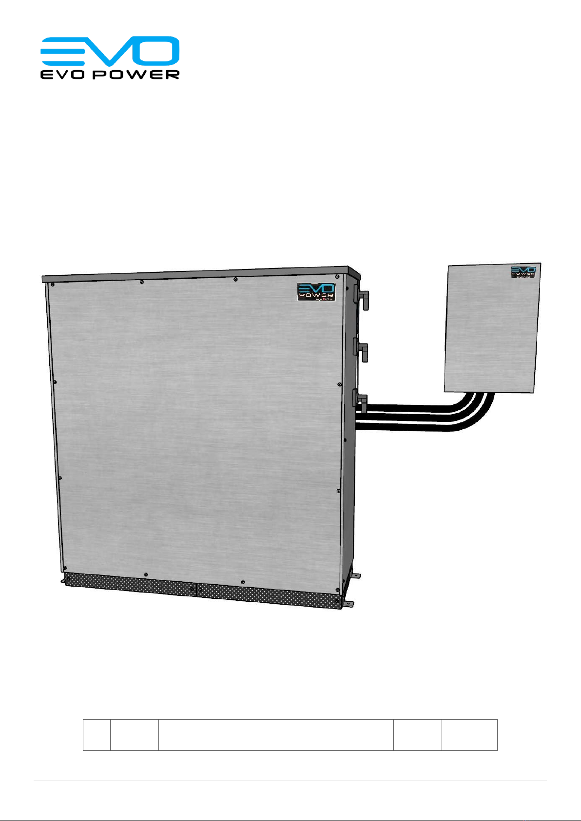
The Prime Series from EVO Power is a compact AC
coupled battery system engineered for the residential
and commercial power markets providing high
flexibility for solar self-consumption, load shifting and
complete off grid power applications.
The Prime series incorporates proven and trusted
hardware with inverters from Selectronic and options from
24kWh to 60kWh of Lithium Ion Batteries from the world’s
leading ESS battery manufacturer, LG Chem.
The purpose of this user manual is to guide and advise
a user on how to safely shutdown and maintain their
EVO Power Prime system. This manual also includes
optional procedures for the user that are
recommended by EVO Power. The instructions that
follow require no specialist skills.
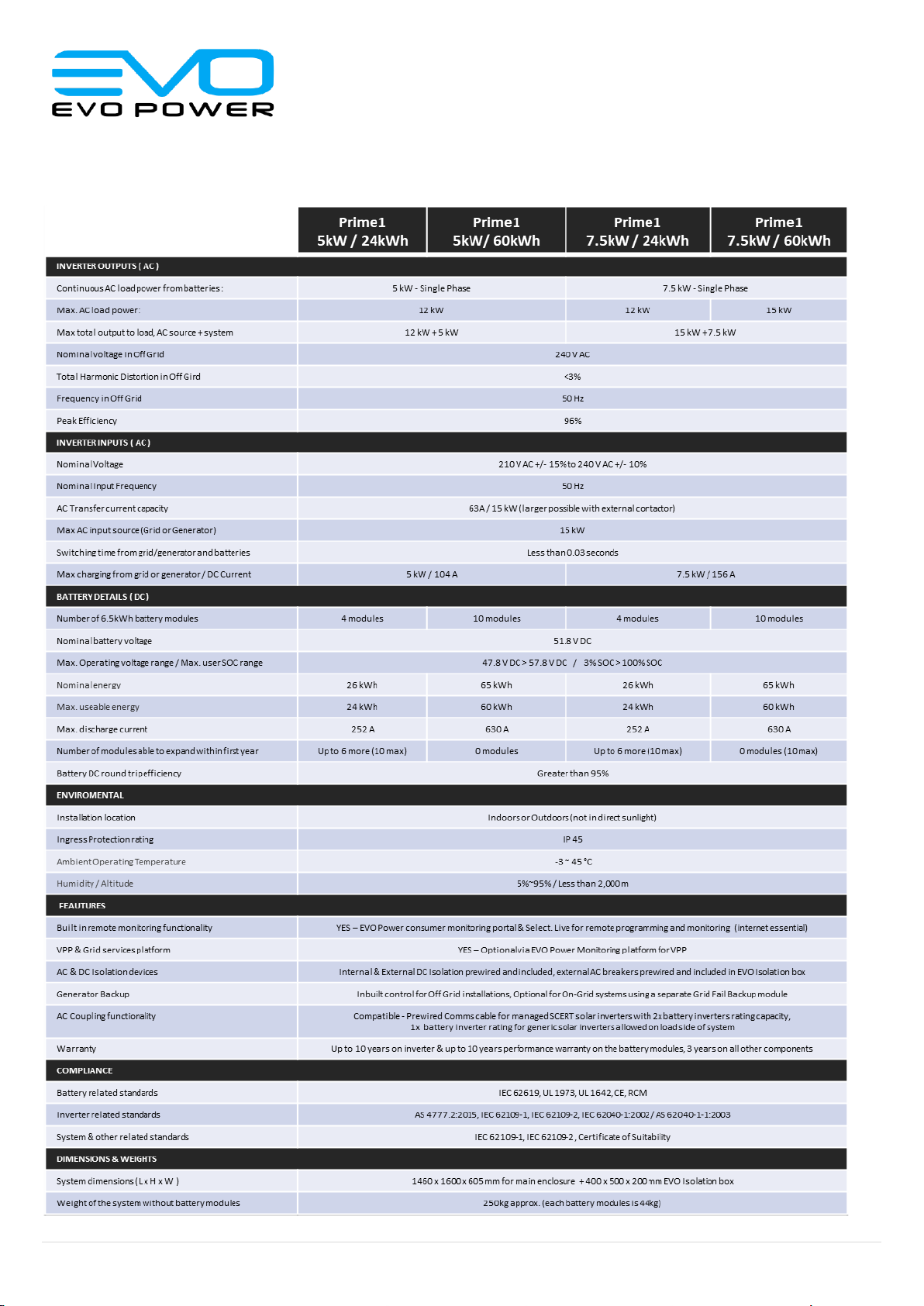
The battery capacity of the Prime1 is between 4-10
battery modules, while the Prime3 requires between 8-
10 battery modules. The amount of battery modules
can be increased or decreased within these specific
module ranges, and these changes must be
completed by an installer.
The Prime1 relates to Single Phase systems and the
Prime3 uses 3 Phase equipment. The inverter capacity
for all Prime models is fixed, but the inverter itself can
be swapped out for a different power capacity.
1.2 Glossary:
Throughout this manual, the following abbreviations will
be used:
AC –Alternating Current
DC –Direct Current
1.3 Contact details
Your first point of contact for operation and warranty
issues is your installer or installation company that sold
you the system. Please record the details at time of
installation;
Installer: ……………………………………………………….
Install Co: …………………………………………………….
Phone: …………………………………………………………
Email: …………………………………………………………
For Emergency services, please contact the
Manufacturer, EVO Power;
Phone: 03 9052 4545
Prime Features & Benefits
Australian made & supported solution
✓Premium quality inverter & battery technology
✓Intelligent remote monitoring and control software
✓Flexible storage from 24 to 60kWh
✓Flexible inverter options in single and 3 phase
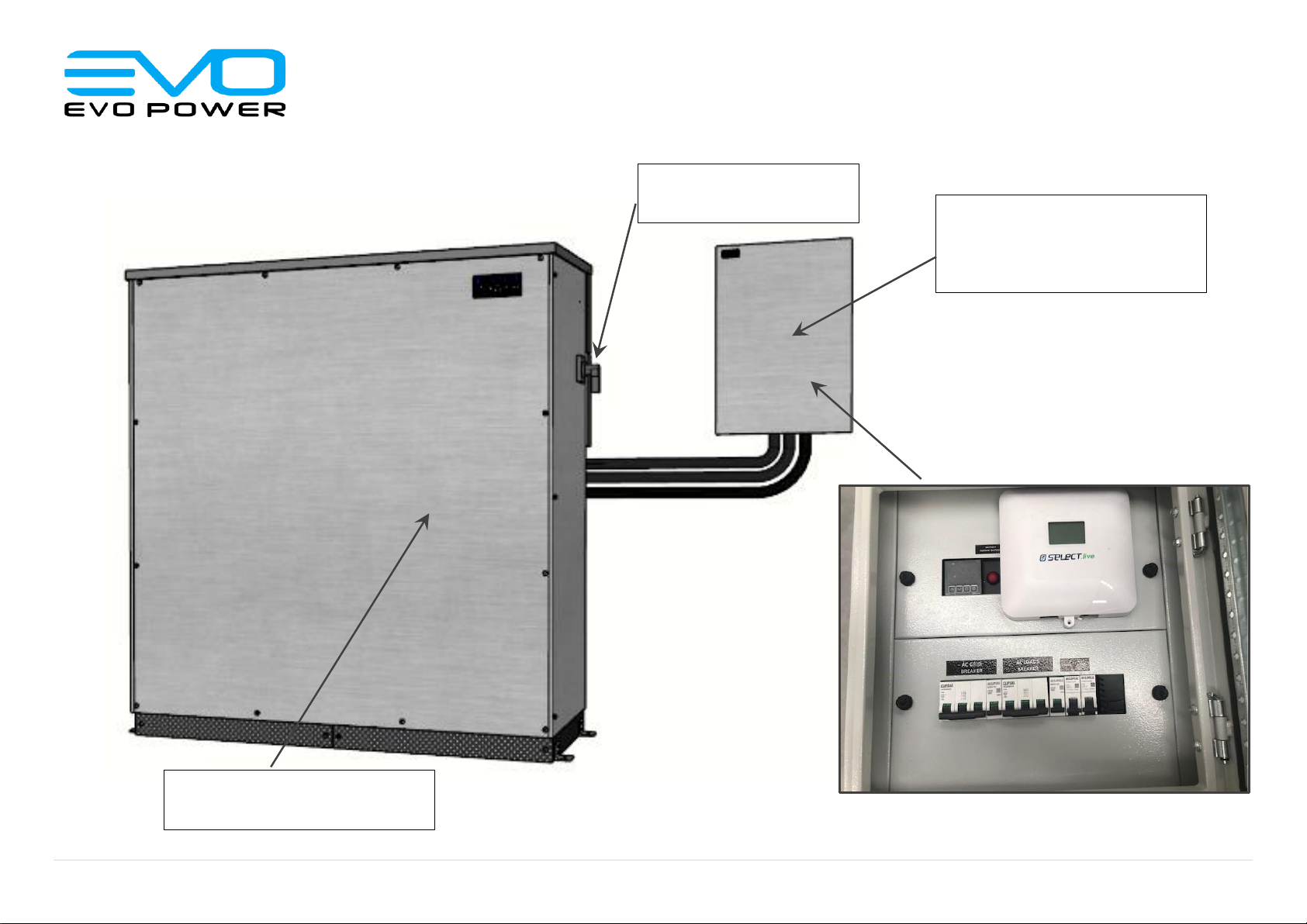
✓IP55 rated compact indoor/outdoor enclosure
✓Prewired enclosure with all isolation devices

Rev.1 4 | P a g e
2. Component identification
Prime Enclosure
Isolation Box -
“Isobox”
DC Isolator/s
Inside of Isobox

Rev.1 5 | P a g e
3. Procedures
3.1 Emergency Safety Protocol
3.1.1 For all emergencies:
oInside Isobox: Turn OFF AC Load Breaker if safe to do so
oTurn OFF AC GRID Breaker if safe to do so
oTurn OFF DC Isolator/s on side of Prime enclosure if safe to do so
oEvacuate the area
oCall relevant emergency services in your area
3.1.2 For Flooding:
oIf system is submerged in water, stay out of water that is connected to submerged system
oDo not attempt to operate the system after being submerged in water, even if the system is dry.
oIf system has been submerged, product must not be used. Dispose of product accordingly.
3.1.3 For fires:
oIf safe to do so, use ABC or carbon dioxide extinguisher to extinguish flames
oEvacuate area
oCall fire brigade
3.1.4 Other emergencies not covered:
oIf unusual noise or smoke is coming from the Prime, or another emergency not listed, contact EVO Power.
3.2 Shutdown procedure
i. Inside Isobox: Turn OFF AC Load Breaker:
ii. Inside Isobox: Turn OFF AC Grid Breaker:
iii. Turn OFF DC Isolator/s on the side of Prime enclosure:
For Prime3:
For Prime1:
AC LOADS
BREAKER
AC GRID
BREAKER
INVERTER 1
DC ISOLATOR
INVERTER 2
DC ISOLATOR
INVERTER 3
DC ISOLATOR
INVERTER
DC ISOLATOR

Rev.1 6 | P a g e
3.3 Startup procedure
i. Turn ON DC Isolator/s on right hand side of enclosure:
For Prime3:
For Prime1:
ii. Press Battery restart button in EVO Isolation Box:
iii. Turn ON AC Grid Breaker in EVO Isolation Box:
iv. Turn ON AC Load Breaker in EVO Isolation Box:
Caution: Removal of the Front Door of the Prime Enclosure may expose a user to dangerous and potentially
lethal Electric currents. This should only be done by your installer or suitably qualified Technicians.
4. Maintenance
The Prime must be regularly maintained for performance and warranty conditions. Refer to each specific maintenance task
to see how regularly each part should be maintained.
If the user does not feel confident in performing the required maintenance tasks, contact your installer to have them
complete the maintenance task on your Prime.
4.1 Filters
There are two intake filters on the Prime which are both located at the bottom of the enclosure.
There are also hot air extraction filters at the back of the prime which help prevent the ingress of vermin, water and dust
into the enclosure.
All these filters need to be regularly maintained to ensure proper airflow in and out of the system.
As another level of protection there is also a vermin proof screen at the base of the system.
BATTERY
RESTART BUTTON
INVERTER 1
DC ISOLATOR
INVERTER 2
DC ISOLATOR
INVERTER 3
DC ISOLATOR
INVERTER
DC ISOLATOR
AC LOADS
BREAKER
AC GRID
BREAKER

Rev.1 7 | P a g e
4.1.1 Air Inlet/Vermin screen
The air inlet/vermin screens are at the front and back of the Prime. These are made of a black steel perforated material,
and are attached to the Prime with 4 screws (4mm Hex Driver) at the front and 2 at the rear:
The screens must be cleaned every year as a minimum for performance and warranty conditions.
oTo take the front screen off, remove the screws and pull outwards.
oClean the front screen with warm water.
oClean the rear screen with a vacuum from the front of the unit or remove to also clean with warm water.
oIf cleaned with water or another wet liquid, ensure that the screen is dry before reattaching to the Prime.
oTo reattach the vermin screen to the Prime, screw the screen back in with the allocated screws.
4.1.2 Air filters
The air filters are slotted inside the bottom of the prime, between the front air-inlet/vermin screens described earlier. There is
one on the left side, and one on the right.
The air filters should be cleaned every year as a minimum for performance and warranty conditions.
oTo remove these filters, (after removal of front screens) slide them out from the front of the Prime enclosure
as shown above.
oTo clean these filters, you may:
▪Clean the filters with warm water or a vacuum.
▪If cleaned with water or another wet liquid, ensure that the screen is dry before
reattaching to the Prime.
oTo reattach the air filter to the Prime, slide the filter back into the system until it is fully under the enclosure.
Two screens
at front
One screen
at rear
With front screens
removed the air filters
are located as shown
Slide air-filters out
from enclosure
taking note of
orientation of any
sealing tapes

Rev.1 8 | P a g e
4.1.3 Extraction filter
The extraction filters are at the back section of the Prime, and surround the left, right & under side of the rear airbox.
The left side filter (viewed from front of enclosure) and underside filter is shown below;
The extraction filters must be inspected every year as a minimum for performance and warranty conditions.
Determine if the extraction should be cleaned upon visual inspection. If a large dust build-up is noticeable, clean out the
extraction filter by vacuuming against the filter mesh.
oRemove filter retaining screw to remove side filters (each side)
oClean side filters material with water and/or vacuum clean
oClean underside filter by vacuum and/or water spray from side of airbox
4.2 Internal cleaning
EVO Prime can be installed in indoor and outdoor locations in a range of different locations so every system experience
different temperatures and dust intake.
For indoor installations that do not experience much dust ingress we recommend at a minimum of every 3 years. This is
achieved by following the shutdown procedure detailed earlier and opening the front door of the enclosure (use 4mm hex
driver) and inspecting the inside of the system to ensure there is no build-up of dust. If excessive dust is apparent, we
recommend vacuuming the area.
Outdoor installations often experience more exposure to dust and for these installations we recommend inspecting and
cleaning annually as a minimum.
Side Filter
Underside
filter
Rear Airbox
Remove screw (4mm
Hex Driver) to
remove filter from
Airbox
Note that this screw
may need to be
removed in order to
remove filter

Rev.1 9 | P a g e
5. Prime Specifications
Prime 1

Rev.1 10 | P a g e
1. All specifications are at 25°C and rated DC input voltage unless otherwise stated, values may be different at higher or lower temperatures.
2. Useable energy & Nominal Energy is based on beginning of battery life at 25°C and at .3C charge/discharge rate
3. Please refer to the detailed warranty documentation at the EVO Power website www.evopower.com.au
4. Specifications may be updated without notice so please refer to the EVO Power website for the current information
Prime 3

Rev.1 11 | P a g e
6. APPENDICES:
APPENDIX A : PRIME1 SCHEMATIC (ON GRID)
DC Busbar
250A MCCB
L1 - GRID
N - LOAD
Comms
N - GRID
L1 - LOAD
N - LOAD
N - GRID
L1 - GRID
N - BUS
L1 LOAD
63A DC Breakers
non-polarised
+
-
+
-
L1 - LOAD
- + -
+
PV PANELS
SCERT
SOLAR
INVERTER
CommsComms
RCB 10A
Temp.
Switch
Fan Fan
Thermocouple
Battery
Restart
Button
9V
Battery
63A MCB
63A MCB
L1 - GRID
RCB
10A
N - LOAD
L1 - LOAD
4-10x LG Chem
6.5kWh
Battery Modules
4G
Antenna
(optional)
Autostart
Genset
Input
(optional)
Ethernet
Existing
MCB
Note. Schematic for typical installation wiring example, Earth connections are not shown for clarity purposes

Rev.1 12 | P a g e
APPENDIX B : PRIME3 SCHEMATIC (ON GRID)
DC Busbar
3x 250A MCCB
L1 - GRID
Comms
N - LOAD
Comms
L2 - GRID
L3 - GRID
N - GRID
L1 - LOAD
L2 – LOAD
L3 - LOAD
N - LOAD
N - GRID
L3 LOAD
L2 LOAD
L1 - GRID L2 - GRID L3 - GRID
N - BUS
L1 LOAD
63A DC Breakers
non-polarised
+
-
+
-
+
-
+
-
Comms
L3 - LOAD
L2 – LOAD
L1 - LOAD
- + -
+
PV PANELS
SCERT
SOLAR
INVERTER
CommsComms
RCB 10A
Temp.
Switch
Fan Fan
Thermocouple
Battery
Restart
Button
9V
Battery
63A MCB
63A MCB
L3 - GRID
L2 - GRID
L1 - GRID
RCB
10A
N - LOAD
L1 - LOAD
L2 – LOAD
L3 - LOAD
8-10x LG Chem
6.5kWh
Battery Modules
4G
Antenna
(optional)
Autostart
Genset
Input
(optional)
Ethernet
Note. Schematic for typical installation wiring example, Earth connections are not shown for clarity purposes
This manual suits for next models
1
Table of contents
Other Evo Camera Accessories manuals
Popular Camera Accessories manuals by other brands

Pixel
Pixel K90 instruction manual

Olympus
Olympus PT-038 - Underwater Housing For FE-230 instruction manual

Bebob
Bebob B290CINE user manual

Automatic Technology
Automatic Technology EASYROLLER GDO-6AM installation instructions

SLIK
SLIK PRO 330DX operating instructions

edelkrone
edelkrone MONITOR EVF HOLDER user manual