evoheat EVO COMFORT Series User manual

Page | 1

Page | 2
Contents
1. Preface .........................................................................................................................................3
2. Information on the Evo Comfort .................................................................................................4
2.1 Evo Comfort Technology ...................................................................................................4
2.2 Running Range ...................................................................................................................4
2.3 Functions ...........................................................................................................................5
2.4 Heat Pump Protection .......................................................................................................5
2.5 Specification Data ..............................................................................................................6
2.6 Unit Dimensions ................................................................................................................ 7
3. Safety Precautions .....................................................................................................................11
4. Installation .................................................................................................................................13
4.1 Transit ..............................................................................................................................13
4.2 Installation Notes.............................................................................................................13
4.3 Water Loop Connection...................................................................................................14
4.4 Location of the Unit .........................................................................................................15
4.5 Water Connection Diagram.............................................................................................16
4.6 Power Supply Connection................................................................................................16
4.7 Cable and Switches..........................................................................................................17
4.8 Inspection Before Trial Operation ...................................................................................18
4.9 Trial Operation.................................................................................................................18
5. Controlling and Operation .........................................................................................................19
5.1 Main Interface Display and Function...............................................................................19
5.1.1 Power On Screen ......................................................................................................19
5.1.2 Start Up Screen.........................................................................................................19
5.2 Wire Controller Usage .....................................................................................................21
5.2.1 On and Off ................................................................................................................21
5.2.2 Mode Switch .............................................................................................................21
5.2.3 Setting Target Temperature .....................................................................................22
5.2.4 Fast Heating..............................................................................................................23
5.2.5 Timer Setting ............................................................................................................23
5.2.6 Fault Interface ..........................................................................................................24
5.2.7 Colour Display Calibration ........................................................................................24
6. Troubleshooting.........................................................................................................................25
6.1 Maintenance....................................................................................................................25
6.2 Malfunction Table............................................................................................................26
6.3 Parameter List..................................................................................................................27
7. Main Controller Terminals.........................................................................................................28
7.1 Wire Control Interface Diagram and Definition ..............................................................28
7.2 The Main Controller Terminals........................................................................................28
7.3 Connection of PCB Illustration.........................................................................................30
7.4 Common Observations ....................................................................................................31
8. Appendix ....................................................................................................................................32
8.1 Caution & Warnings.........................................................................................................32
8.2 Cable Specifications.........................................................................................................33

Page | 3
1. Preface
This manual includes all the necessary information in regard to installation, debugging, discharging
and maintenance of your unit. Ensure the contents of this manual are read carefully before the unit
is opened or maintained.
Read these operation and installation instructions carefully. Positioning, installation and
commissioning must be carried out by trained personnel working in accordance with these
instructions.
If the heat pump is to be installed at a later time, keep it free from damage, rust and abrasion by
using the following methods:
-All access points such as water connections must be sealed correctly
-The unit must be free from sun exposure, and kept in temperatures of under 45°
-Ensure a dust build up does not occur on the unit to avoid dirt reaching the evaporator
It is vital that all instructions are adhered to at all times to keep the warranty. The unit can only be
installed or repaired by a qualified installer and authorised dealer. Maintenance and operation
should be carried out according to the recommended frequency. Only genuine standard spare
musts must be used. Pictures and drawings in this manual are for your information only. The
manufacturer has the right to change or improve the product when required, without prior
notification to the users of this device.

Page | 4
2. Information on the Evo Comfort
2.1 Evo Comfort Technology
The Evo Comfort extracts heat from ambient air and transfers it to water. By circulating the water, the
energy is used to warm the house efficiently. Compared with oil boilers, gas boilers, and electrical heaters,
the heat pump is the best solution by providing high efficiency, safety, and environmental protection.
The Evo Comfort is ideal for luxury domestic and commercial applications that require space heating and
cooling and hot water, offering a unique high efficiency solution to heating, cooling and hot water using the
one heat pump.
The Evo Comfort provides hot water up to 65°C and by combining EVI Technology, features a wide operating
temperature range with stable running performance - even in cold climates. Using Wet Injection Technology
allows the Evo Comfort to work safely with reliability at ambient temperatures as low as -30°C.
ECO FRIENDLY
HIGHLY EFFICIENT AND MONEY SAVING
SAFE TO USE AND LONG UNIT LIFE
EASY OPERATION
2.2 Running Range
Evo Comfort 19 / 37 / 50 / 100

Page | 5
Running Ambient Temperature Comparison
2.3 Functions
•Heating/Cooling
•Smart Defrost
•Auto Protection
•Multiple Module Control
•Automatic Reset for Partial Failure
•Auto Alert
•Remote Control
2.4 Heat Pump Protection
•Water flow protection
•Compressor overload, discharge air temp protection
•Discharge air pressure over high protection
•Suction air pressure over low protection
•Water (out) temperature over high protection
•Water (out) temperature over low protection
•Suspend anti-freezing protection in winter
•Compressor frequent switching protection
Page | 6
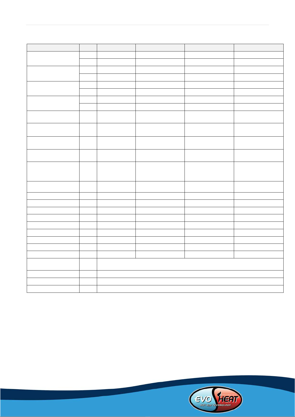
2.5 Specification Data
1. *Hot Water: outdoor temperature DB/WB20°C/15°C , outlet water circulation from 15°C to 55°C;
2. **Heating: outdoor temperature DB/WB7°C/6°C , outlet water 55°C, inlet water (return) 50°C;
3. ***Heating: outdoor temperature DB/WB7°C/°6C , outlet water 35°C, inlet water (return) 30°C;
4. Cooling: outdoor temperature DB/WB35°C/24°C , outlet water 7°C, inlet water (return) 12°C.
Evo Comfort Model
19
37
50
100
*Heating Capacity
kW
19.0
36.5
50
100
kcal/h
16337
31384
42992
85984
**Heating Capacity
kW
15.9
31.4
43
86.0
kcal/h
13672
26999
36973
73947
***Heating Capacity
kW
15.7
31.1
42
84.0
kcal/h
13500
26741
36114
72227
Cooling Capacity
kW
11.5
18.0
27.3
59.0
kcal/h
9888
15477
23473
46948
*Power Input for
Heating
kW
4.1
7.8
10.8
22.0
**Power Input for
Heating
kW
5.3
10.6
14.5
29.0
***Power Input for
Heating
kW
3.47
7.4
10
20.0
Power Input for
Cooling
kW
4.0
7.5
10.6
21.9
Running Current
(*Heating/**Heating/
***Heating/Cooling)
A
7.1/8.2/6.0/6.9
13.5/18.4/12.8/13.0
19.2/25.8/17.8/18.8
46.7/61.5/42.4/46.5
Power Supply
380-415V/3N~/50Hz 380-415V/3N~/50Hz 380-415V/3N~/50Hz 380-415V/3N~/50Hz
Compressor Quantity
1
2
1
2
Compressor Type
EVIScroll
EVIScroll
EVIScroll
EVIScroll
Fan Quantity
2
2
1
2
Fan Power Input
W
140x2
300x2
1100x1
1100x2
Fan Rotate Speed
RPM
850
875
900
900
Noise
dB(A)
60
65
68
73
Water Connection
inch
1
1.5
1.5
DN80 Flange
Water Flow Rate
M3/h
2.6
5.2
8.5
17
Water Pressure Drop
kPa
60
53
60
65
Unit Dimension
(L/W/H)
mm
(Subject to drawings of the heat pump)
Packing Size (L/W/H)
mm
(Subject to data on the package)
Net Weight
kg
(Subject to data on the nameplate)
Gross Weight
kg
(Subject to data on the package)
Page | 7
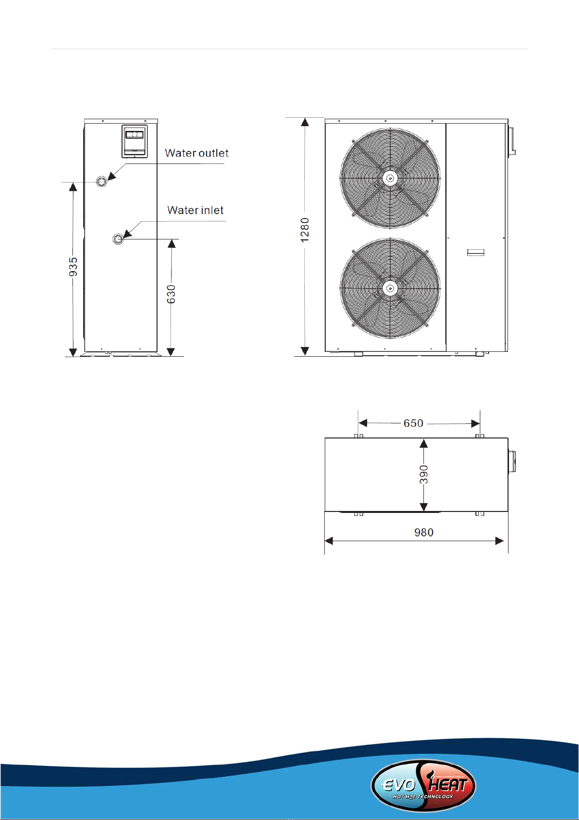
2.6 Unit Dimensions
Evo Comfort 19

Page | 8
Evo Comfort 37

Page | 9
Evo Comfort 50

Page | 10
Evo Comfort 100
Page | 11
3. Safety Precautions
To prevent personal injury and avoid causing damage to the unit, be sure to read the information
documented below.
The piping connection and wiring should be installed according to the local legislation and regulations as well
as the professional standard.
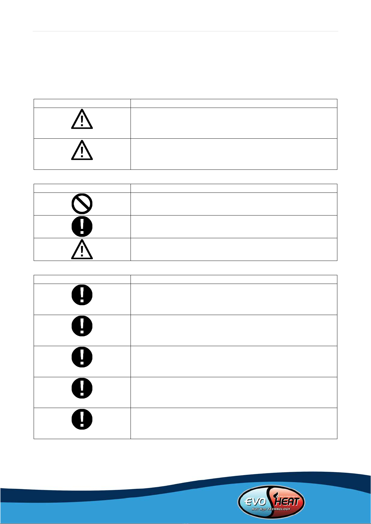
Mark
Meaning
WARNING
Wrong operation may lead to death or fatal injury on people.
ATTENTION
Wrong operation may lead to harm on people of loss of life.
Icon
Meaning
Prohibition. What is prohibited will be nearby this icon.
Compulsory implement. The listed action needs to be taken.
ATTENTION (including WARNING)
Please pay attention to what is indicated
Installation
Meaning
Professional installer is required
The heat pump must be installed by qualified personnel to avoid
improper installation which can lead to water leakage, electrical shock
or fire.
Earthing is required
Please make sure that the unit and power connection have good
earthing, otherwise this may cause electrical shock.
Installation Place
The unit CANNOT be installed near a flammable gas. Once there is any
leakage of the gas, fire can occur.
Fix the unit
Make sure that the basement of the heat pump is strong enough to
avoid any falling down of the unit.
Need circuit breaker
Make sure that there is circuit breaker for the unit, lack of circuit
breaker can lead to electrical shock or fire.
Page | 12
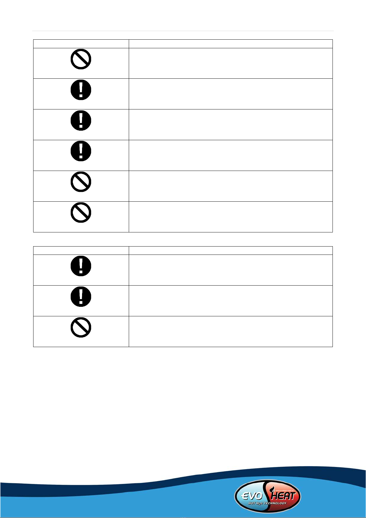
Operation
Meaning
PROHIBITION
DO NOT put fingers or objects into the fans and evaporator of the unit,
otherwise harm may occur.
Shut off the power
When there is something wrong or a strange smell, the power supply
needs to be shut off to stop the unit. Continuing to run may cause
electrical shortage or fire.
Check the installation basement
Please check the installation basement periodically (monthly), to avoid
any damage on the basement, which may hurt people or damage the
unit
Shut off the power
Please switch off the power for cleaning or maintenance.
Prohibition
It is prohibited to use copper or iron as fuse. The right fuse must be
fixed by an electrician for the heat pump.
Prohibition
It is prohibited to spray flammable gas near the heat pump as it may
cause fire.
Move and Repair
Meaning
Entrust
When the heat pump needs to be moved or installed again, please
entrust the dealer or qualified person to carry it out. Improper
installation will lead to water leakage, electrical shock, injury or fire.
Entrust
When the heat pump needs to be repaired, entrust the dealer or a
qualified person to carry it out. Improper movement or repair on the
unit will lead to water leakage, electrical shock, injury or fire.
Prohibit
It is prohibited to repair the unit by the user himself, otherwise
electrical shock or fire may occur.
Page | 13
4. Installation
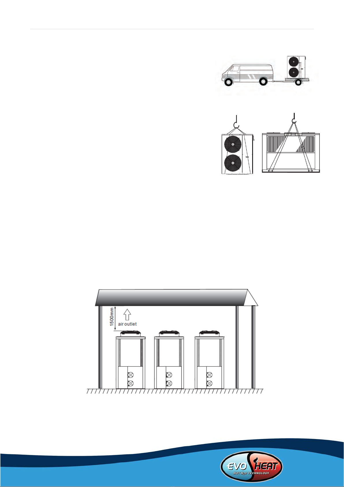
4.1 Transit
When the heat pump is to be transported, please keep the unit
standing upright. The unit cannot be laid down, otherwise inner
parts of the device may become damaged.
If the unit needs to be hung up during installation an 8 metre cable
will be needed to do so. There must be padding of some kind
between the cable and the unit to prevent damage to the heat
pump cabinet.
DO NOT TOUCH THE RADIATING FINS BEHIND THE MACHINE WITH
HANDS OR OBJECTS!
4.2 Installation Notes
-The unit can be installed in any outdoor area which can carry heavy machinery, such as a terrace,
rooftop, the ground etc.
-The location must have adequate ventilation and be free from strong winds.
-The installation location must be free from heat radiation and fire hazards.
-Ensure there are no obstacles near the air inlet and outlet of the heat pump.
-There must be a water channel around the heat pump to drain condensing water.
-Ensure that there is enough space around the unit for maintenance.
-The heat pump can be installed onto the concrete basement using expansion screws, or onto a steel
frame with rubber feet which can be placed on the ground or rooftop. Ensure the unit is placed
horizontally.
A snow shelter is required in areas that receive snow:

Page | 14
4.3 Water Loop Connection
•Try to reduce the resistance to the water from the piping.
•The piping must be clear and free from dirt and blockage. A water leakage test must be carried out to
ensure that there is no water leaking before the installation can be made.
•The pipe must be tested by pressure separately. DO NOT test it together with the unit.
•There must be an expansion tank on the top point of the water loop, and the water level inside the tank
must be at least 0.5meters higher than the top point of the water loop.
•The flow switch is installed inside of the heat pump, check to ensure that the wiring and action of the
switch is normal and controlled by the controller.
•The connection between the heat pump and the construction is best to be of a flexible type to avoid
vibration transfer. The support to the water pipe must be separate, but not rely on the heat pump unit.
•Try to avoid any air from being trapped inside the water pipe, there must be an air vent on the top point
of the water loop.
•There must be a thermometer and pressure meter at the water inlet and outlet for easy inspection
during running.
•There must be drainage on the low points of the water system, and there is already drainage on the
chassis of the heat pump. The water in the system must be drained out during winter if the heat pump is
not to be used.

Page | 15
4.4 Location of the Unit
This map only shows a single heat pump positioning.
ATTENTION
Requirement:
A>1500mm;
B>1000mm;
C>500mm;
D>1000mm.
The size of unit
Parallel model
L(mm)
W(mm)
H(mm)
Two units
2180
3160
2100
Three units
2180
5240
2100
Four units
2180
7320
2100
Five units
2180
9400
2100
The schematic diagram of installation
1
The place for maintenance more than 1500mm
2
The distance between two units more than 1500mm
3
The place for maintenance more than 1500mm
4
The place for maintenance more than 1500mm
5
The place for maintenance more than 1200mm
6
The distance between two units more than 1500mm

Page | 16
4.5 Water Connection Diagram
4.6 Power Supply Connection
-Open the front panel and open the power supply access.
-The power supply must go through the wire access and be connected to the power supply terminals in
the controlling box. Then connect the 3-signal wire plugs of the wire controller and main controller.
-If the outside water pump is needed, please inset the power supply wire into the wire access as well and
connect to the water pump terminals.
-If an additional auxiliary heater is needed to be to be controlled by the heat pump controller, the relay
(or power) of the aux-heather must be connected to the relevant output of the controller.

Page | 17
4.7 Cable and Switches
•The unit should use independent power supply, Wiring required by the corresponding table, Power
supply voltage must in line with rated voltage.
•Power supply circuit must be equipped with an All-pole disconnect device that has at least 3mm contact
opening distance.
•The wiring must be completed by professional technicians in accordance with circuit diagram.
•Power supply circuit must have earth wire, the earth wire of power should be connected with external
earth wire safely, and the external earth wire must be in order.
•The creepage protection device must be settled in accordance with the relevant national technical
standards for electronic equipment.
•The power wire and signal wire should be neatly arranged. High voltage wire and low voltage wires must
be separated and free from any interference, and they must be free from any piping and valves of the
unit.
•When all the wiring is completed, the power can only be connected after a double check.
Power Specifications
Unit Model
Power Supply
Cable
MCB
Creepage
Protector
Evo Comfort 19
380-415V/3N~50Hz
Section area
Earthing wire
40A
30mA less than
0.1 second
4x4mm2
2.5mm2
Evo Comfort 37
380-415V/3N~50Hz
Section area
Earthing wire
80A
30mA less than
0.1 second
5x16mm2
16mm2
Evo Comfort 50
380-415V/3N~50Hz
Section area
Earthing wire
80A
30mA less than
0.1 second
5x16mm2
16mm2
Evo Comfort
100
380-415V/3N~50Hz
Section area
Earthing wire
100A
30mA less than
0.1 second
25x4mm2
25mm2

Page | 18
4.8 Inspection Before Trial Operation
Check the indoor unit, make sure that the pipe connection is done correctly and that the relevant valves are
open.
Check the water loop to ensure that there is enough water inside of the expansion tank, that the water
supply is good and that the water loop has no air in it and is full of water. Make sure there in good insulation
for the water pipe.
Check the electrical wiring. Make sure that the power voltage is normal, the screws are fastened, the wiring
is made in line with the diagram and the earthing is connected.
Check that the heat pump, including all the screws and different parts are in good order. When the power is
on, review the indicator on the controller to see if there are any failure indications. The gas gauge can be
connected to the check valve to see the high pressure (or low pressure) of the system during trial running.
4.9 Trial Operation
Start the heat pump by pressing the ‘Power Button’ key on the controller. Check whether the water pump is
running, if it is running normally there will be 0.2MPa on the water pressure meter.
When the water pump runs for 1 minute, the compressor will start. Hear whether there is a strange sound
coming from the compressor. If an abnormal sound occurs, please stop the unit and check the compressor. If
the compressor runs well, look for the pressure meter of the refrigerant.
Check whether the power input and running current is in line with the manual. If not stop the unit and check
for why this may be occurring.
Adjust the valves on the water loop to make sure that the hot (cool) water supply to each door is good and
meets the requirement of heating (or cooling).
Review whether the outlet water temperature is stable.
The parameters of the controller are set by the factory, the user must not change these.
Page | 19
5. Controlling and Operation
5.1 Main Interface Display and Function
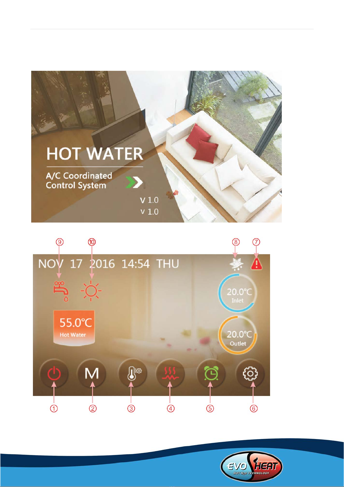
5.1.1 Power On Screen
5.1.2 Start Up Screen

Page | 20
Key Functions
Key No.
Key Name
Key Function
1
On and off
Click this key to switch ON or OFF
Red represents ON, while grey represents OFF
2
Mode key
Hot water mode, heating mode, cooling mode, hot water + heating
mode or hot water + cooling mode can be selected by pressing this key
3
Temperature setting
Click this to set the target temperature
4
Fast heating
Click this key to start rapid heating
This key will be displayed during heating
5
Timer setting
Click this key to set the timer. White represents not enabled, while
green represents enabled
6
Setup key
Click this key to check the unit status, time, factory parameters,
temperature curve, timer setting and mute setting
7
Fault icon
This icon will flash when there is an error occurring, then the display
will enter the failure record interface after tapping this icon
Note:
8is the defrosting icon, the machine is in defrosting mode when this icon is shown
9is the hot water mode icon, this machine is in hot water mode then this icon is shown
10 is the heating mode icon, this machine is in heating mode when this icon is displayed
This manual suits for next models
4
Table of contents
Other evoheat Heater manuals


Popular Heater manuals by other brands


MV Heating
MV Heating MV Airo 2 instruction manual

Honeywell
Honeywell COMFORTTEMP 4 HCE640 Series manual

Linea 2000
Linea 2000 DOMO DO7338H Instruction booklet

Dimplex
Dimplex EPX 500 Installation and operating instructions

Silvercrest
Silvercrest SKD 2300 B2 operating instructions

ARDES
ARDES AR4C05 Instructions for use