Evolution L Series User manual

LITHIUM-ION BATTERY MANUAL
LANCE.LIAN
v1.0
@ALL RIGHTS RESERVED BY EVOLUTION ELECTRIC VEHICLES

CONTENT
Table Of Contents
.Lithium iron phosphate battery.....................................................9
3.Introduction.................................................................................9
.Flooded battery vs lithium-ion battery............................................4
.How does a lithium-ion battery work..............................................5
.Guide to understanding battery specifications................................6
1.Safety Precautions............................................................. ..........1
.Lithium-ion battery......................................................................3
2.LFP battery technology basics.......................................................3
. Installation prerequisites............................................................16
4.Lithium Battery System...............................................................10
.6.2 Evolution LEP battery pack system design..............................14
.6.1 Inside battery........................................................................13
.4.1 Evolution LEP battery pack system........................................10
5.Lithium Battery Models................................................................11
.6.3System design......................................................................15
7.Battery Installation/Commissioning..............................................16
6.Battery Structure ........................................................................13
.Battery storage(shelf storage life span)......................................30
.Where to recycle or safely dispose batteries................................32
11.Battery Storage .......................................................................30
.D a i ly ch e c k.. . . .. . . .. . . ... . ... . . .. . . .. . . ... . ... . . .. . . .. . . ... . ... . . .. . . .. . . .33
12.Battery Disposal .......................................................................32
13.Battery Maintenance Checklist..................................................33
.Monthly check................................................................33
.Maintenance checklist..............................................................33
.Proper storage(installed in vehicle)...........................................31
.Annu al check........ ........... ................ ........... ............ ......33
14. Battery Warranty Terms............................................................34
9.Battery Charging and Discharging ...............................................22
. System connection....................................................................17
.Charging...................................................................................22
10. Battery Troubleshooting............................................................25
.Essential service tools................................................................25
.BBMS app connection issues......................................................25
.Battery issues............................................................................25
.Cell balancing............................................................................22
.BMS issues...............................................................................27
.Battery pack troubleshooting.......................................................28
. Safety gear...............................................................................16
. BBMS mobile app......................................................................20
8.Battery Operation.......................................................................20
.Disharging.................................................................................24
.Charging...................................................................................23
. Installation /Commissioning requirement.....................................18
. Tools........................................................................................16
. Monitoring................................................................................20

1
SAFETY PRECAUTIONS
1.Safety Precautions
1.1General Warnings
1.2Charge and Discharge Warnings
Observe these instructions and keep them located near the battery for future
reference.
The Material Safety Datasheet can be downloaded from the “Material Safety
Datasheet menu”.
Work on a li-ion battery should be carried out by qualified personnel only.
While working on a li-ion battery wear protective eyeglasses and clothing.
Any uncovered battery material such as electrolyte or powder on the skin or
in the eyes must immediately be flushed with plenty of clean water. Then seek
medical assistance. Spillages on clothing should be rinsed out with water.
Explosion and fire hazard. The terminals of a li-ion battery are always live, therefore do not
place metallic items ortools on top of a li-ion battery. Avoid short circuits, too deep
discharges and too high charge currents. Use insulated tools. Do not wear any metallic
items such as watches, bracelets, et cetera. In case of fire, you must use a type D foam or
CO2 fire extinguisher.
Do not open or dismantle the battery. Electrolyte is very corrosive. In normal working
conditions contact with the electrolyte is impossible. If the battery casing is damaged do not
touch the exposed electrolyte or powder because it is corrosive.
Li-ion batteries are heavy. If involved in an accident they can become a
projectile! Ensure adequate and secure mounting and always use suitable
handling equipment for transportation.
Handle with care because a li-ion battery is sensitive to mechanical shock.
Do not use a damaged battery.
Do not wet the battery.
Too deep discharges will seriously damage a li-ion battery and can even be
dangerous. Therefore, use of an external safety relay is obligatory.
Use only with a EVOLUTION approved BMS.
If charged after the Lithium Battery was discharged below the “Discharge cut
-off voltage”, or when the Lithium Battery is damaged or overcharged, the
Lithium Battery can release a harmful mixture of gasses such as phosphate.
The temperature range over which the battery can be charged is 0°C to 45°C.
Charging the battery at temperatures outside this range may cause severe
damage to the battery or reduce battery life expectancy.

2
SAFETY PRECAUTIONS
1.3Transportation Warnings
1.4Disposal of lithium batteries
The temperature range over which the battery can be discharged is -20°C to
50°C. Discharging the battery at temperatures outside this range may cause
severe damage to the battery or reduce battery life expectancy.
The battery must be transported in its original or equivalent package and in
an upright position. If the battery is in its package, use soft slings to avoid
damage.
Do not stand below a battery when it is hoisted.
Never lift the battery at the terminals or the BMS communication cables, only
lift the battery at the handles.
Batteries are tested according to UN Handbook of Tests and Criteria, part III, sub
section 38.3 (ST/SG/AC.10/11/Rev.5).
For transport the batteries belong to the category UN3480, Class 9, Packaging
Group II and have to be transported according to this regulation. This means that for
land and sea transport (ADR, RID & IMDG) they have to be packed according
to packaging instruction P903 and for air transport (IATA) according to packaging
instruction P965. The original packaging complies with these instructions.
Batteries marked with the recycling symbol must be processed via a
recognized recycling agency. By agreement,they may be returned to the
manufacturer.
Batteries must not be mixed with domestic or industrial waste .
Do not throw a battery into fire.

3
lfp battery basics
2.LFP battery technology basics
2.1 Lithium-ion battery
ŸNickel-metal-hydride (NiMH) - have a higher energy density compared to nickel
cadmium at the expense of reduced cycle life. Contain no toxic metals.
ŸLead-acid (vented & valve-regulated) batteries .Most economical for larger power
applications where weight is of little concern.
Lithium-ion (lithium-ion) batteries are projected to become the most popular battery
forfull-battery electric vehicles.Compared with other relevant battery types, lithium-
ion batteries have the highest power density.
ŸNickel-cadmium (NiCd) (vented & semi-sealed) - mature but have moderate
energy density. Nickel-cadmium batteries have generally been used where long
life, high discharge rate and extended temperature range is important. Nickel-
cadmium batteries contain toxic metals and are generally being phased out.
A battery is a device that converts chemical energy into electrical energy and vice
versa.The battery categories can be broken down by the chemistries used in the
construction of the battery.
ŸLithium-ion (Li-ion)- fastest growing battery technology offering high energy
density and low weight. Requires protection circuits to limit voltage and current
for safety reasons.
Figure1

4
lfp battery basics
>Flooded Lead acid batteries, as the name suggests, have plates that are immersed in an acid
electrolyte.Since they are not sealed, the hydrogen generated during operation escapes directly into
the environment, meaning that ventilation systems must be more powerful than those for VRLA and,
so,sized adequately . Flooded batteries must be kept and operated upright, and their water levels
must be manually topped up. They provide a longer life span and higher reliability than sealed lead
acid batteries, but not as high as lithium batteries.
Flooded batteries VS Lithium- ion battery?
>Lithium-ion batteries are the most suitable existing technology for electric vehicles because they
can output high energy and power per unit of battery mass, allowing them to be lighter and smaller
than other rechargeable batteries .These features also explain why lithiumion batteries are already
widely used for consumer electronics such as cell phones, laptop computers, digital cameras/video
cameras, and portable audio/game players. Other advantages of lithium-ion batteries compared to
lead acid and nickel metal hydride batteries include high-energy efficiency, no memory effects, and a
relatively longer cycle life
Lithium-ion batteries
A common way to distinguish the main different types of lithium-ion batteries is to consider the
cathode composition. The choice of battery depends on various factors, including cell voltage,
capacity, energy and power capabilities, cycle life, and temperature of operation.
Various LIB chemistries exist, which can be simplified into six main types based on the composition of
the cathode material (items 1 to 5) or anode material (item 6):
In a lithium-ion battery (LIB), the "cathode" is usually made of a metal oxide, while the anode is
usually porous carbon graphite. Both are immersed in a liquid electrolyte made of lithium salt and or
ganic solvent. During discharge, the ions flow from the anode to the cathode through the electrolyte
and separator; charging reverses the direction, and the ions flow from the cathode to the anode.
2. Lithium manganese oxide (LMO)
3. Lithium-nickel manganese cobalt oxide (NMC)
5. Nickel cobalt alumina (NCA)
6. Lithium titanium oxide (LTO)
1. Lithium cobalt oxide (LCO)
It is not possible to compare these different families precisely, since many aspects other than
technology play an important role in performance, such as mechanical form, cell size and active
material mix. Different battery manufacturers also combine technologies to improve performance for
a specific application.
4. Lithium iron phosphate (LFP)

5
lfp battery basics
How does a lithium-ion battery work?
A lithium-ion battery is a rechargeable battery in which lithium ions move between
the anode and cathode, creating electricity flow useful for electronic applications. In
the discharge cycle,lithium in the anode (carbon material) is ionized and emitted to
the electrolyte. Lithium ions move through a porous plastic separator and insert into
atomic-sized holes in the cathode (lithium metal oxide). At the same time, electrons
are released from the anode. This becomes electric current traveling to an outside
electric circuit. When charging, lithium ions go from the cathode to the anode
through the separator. Since this is a reversible chemical reaction, the battery can
be recharged .
LiCoO2+ C → Li1–xCoO2+ LixC
Subsequent discharge reactions occur through the migration of lithium
ions from the anode to the cathode.
By means of the initial charging, which takes place during battery
manufacture, lithium ions migrate from the lithium compound of the
cathode to the carbon material of the anode.
More specifically, during charging lithium is dedoped from cathodes
consisting of a lithium-containing compound, and the interlayers of
carbon in anodes are doped with lithium. Conversely, during discharge
lithium is dedoped from between the carbon layers in anodes, and the
compound layers in cathodes are doped with lithium. Reactions
o c c u r r i n g i n l i t h i u m i o n r e c h a r g e a b l e b a t t e r i e s e m p l o y i n g
LiCoO2(lithium cobaltate) in cathodes and carbon in anodes are shown
in Figure1.
Battery charging and discharging occur through the migration of lithium
ions between the cathodes and anodes and the exchange of electrons
through doping and dedoping.
Charge/discharge mechanism.
Initial charge
charge
Li1–xCoO2+ LixC Li1–x+dxCoO2+ Lix–dxC
discharge
A lithium-ion battery cell contains four main components: cathode,
anode, electrolyte and separator . Lithium-ion battery cells are sold in “battery
packs,” which include battery management systems (BMS) . For Evolution lithium
battery pack it contains 16 cells in each pack ,connected in series circuit .BMS
system is integrated inside of battery packs.

6
lfp battery basics
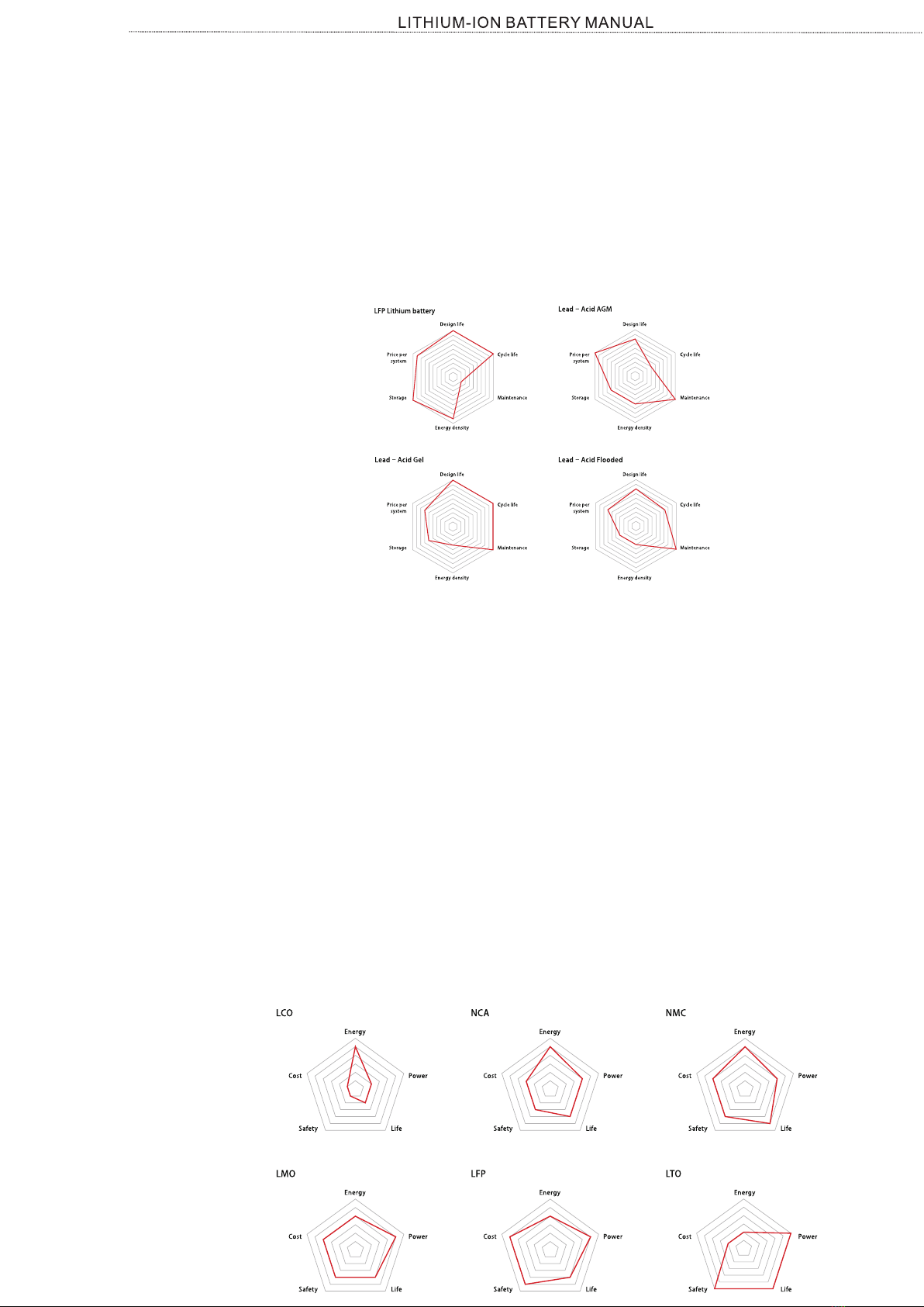
ŸBattery Classifications – Not all batteries are created equal, even batteries of
the same chemistry. The main trade-off in battery development is between power
and energy: batteries can be either high-power or high-energy, but not both.
Often manufacturers will classify batteries using these categories. Other
common classifications are High Durability, meaning that the chemistry has been
modified to provide higher battery life at the expense of power and energy.
ŸC- and E- rates – In describing batteries, discharge current is often expressed as
a C-rate in order to normalize against battery capacity, which is often very
different between batteries. a C-rate is a measure of the rate at which a battery is
discharged relative to its maximum capacity. a 1C rate means that the discharge
current will discharge the entire battery in 1 hour. For a battery with a capacity of
100 Amp-hrs, this equates to a discharge current of 100 Amps. A 5C rate for this
battery would be 500 Amps, and a C/2 rate would be 50Amps. Similarly, an E-rate
describes the discharge power. A 1E rate is the discharge power to discharge the
entire battery in 1 hour.
Battery Basics
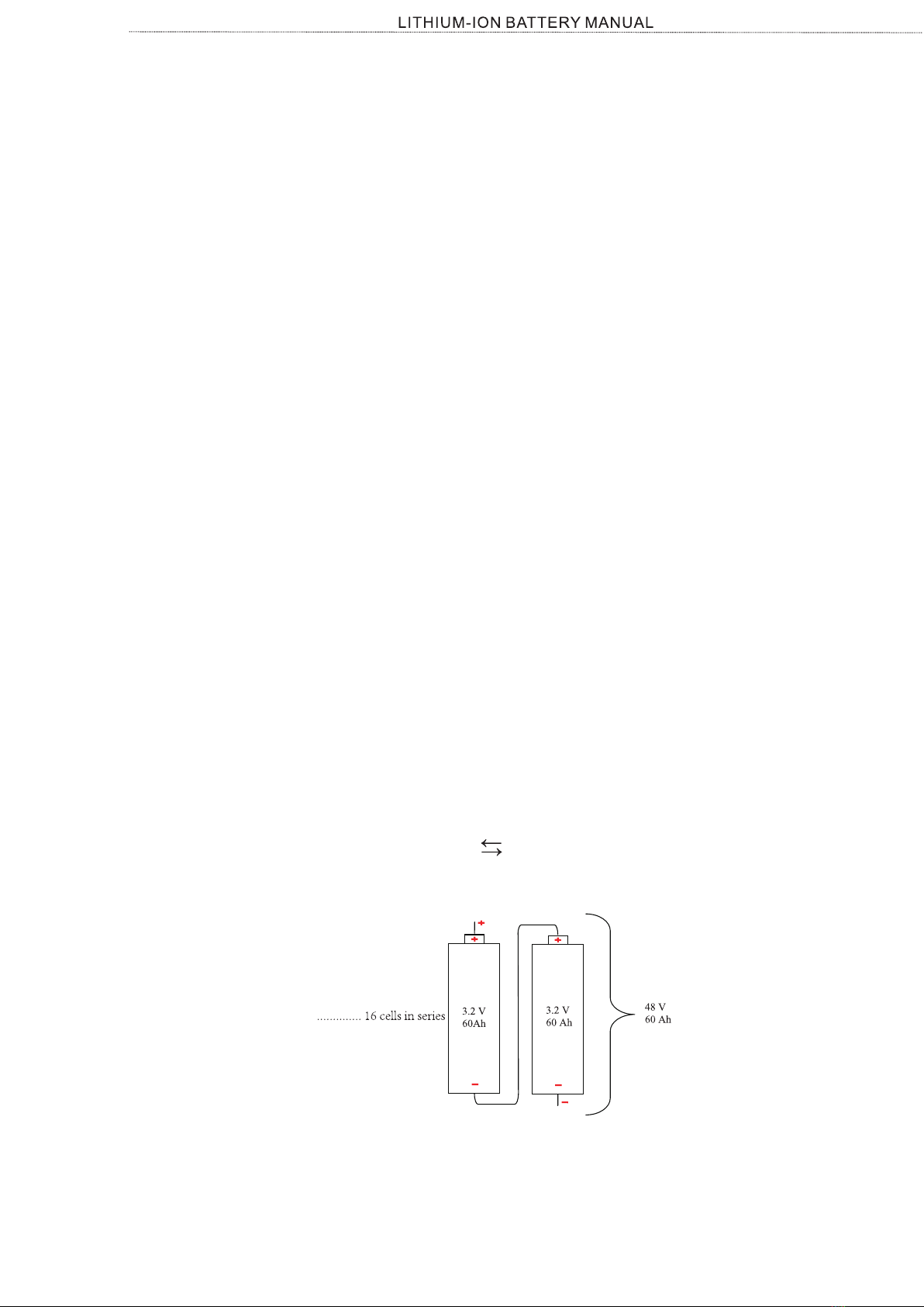
ŸCell, modules, and packs – Electric vehicles have a high voltage battery pack
that consists of individual modules and cells organized in series and parallel. A
cell is the smallest, packaged form a battery can take and is generally on the
order of one to six volts. A module consists of several cells generally connected
in either series or parallel. A battery pack is then assembled by connecting
modules together, again either in series or parallel.
A battery is a device that converts chemical energy into electrical energy and vice
versa. This summary provides an introduction to the terminology used to describe,
classify, and compare batteries for electric vehicles. It provides a basic
background, defines the variables used to characterize battery operating
conditions, and describes the manufacturer specifications used to characterize
battery nominal and maximum characteristics.
Guide to Understanding Battery Specifications
This section describes some of the variables used to describe the present condition
of a battery.
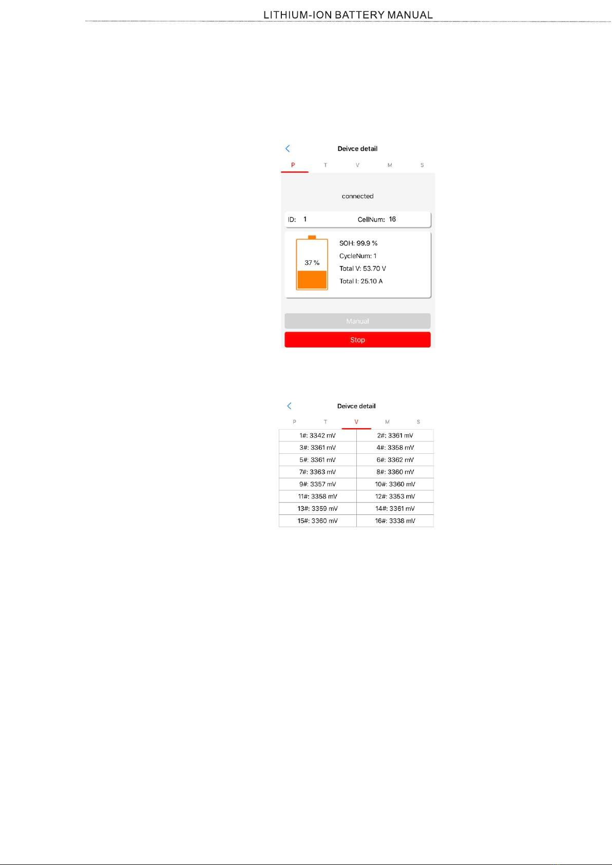
ŸState of Charge (SOC)(%) – An expression of the present battery capacity as a
percentage of maximum capacity. SOC is generally calculated using current
integration to determine the change in battery capacity over time.
Battery Condition
ŸOpen-circuit voltage (V) – The voltage between the battery terminals with no
load applied. The open-circuit voltage depends on the battery state of charge,
increasing with state of charge.
ŸState of Health (SOH)(%) – An expression of the present battery Health(Life
expection/Capacity) as a percentage of maximum life span. SOH is generally
calculated using current/voltage/cell resistance integration to determine the
change in battery life span expectation over time.
ŸDepth of Discharge (DOD) (%) – The percentage of battery capacity that has
been discharged expressed as a percentage of maximum capacity. A discharge
to at least 80 % DOD is referred to as a deep discharge.
ŸInternal Resistance – The resistance within the battery, generally different for
charging and discharging, also dependent on the battery state of charge. As
internal resistance increases, the battery efficiency decreases and thermal
stability is reduced as more of thecharging energy is converted into heat.
ŸTerminal Voltage (V) – The voltage between the battery terminals with load
applied.Terminal voltage varies with SOC and discharge/charge current.

7
lfp battery basics
ŸCharge Voltage – The voltage that the battery is charged to when charged to full
capacity. Charging schemes generally consist of a constant current charging until
the battery voltage reaching the charge voltage, then constant voltage charging,
allowing the charge current to taper until it is very small.
ŸNominal Voltage (V) – The reported or reference voltage of the battery, also
sometimes thought of as the “normal” voltage of the battery.
Battery Technical Specifications
ŸCycle Life (number for a specific DOD) – The number of discharge-charge
cycles the battery can experience before it fails to meet specific performance
criteria. Cycle life is estimated for specific charge and discharge conditions. The
actual operating life of the battery is affected by the rate and depth of cycles and
by other conditions such as temperature and humidity. The higher the DOD, the
lower the cycle life
ŸEnergy or Nominal Energy (Wh (for a specific C-rate)) – The “energy capacity”
of the battery, the total Watt-hours available when the battery is discharged at a
certain discharge current (specified as a C-rate) from 100 percent state-of-
charge to the cut-off voltage. Energy is calculated by multiplying the discharge
power (in Watts) by the discharge time (in hours). Like capacity, energy
decreases with increasing C-rate.
ŸMaximum Continuous Discharge Current – The maximum current at which the
battery can be discharged continuously. This limit is usually defined by the
battery manufacturer in order to prevent excessive discharge rates that would
damage the battery or reduce its capacity. Along with the maximum continuous
power of the motor, this defines the top sustainable speed and acceleration of the
vehicle.
ŸCut-off Voltage – The minimum allowable voltage. It is this voltage that generally
defines the “empty” state of the battery.
ŸSpecific Energy (Wh/kg) – The nominal battery energy per unit mass,
sometimes referred to as the gravimetric energy density. Specific energy is a
characteristic of the battery chemistry and packaging. Along with the energy
consumption of the vehicle, it determines the battery weight required to achieve
a given electric range.
ŸFloat Voltage – The voltage at which the battery is maintained after being charge
to 100percent SOC to maintain that capacity by compensating for self-discharge
of the battery
ŸCapacity or Nominal Capacity (Ah for a specific C-rate) – The coulometric
capacity, the total Amp-hours available when the battery is discharged at a
certain discharge current (specified as a C-rate) from 100 percent state-of-
charge to the cut-off voltage. Capacity is calculated by multiplying the discharge
current (in Amps) by the discharge time (in hours) and decreases with increasing
C-rate.
ŸMaximum 30-sec Discharge Pulse Current –The maximum current at which the
battery can be discharged for pulses of up to 30 seconds. This limit is usually
defined by the battery manufacturer in order to prevent excessive discharge
rates that would damage the battery or reduce its capacity. Along with the peak
power of the electric motor, this defines the acceleration performance (0-25 mph
time) of the vehicle.
This section explains the specifications you may see on battery technical
specification sheets used to describe battery cells, modules, and packs.

8
lfp battery basics
Ÿ(Recommended) Charge Current – The ideal current at which the
battery is initially charged (to roughly 70 percent SOC) under
constant charging scheme before transitioning into constant voltage
charging.
Ÿ(Maximum) Internal Resistance – The resistance within the battery,
generally different for charging and discharging.
.Battery specifications display example with from Evolution battery pack -1.
.Battery specifications display example with from Evolution battery pack-2.

9
As part of the protection the battery has an integrated Balancing, Temperature and
Voltage control system. The Battery Management System, the BMS monitors each
individual battery cell; it balances the cell voltages and in case of high or low cell
voltage or in case of high or low cell temperature, it will generate an alarm signal.
The alarm signal is received by the BMS and the BMS will turn off loads or chargers
accordingly.
The battery cells in the Smart Lithium batteries are protected against over-charge,
under-charge, charging at too low temperatures as well as charging at too high
temperatures.
A BMS is essential for a correct operation of the lithium battery. The lithium battery
is not allowed to be used without one. In addition to this you will also need to ensure
that the BMS correctly controls all loads and charge sources that are connected to
the battery.
Introduction
3.Introduction
3.1Lithium iron phosphate battery
The lithium iron phosphate battery is therefore the chemistry of choice for a range of
very demanding applications.
The lithium iron phosphate battery (LiFePO4 or LFP) is the safest of the mainstream
lithium battery types. A single LFP cell has a nominal voltage of 3.2V. A 48 V LFP
battery consists of 16 cells connected in series.
LFP is the chemistry of choice for very demanding applications. Some of its features
are:
• High round trip efficiency.
• High energy density - More capacity with less weight and volume.
• Rugged - It can operate in deficit mode during long periods of time.
• High charge and discharge currents - Fast charge and discharges are possible.
• Flexible charge voltages.
3.2Lithium battery models
• LiFePO4 Battery 48V/130Ah .
• LiFePO4 Battery 48V/110Ah .
• LiFePO4 Battery 48V/180Ah .
The Lithium Smart Battery is available in a variety of capacities and with same
voltages, namely 48V. These are all available battery models:
• LiFePO4 Battery 48V/60Ah .
3.3Battery Management System(BMS)
3.4Battery app connect
The battery is equipped with Bluetooth and uses this to communicate with the BBMS
app. The BBMS app is used for reading out battery information, for making or
changing battery settings, receiving alarms .,etc.

10
lITHIUM BATTERY SYSTEM
4.Lithium Battery System
4.1Evolution LFP battery pack system
Grab Handles Aluminum Cover With
Water-Resistant Gasket
Aluminum Casing
S/W Switch Battery Terminal
B+ Docking Feet
Battery terminals
B-
RS 485 Com-port
Battery Indicator

11
lITHIUM BATTEY MODELS
5.Lithium Battery Models

12
lITHIUM BATTEY MODELS

13
Battery sTRUCTURE
6.Battery Structure
6.1 Inside battery
(8 Cells in series connection)
Battery Cell Module 1
Battery Cell Module 2
(8 Cells in series connection)
(BMS PCB)
Battery Management System
48VDC Solenoid
Diverter
Pre-charge Resistor
Battery Cell Module 1 and Module 2 are connected in series.
A battery has 2 cell modules in total 16 cells in series connections.
Battery Pack
Battery Pack
BATTERY INTERNAL COMPONENT LAYOUT
BATTERY INTERNAL CIRCUIT DIAGRAM

14
6.2Evolution LFP battery pack system design
.Diverter
Signal outlet for BDI display(battery SOC indicator) module.
Allow user to manually switch on the battery.
.Rs485 service port
Each Battery has 16 cells ,each cell is 3.2V (nominal voltage),16 cells are connected in series circuit.
A solenoid is a set of coiled wire which acts as an electromagnet when current is passed through it. It
converts electrical energy directly into linear mechanical motion. Works as switch controls On/Off of
circuit .
A temperature sensor is a device that is designed to measure the degree of hotness or coolness in an
object. The working of a temperature meter depends upon the voltage across the diode. The
temperature change is directly proportional to the diode’s resistance. The cooler the temperature,
lesser will be the resistance, and vice-versa.The resistance across the diode is measured and
converted into readable units of temperature (Fahrenheit, Celsius, Centigrade, etc.) .
Each Battery has 6 temperature sensor probes >
1 sensor probe on solenoid .
1 sensor probe on BMS circuit board .
.Solenoid
.Battery Cells
4 sensor probes in between battery cells .
.Temperature Sensor Probes
The battery cells in the Smart Lithium batteries are protected against over-charge, under-charge,
charging at too low temperatures as well as charging at too high temperatures.As part of the
protection the battery has an integrated Balancing, Temperature and Voltage control system. The
Battery Management System, the BMS monitors each individual battery cell; it balances the cell
voltages and in case of high or low cell voltage or in case of high or low cell temperature, it will
generate an alarm signal. The alarm signal is received by the BMS and the BMS will turn off loads or
chargers accordingly.A BMS is essential for a correct operation of the lithium battery. The lithium
battery is not allowed to be used without one. In addition to this you will also need to ensure that the
BMS correctly controls all loads and charge sources that are connected to the battery.
.Battery Management System(BMS)Control Board
.S/W switch button
Capture & Sample real-time battery pack voltage and current values
.Pre-Charge Resistor
A pre-charge resistor is a device that slowly charges the capacitors inside a electronic circuit
board(in this battery case it is for battery BMS board) before it is powered up. Without this resistor,
closing the contactor would generate a large amount of inrush current causing the contacts to arc.
This arcing can permanently weld the contacts in the "on" position.
Battery sTRUCTURE

15
6.3System design
• Low temperature signal
When designing a system with a lithium battery, a basic understanding of how the
battery interacts with the BMS and how the BMS interacts with loads and chargers is
required.
.The Battery Cell Alarm Signal
The battery communicates with the BMS Control PCB board via its BMS cable harness.
The battery monitors its cells and it will send an alarm signal to the BMS in case of a:
• Low cell voltage alarm signal
• Low cell voltage pre-alarm signal
• High cell voltage signal
.Battery monitoring
>In the event of low cell voltage, the BMS will send a “load disconnect” signal to turn the load(s) off.
The BBMS App is needed to communicate with the battery. The app can run on an Android, iOS or
macOS device. Although there also is a Windows version of the app, it is not possible to use the
Windows version of the BBMS App for the Smart Lithium batteries, as Windows Bluetooth is not
supported by the BBMS App.
.Update the battery BMS firmware
.How BMS controls system On/Off ?
.Download and install the APP
The BMS is equipped with a “load disconnect”, a “charge disconnect”alarm contact .The BMS sends
a “load disconnect” signal to loads in case of a low cell voltage alarm and it sends a “charge
disconnect” signal to chargers in case of a high cell voltage or a cell temperature alarm. The loads or
chargers can be controlled by the BMS directly .
The BMS will act by turning loads and/or chargers off as soon it receives an alarm signal from one
of the cells in the battery.
The battery internals (temperature & cell voltages, as well as alarms and other parameters) can be
monitored with the BBMS App. It connects to the battery via Bluetooth.
Firmware for BMS PCB board can be updated in case there may be bugs or upgrades the firmware
can be renewed with Specified tool(Firware downloader) , Consider this tool as essential service tool
for servicing batteries .
>In the event of high cell voltage or low or high cell temperature, BMS will send a “charge disconnect”
signal to turn the charger(s) off.
The main purpose of the BMS is to control the chargers and the loads. This is the way how Evolution
battery do that:
• High temperature signal
. By physically connecting or disconnecting a load or a charge source from the battery, using a large
contactor (48V solenoid).
Battery sTRUCTURE

16
Battery Installation/Commissioning
7.Battery Installation/Commissioning
When installing the system, avoid touching the battery terminal with any metal
objects or human body. Evolution EV provides a safe source of electric energy when
operated as designed. Potentially hazardous circumstances such as excessive heat
or electrolyte leakage may occur under improper operating conditions, damage,
misuse and abuse. The safety precautions and the warning messages described in
section 1 must be observed. If any of the precautions are not fully understood, or if
you have any questions,contact customer service for guidance. The Safety Section
may not include all regulations for your region.
Make sure that the battery installation to vehicle meets the following conditions:
>There are no flammable or explosive materials nearby
>The ambience is shady and cool, keep away from heat and avoid direct
>The battery installation position is flat and level
sunlight.
>The temperature and humidity stays at a constant level.
>There is minimal dust and dirt in the area.
>There is no corrosive gases present, including ammonia and acid vapor.
Warning
If the ambient temperature exceed the operating range, the battery module stops
operating to protect itself. The optimal temperature range for the battery module to
operate is 0°C to 45°C (when temperature is lower than 0°C,heating system is
requested in order to allow battery to be functional ). Frequent exposure to harsh
temperatures may deteriorate the performance and life time of the battery module.
7.1Installation Prerequisites
7.2 safety gear
circuit and personal injury.
Installation and maintenance personnel must operate according to applicable
federal, state and local regulations as well as the industry standards regarding the
product installation personnel shall wear safety gears, etc. in order to avoid short
7.3 Tools
These tools are required to install the Evolution EV battery system..
>When connecting battery cables, pay particular attention to the polarity of the battery terminals.
Never confuse the positive and negative cables.
>If repairs are to be made that will require welding or cutting, the batteries must be removed.
>Always turn the key switch to ‘OFF’ and remove the key before disconnecting a live circuit.
Insulated Gloves Safety Goggles
Insulated Gloves Safety Shoes
Screwdriver
Torque
Screwdriver
Phillips-head
Screwdriver
Flat-head Insulated
Wrench
Torque Screwdriver Drill Pencil or Marker Pen Tape
Measure

17
Battery Installation/Commissioning
7.4.1 Check for Transport Damage
Make sure the battery is intact during transportation. If there are some visible
damages, such as cracks, please contact your dealer immediately.
7.4.2 Unpacking
Unpacking the battery package by cutting the packing tape and make sure
theBattery modules and the relevant items are complete. See package items on the
manual inside the battery package, please check the packing list carefully, if there's
any item missing, please contact Evolution EV or your distributer directly.
7.4 System Connection
.Batteries are heavy. Use proper lifting techniques when moving them. Always
lift the battery with a commercially available battery lifting device. Use care
not to tip batteries excessively when removing or installing them;
.Wear Insulated gloves and Wrap wrenches with vinyl tape to prevent the
possibility of a dropped wrench ’shorting out’ a battery,which could result in an
explosion and severe personal injury or death.
.Adaptive Installation Brackets & Hardwares
.Battery Pack
.Charger & Charger Hardwares
.Battery Indication Gauge
.Peripheral accessories
7.4 Pre-installation inspection
According to regional regulations, several people may be required for moving
equipment.
Please strictly follow the installation steps. Evolution EV will not answer for any
hurting or loss arising by incorrectly assembling and operation.
7.5 Installation
THE BATTERY PACK IS SUITABLE FOR ALL TOP BRAND GOLF CARTS. IN
ORDER TO PROPERLY INSTALL THE BATTERY , EACH PACKAGES HAS ITS
OWN MANUAL
>Follow the manual packed inside battery package for specific steps to install
battery on specific brands / models .

18
Battery Installation/Commissioning
.Mounting
The battery needs to be mounted in an upright position. The battery is only suitable for electric
vehicle use and needs to be located in a specified location/Compartment.
>Batteries are heavy. When moving the battery into its destined location, use suitable handling
equipment for transportation.
.Connect the battery poles
The positive pole is indicated by a “+” symbol and the negative pole is indicated by a “-“ symbol.
>Observe the battery polarity when connecting the battery poles to a vehicle system or to other
batteries. Take care not to short circuit the battery poles.
>Batteries produce a certain amount of heat when they are charged or discharged. Keep a 20mm
space on each side of the battery for ventilation purposes.
>Connect the cables; place the cable’s cable lug on the battery pole, place the washer, place the
spring washer and then insert and tighten the bolt
>Ensure adequate and secure mounting as the battery can become a projectile if involved in an
accident.
>When tightening the bolt, use the correct torque and use insulated tools that match the batteries
spanner size
Use battery cables match the currents that can be expected in the battery system. Batteries can
produce very large currents; it is therefore necessary that all electrical connections to a battery
match the expected maximum system currents.
..Cables used to connect batteries
>The battery maximum discharge rating is indicated in below table.
Battery Model Nut Size Torque Moment
51.2V 60AH M6 10NM
51.2V 110AH M8 12NM
51.2V 130AH M8 12NM
51.2V 180AH M8 12NM
Maximum Current Rating Lithium Battery
Battery Model Maximum current rating
(Peak Current @30s)
51.2V 60AH 180A
51.2V 110AH 330A
51.2V 130AH 400A
51.2V 180AH 400A
If the battery is located far away for cables to reach ,use optimal cables to
avoid voltage dropping/cable melting ;etc .
7.5.1 Installation /Commissioning Requirement
This manual suits for next models
4
Table of contents
Other Evolution Camera Accessories manuals