Ewellix Telesmart TXG Series User manual

CATEGORY
MAX 2 LINESINSTALLATION, OPERATION AND MAINTENANCE MANUAL
Telesmart TXG
Telescopic pillar


33
Contents
1.0 General information......................................................4
1.1 Information in this manual ...............................................4
1.2 Explanation of symbols and signal words ......................4
1.3 Limitation of liability ........................................................5
1.4 Copyright.........................................................................5
1.5 Spare parts......................................................................5
1.6 Warranty terms................................................................5
1.7 Customer service ............................................................5
2.0 Safety .............................................................................6
2.1 Use ...................................................................................6
2.1.1 Intend ed use ..............................................................6
2.1.2 Unintended Use ........................................................6
2.1.3 Essential performance ..............................................6
2.2 Responsibility of the owner and processor....................6
2.3 Personnel requirements..................................................7
2.3.1 Qualications ............................................................7
2.4 Specic dangers .............................................................7
2.5 Safety equipment ............................................................7
2.6 Safeguard against restart ...............................................8
2.7 Modications of device ...................................................8
2.7.1 Warning labels ...........................................................8
3.0 Technical data...............................................................9
3.1 Ambient conditions .........................................................9
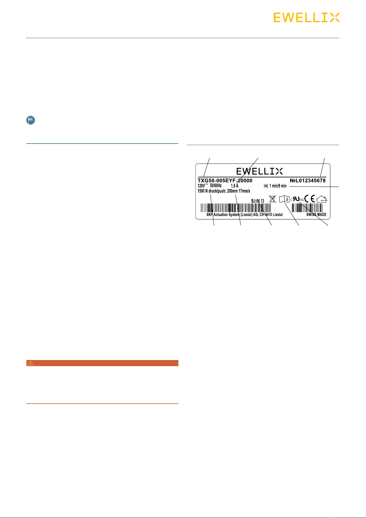
3.2 Product label...................................................................9
4.0 Structure and function...............................................10
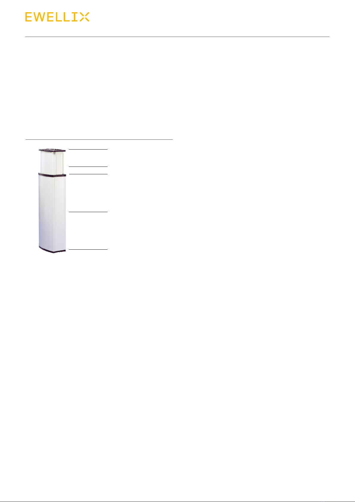
4.1 O ver view ........................................................................ 10
4.2 Functional description .................................................. 10
4.2.1 Requirements for third party control (Mandatory in
medical applications)........................................................ 11
4.3 Connections.................................................................. 11
4.4 Operating elements....................................................... 12
4.5 Options.......................................................................... 12
4.6 Accessories................................................................... 12
5.0 Transport, packaging and storage ...........................13
5.1 Safety information for the transport.............................. 13
5.2 Transport inspection..................................................... 13
5.3 Return to the manufacturer........................................... 13
5.4 Packaging...................................................................... 13
5.5 Storage.......................................................................... 14
6.0 Installation and rst operation ................................. 15
6.1 Installation location ....................................................... 15
6.2 Inspections prior to rst operation ............................... 15
6.3 Installation..................................................................... 16
6.4 Connect to the control unit ........................................... 17
6.5 Connection to operating element................................. 17
6.5.1 Connect TXG10 (stand alone) to operation element ..
17
6.5.2 Connect TXG (all types except TXG10) to operating
element ............................................................................. 17
6.6 Connect to power supply.............................................. 18
6.6.1 Connect TXG10 (stand alone) to power supply...... 18
6.6.2 Connect TXG (all types except TXG10) to power
supply ............................................................................... 18
6.7 Connect the second actuator “master/slave” (optional)19
6.8 Strain relief .................................................................... 19
7.0 Operation .....................................................................20
7.1 Safety .............................................................................20
7.2 Turn on........................................................................... 20
7.2.1 Turn TXG10 (stand alone) on ...................................20
7.2.2 Turn TXG (all types except TXG10) on ....................20
7.2.3 Turn o ....................................................................20
7.3 Action before use ..........................................................20
7.4 Actions during operation...............................................20
7. 4.1 S t a r t u p .....................................................................20
7.4.2 Instruction for use ................................................... 21
7.5 Disengagement in case of emergency .........................22
7.5.1 Shut down TXG10 (slave or standalone) .................22
7.5.2 Shut down TXG (all types except TXG10)...............22
8.0 Maintenance................................................................23
8.1 Maintenance plan .......................................................... 24
8.2 Maintenance work......................................................... 24
8.2.1 C lea ning .................................................................. 24
8.2.2 Inspections and readings.......................................25
8.2.3 Service log ..............................................................25
8.2.4 Check of visual condition .......................................25
8.3 Measures after completed maintenance......................25
9.0 Malfunctions................................................................26
9.1 Malfunction table........................................................... 27
9.1.1 Only actuators with main power connection (master /
stand-alone)......................................................................27
9.1.2 Only TXG10 (slave or stand alone) ..........................28
9.2 Start of operation after xing malfunction....................28
10.0 Dismantling................................................................29
10.1 Dismantling..................................................................29
10.2 Disposal.......................................................................29
11.0 Appendix ....................................................................30
WARNING
WARNING: read this manual before installing, operating or
maintaining this actuator. Failure to follow safety precautions and
instructions could cause actuator failure and result in seri ous
injury, death or property damage. Keep this manual nearby for
future reference.

4
Telesmart TXG
1.0 General information
1.1 Information in this
manual
This manual provides important information on how to work
with the actuator (also called device) safely and eciently.
The Manual is part of the device, must always be kept in the
device’s direct proximity and should be available for the per-
sonnel at any time. All personnel working with the device
must read and understand this Manual before starting any
work. Strict compliance with all specied safety notes and
instructions is a basic requirement for safety at work.
Moreover, the accident prevention guidelines and general
safety regulations applicable at the place of use of the de
vice must also be complied with.
For better representation of circumstances, the illustrations
used are not necessarily to scale and may vary from the ac-
tual design of the device.
All information and notes in this manual were compiled un-
der due consideration of valid standards and regulations,
the present status of technology and our years of knowledge
and experience.
1.2 Explanation of symbols
and signal words
Safety precautions
Warnings are identied by symbols and signal words. These
signal words indicate the severity of the hazard.
Adhere to these safety precautions and act cautiously in or-
der to avoid accidents, personal injuries and damage to
property.
DANGER
Indicates a dangerous situation, which
will lead to death or serious personal
injury, if the precautionary measures are
ignored.
WARNING
Indicates a dangerous situation, which
can lead to minor or moderate injury or
property damage, if the precautionary
measures are ignored.
CAUTION
Indicates a dangerous situation, which
can lead to minor or moderate injury
the precautionary measures are ignored.
NOTICE
Indicates information considered
important, but not hazard-related (e.g.
messages relating to property damage).
NOTE
Emphasizes useful hints and
recommendations as well as information
for ecient and trouble-free operation.

5
1.0 General information
1.3 Limitation of liability
The manufacturer will not be liable for damage resulting
from:
• disregarding this manual
• unintended use
• employment of untrained personnel
• unauthorized conversions
• technical modications
• manipulation or removal of the screws on the device
• use of unapproved spare parts
In case the actuator is customised, the actual product deliv-
ered may be dierent from what is described in the manual.
In this case, ask Ewellix for any additional instructions or
safety precautions relevant to these actuators.
We reserve the right to make technical modications to the
actuator to improve usability.
1.4 Copyright
This Manual is protected by copyright law and exclusively to
be used for internal purposes.
Passing this Manual on to third parties, duplication of any
kind – even in form of excerpts – as well as the use and/or
disclosure of the contents without the written consent of the
manufacturer is not permitted, except for internal purposes.
Violations oblige to compensation. The right for further
claims remains reserved.
1.5 Spare parts
The telescopic pillar TXG is not designed for repair work. All
warranty and service claims become void without notice if
any screws on the linear actuator have been manipulated.
WARNING
Safety hazard caused by wrong parts
Wrong or faulty spare parts can adversely aect safety and
cause damage, malfunctions or total failure.
Therefore:
• Use only genuine spare parts from the manufacturer
• Spare parts in/on the device may only be replaced by the manu-
facturer.
The device must be dismantled and sent to the
manufacturer.
1.6 Warranty terms
The applicable and eective warranty terms are those con-
tained in the manufacturer’s terms and conditions of sale.
1.7 Customer service
Ewellix Customer Service is always available to provide
technical information and answer questions.
Notes on the responsible contact partner are on call by
phone, fax, e-mail or via internet, see address of manufac-
turer on cover back.
In addition, our employees are always interested in acquiring
new information and experience gained from practical appli-
cation: such information and experience may help improve
our products.

6
Telesmart TXG
6
2.0 Safety
This paragraph provides an overview of all important safety
aspects for optimal protection of personnel as well as safe
and trouble-free operation.
Disregarding this Manual and safety regulations specied
therein may result in considerable danger and possible seri-
ous injury or death.
2.1 Use
2.1.1 Intended use
The telescopic pillar TXG have been designed and built ex-
clusively for the intended purposes as described below.
• These pillars are to be only used for a dynamic centric and
ocenter lift charged with pressure.
• These pillars have been especially designed for height ad-
justments of medical applications, computer work and as-
sembly tables Any other use of these pillars must be au-
thorized by the manufacturer.
• These pillars are only suitable for indoor applications and
may not be exposed to the outdoors, heavy UV radiation
or dusty, corrosive or explosive environments.
Any use that extends beyond the intended use or a use dif-
ferent than the one described above is deemed misuse.
WARNING
Risk from misuse
Any utilization of this device beyond its intended purpose may
lead to potentially hazardous situations..
Therefore:
• Strictly adhere to all safety precautions and instructions in this
operating manual.
• Do not make this device subject to weather conditions, strong UV
rays, corrosive or explosive air media as well as other aggressive
media.
• Do not modify, retool or change the structural design or individual
components of the actuator.
• Never use the device outside of the technical application and op-
erational limits.
Any injury, damage or loss caused by a failure to follow the
instructions in this manual will be the responsibility of the
purchaser.
2.1.1.1 Product life time
Telesmart telescopic pillar have been designed for a service
life of 10 000 double strokes at a stroke length of 300 mm
(this applies for a centric maximum load as per the data
label).
The Telesmart requires no maintenance during this period.
Internal tests must be performed if other requirements relat-
ing to service life are specied.
2.1.2 Unintended Use
Any use other than the intended use without the manufac-
tuer’s written agreement or operation beyond the technical
limits is considered unauthorized.
Specic excluded applications are:
• Flammable Anaesthetic Mixture with air
• Flammable Anaesthetic Mixture with Oxygen or nitrous ox-
ide increased radiation places exposed to water (wetrooms)
2.1.3 Essential performance
Holding or moving a load.
2.2 Responsibility of the
owner and processor
The device is designed both for personal use and for use in
in commercial applications by owner or processors.
The processor is the contracting partner of the reseller or
the manufacturer. The processor installs the device in a
complete system (application).
The owner or processor of the system is therefore subject to
the requirements of the Occupational Health and Safety Act.
In addition to the safety instructions in this Manual, the
owner or processor must do the following concerning these
safety and accident prevention guidelines and environmental
protection regulations, applicable to the site of the system’s
installation:
• Inform themselves of applicable industrial safety regula-
tions and determine additional hazards that arise due to
the specic working conditions prevailing at the site where
the device is installed using risk assessment. The risk

7
2.0 Safety
7
assessment must be implemented in the form of work in-
structions for device operation.
• Must conrm that the work instructions created for the
system in cluding the device satisfy current legal require-
ments and must alter the instructions if they don’t.
• Clearly regulate and specify the responsibilities for installa-
tion, operation, maintenance, and cleaning.
• Ensure that all employees who deal with the device have
read and understood this Manual.
• Provide personnel with the required protective equipment.
• In addition, owner must train personnel at regular intervals
and inform personnel of the hazards.
In addition, owner or processors must ensure that the device
is in adequate working condition. They must do the
following:
• Ensure that the maintenance intervals described in these
instructions are complied with.
• Have all safety devices inspected regularly for to ensure
proper functionality.
2.3 Personnel
requirements
WARNING
Improper installation, operation and maintenance can result in
serious injury, death or property damage.
Use only qualified, instructed, or trained personnel (as described
below) who have read, understand and follow these instructions.
2.3.1 Qualications
The following qualications are specied for dierent areas
of activity listed in the manual.
• An instructed person (Operator)
has been instructed by the customer in an orientation ses-
sion on the assigned tasks and possible dangers in case of
improper behaviour.
• Qualied personnel
based on their professional training, know-how and experi-
ence as well as knowledge of the applicable standards and
regulations is able to perform assigned work activities and
to detect and avoid possible dangers on their own.
• A professional electrician
based on his/her professional training, know-how and ex-
perience as well as knowledge of the applicable standards
and regulations is able to perform work on electrical sys-
tems and to detect and avoid possible dangers on his/her
own.
The professional electrician has been trained for the spe-
cial location where he/she works and knows the relevant
standards and regulations.
Only persons who are expected to perform their tasks relia-
bly are permitted as personnel. Persons whose reaction ca-
pability is impaired, e.g. through drugs, alcohol or medica-
tion, are not permitted.
2.4 Specic dangers
The following section lists the residual risks that have been
determined by the risk assessment.
• Heed the safety instructions listed here, and the warnings
in subsequent chapters of this Manual, to reduce health
hazards and to avoid dangerous situations.
DANGER
Danger to life caused by electric current!
Touching conductive parts causes a direct danger to life. Damage
to insulation or individual components can cause danger to life.
Therefore:
• In the event of damage to insulation, switch o the power supply
immediately and have the parts repaired.
• Work on the electrical system must be carried out only by profes-
sional electricians.
• De-energize the system for all work on the electrical system.
• Before maintenance, cleaning or repair work, switch o the power
supply and perform lockout procedures so it cannot be turned on
again.
• Do not bridge fuses or make them ineective. When changing
fuses, make sure you use the correct amperage.
• Keep moisture away from conductive parts. If you do not, this can
cause short circuit.
WARNING
Danger of injury caused by moving components!
Rotating and/or linearly moving components can cause severe
injury.
Therefore:
Do not work on or place any of your body, hands, or arms near
moving components.
2.5 Safety equipment
Integration of an emergency-stop system (for
certain applications)
The device is only intended for installation into an an appli-
cation system It does not have its own operating control ele-
ments and does not have an independent emergency-stop-
function.
Install the device so that it is part of an emergency shut-o
system and can be stopped if necessary.

8
Telesmart TXG
8
The emergency shut-o system has to be connected in such
a way that a disruption of the power supply or the reactiva-
tion of the power supply after a power disruption cannot
cause a hazardous situation for persons and objects.
The emergency shut-o systems must always be freely
accessible.
Integration of an emergency-stop system (for
certain applications)
The device is only intended for installation into an applica-
tion or system It does not have its own operating control ele-
ments and does not have an independent patient release
mechanism.
If required by the application, a seperate provision for pa-
tient release has to be installed to allow safe release of a pa-
tient in case of emergency or equipment failure.
To increase more safety, anti-pinching
protection can also be connected (optional).
NOTE
The processor decides which application require the installation of
the following safety systems:
• Emergency shut-o system
• Patient release system
• Anti-pinching protection
NOTE
The TXG telescopic pillar does not contain displaying operational
conditions. For end applications in medical field it is mandatory to
ensure displaying operational conditions.
The following safety features may have been
installed:
• The TXG telescopic pillar is tted with a thermoswitch. The
thermoswitch integrated into the transformer switches the
actuator o if the temperature becomes excessive. For
TXG10 a thermal protection must be provided by the used
control unit.
• End limit switches are installed to provide a safe current
cut o when the end position of the device is reached. In
case of failure of the end limit switches, an additional limit
switch prevents the device from exceeding its intended
stroke.
2.6 Safeguard against
restart
DANGER
Life-threatening situation through unauthorized restart!
For work in hazard zones, there is a risk that the power supply is
turned on without prior authorization. This presents a lifethreatening
situation for people in the hazard zone.
Therefore:
• Follow the information concerning the safeguarding against
re-starting of the power supply in the chapters of this operating
manual.
• Always follow the process to safeguard against a restart as de-
scribed below.
Protect TXG (AC version) against a restart.
Pull the power line plug out of the power outlet.
Protect TXG1 (DC version) against a restart.
Pull the power line plug of the Ewellix control unit or a mas-
ter actuator out of the power outlet.
WARNING
To avoid hazardous situations and to ensure optimal performance,
do not make any changes or modifications to the device unless they
have been specifically authorized by Ewellix.
2.7 Modications of
device
2.7.1 Warning labels
The following symbols and information decals can be found
in the danger zone. They refer to the immediate vicinity
around their location.
WARNING
Danger of injury because of illegible symbols
Over the course of time stickers and decals may become dirty or
illegible for some other reason.
Therefore:
• Keep any safety, warning and operation related decals in legible
condition at all time.
• Replace damaged decals or stickers immediately.

9
3.0 Technical data
9
3.0 Technical data
NOTE
The technical data (dimensions, weight, output, connection values
etc.) can be found in the enclosed drawings and data sheets.
3.1 Ambient conditions
Operation
Indoor use only at:
• Ambient temperature +10 to +40 °C
• Relative humidity max. 85%
• Air pressure from 700 to 1 060 hPa
• Maximum altitude 3 000 m (MOPP)
• Supply mains with overvoltage category I
• Pollution degree 2
Storage/Transport
• Temperature –20 to +40 °C
• Humidity max. 95%
Operating mode
• Intermittent 10%; 1 min ON / 9 min OFF
The actuator has been designed for intermittent operation.
If a higher duty cycle is used, contact Ewellix.
The TXG is thermaly protected. The thermoswitch itegrated
into the transformer winding switches the actuator o if the
temperature becomes excessive.
WARNING
If the duty cycle is excessively long, the TXG may be
temporarily unserviceable!
When the actuator has cooled down, the mains connector must
be disconnected from the mains power supply for approximately 1
minute to reset the thermoswitch.
CPMA1-12400AA0-000 №L05703726
100–240 V~
max. 1 000 Npush
Auxiliary power max. 8 A
SWISS MADE
BJ:10.13
400 mm
C
IP20
50/60 Hz max. 1,5 A Int. 1 min/9 min
Ewellix (Liestal) AG, CH-4410 Liestal
Fig. 1
3.2 Product label
The product label provides the following information:
1. Identication of type
2. power consumption
3. Serial number
4. Power-on time
5. Inspection mark
6. Consult accompanying documents
7. Manufacturing date (month/year)
8. Stroke lenght and pillar speed
9. Compressive force
1 2 3
4
5
6789

10
Telesmart TXG
4.0 Structure and function
4.1 Overview
4.2 Functional description
Explanation of terms
Stand-alone Actuator with integrated control unit
and power supply which is used as an
individual lifting column.
Master Actuator with integrated control unit
and power supply and possible
connection for a further actuator.
Slave Actuator without integrated control unit
and power supply. Can be used in
combination with a master actuator or a
separate control unit.
Master-slave Two actuators, the master performing
the control function and handling the
power supply for the slave. (No parallel
operation)
The TXG is an electrical linear actuator which uses virtually
play-free guide tubes. It has been designed for holding and
moving centric and eccentric loads. acc. data sheet.
Fig. 2
1
2
3
4
5
1. Base plate top
2. Inner tube
3. Rim cover
4. Outer tube
5. Base plate bottom

11
4.0 Structure and function
A DC motor controls a threaded spindle via a bevel gear.
A threaded nut moves up and down on the spindle. This nut
is secured to the push tube and thereby generates a forward
motion. The telescopic tubes are inserted and retracted de-
pending on the direction of the motor.
Where the TXG is equipped with a mains connection (stand-
alone and master), the mains voltage is transformed to 24 V
and rectied. The slave actuator is a 24 V DC unit.
Control unit (stand-alone and master)
The DC motor is fed via an integrated control unit.
• The simple control PCB contains a relay circuit which con-
trols the running direction of the actuators.
• Where actuators are equipped with the “Parallel running”
and/or “Memory” option, a microprocessor takes charge
of control and regulation operations. These actuators are
equipped in the factory with an encoder for position detec-
tion. If a slave actuator is to be connected, it must also be
equipped with an encoder. These actuators are also
equipped with a “soft start” function, i.e. the actuators
start up smoothly, without any jerks. The “Memory” option
decelerates the actuators using a “soft stop” before they
reach the saved position.
The TXG is to a great extend protected against failures.
However a rst failure safety can’t be guaranteed because of
unvorseeable defects, for example a control Element, which
can lead to slow uncontroled movements.
WARNING
First failure safety of the assembled equipment has to be verified in
the particular application to prevent danger for life and limb.
Terminal-position shutdown
The stroke is limited by the integrated limit switches. If the
actuator moves beyond one of these switches (in the case of
a malfunction), an additional limit switch comes into play.
The actuator power circuit is interrupted and the actuator
can then no longer be moved (⮑8 Maintenance, page 23).
NOTE
Additional differences between the TXG pillars can be found in the
appendix (⮑ 11 Appendix, page 30).
4.2.1 Requirements for third party
control (Mandatory in medical
applications)
These requirements are applicable for TXG10 types (stand
alone). Control units which are not approved for TXG by
Ewellix are treated as third party controls.
• Separated from supply mains by 2 MOPP
• Over current cut o
• “Puch-to-run” operation (recommended): The actuator op-
erates as long as the switch is pressed
• Displaying operational conditions
4.3 Connections
Fig. 3
123 4
Connections for the following are marked on the TXG:
1. Mains cable (N,L,PE)
2. Electrical anti-pinching protection (optional)
3. Operating element (10 pole RJ45)
4. Second actuator for master/slave operation (optional,
DIN-8 plug)

12
Telesmart TXG
4.4 Operating elements
TXG10 (stand alone)
NOTE
The device does not feature its own operating elements The
operation takes place via a Ewellix operating element at an external
Ewellix control (⮑ Separate operating manual).
TXG (all types except TXG10)
NOTE
The device does not feature its own operating elements The
operation takes place via a Ewellix operating element which is
connected directly to the device. (⮑ Separate operating manual).
Requirements for operating elements
(mandatory in medical applications)
General safety requirements according IEC 60601-1:2005.
Suitable Ewellix operating elements are given in section
Accessories.
4.5 Options
• Mains cable feedthrough (max. 250 V AC, 50/60 Hz; load 6 A).
The TXG is isolated. The protective conductor is only fed
through and is not connected to the metal elements of the
telescopic column.
• Connection for controls, feedthrough
• Connection for second actuator (master/slave operation)
• Guide tube, powder-coated
• Connection for electrical anti-pinching protection
NOTE
Protection class II applies for TXG as standard.
Protection class I with feedthrough protective conductor applies
for the TXG with mains cable feedthrough. The mains cable
feedthrough is fused with 6,3 A on both sides.
The aluminium tubes have no earth wire connection.).
4.6 Accessories
Accesories Comments
Cable for electrical
anti-prinching protection
To increase safety, anti-pinching
protection can be connected
(optional)
Ewellix operating element Handswitch (EHE), deskswitch,
footswitch (Comfodesk)
Mains cable 2-core or 3-core, country
specic
Mounting plates Colourless anodised nish
Accesories listed above are not included and must be ordered
separately.

13
5.0 Transport, packaging and storage
5.0 Transport, packaging and
storage
5.1 Safety information for
the transport
CAUTION
Damage due to improper transport
Significant material damage can occur in conjunction with improper
transport.
Therefore:
• Proceed carefully during the unloading of the packaged items,
during the delivery as well as during the transport to its nal desti-
nation and comply with the symbols and information shown on
the packaging
• Only remove the actuator from its packaging right before installa-
tion
• Note storage requirements for return transport to the manufac-
turer (⮑ 5.5 Storage, page 14).
5.2 Transport inspection
The TXG telescopic pillar is delivered as one packaged unit
in a box or on pallets.
Check the delivery for completeness and damage due to
transport immediately upon receipt.
Check completeness of delivery
The TXG consist of:
• the complete lifting column (guide tube, colourless ano-
dised nish)
• 8 x fastening screws M6x40 DIN 7500
• assembly instructions
• connecting cable (“slave” only)
Mains cable for specic countries can be ordered
separately.
Proceed as follows in conjunction with visible exterior trans-
port damage:
• Do not accept delivery or do so only with reservations.
• Record scope of damage on the transport documents or
on the bill of delivery of the shipping company.
• Initiate complaint.
NOTE
Report any damage as soon as it has been recognized.
Damage claims can only be asserted within the transporter’s
applicable complaint period.
5.3 Return to the
manufacturer
Proceed as follows for the return transport:
1. Dismantle the device if necessary (⮑ 10 Dismantling,
page 28).
2. Pack device in its original packaging Follow storage con-
ditions (⮑5.5 Storage, page 14).
3. Send to manufacturer. The address is listed on the cover
back.
5.4 Packaging
For packaging
The individual packaged pieces have been packaged appro-
priately according to the expected transport conditions Only
environmentally friendly materials were used for the
packaging
The packaging is supposed to protect the individual compo-
nents from damage caused by the transport, corrosion and
other damage until they are ready for installation Therefore,
do not destroy the packaging and only remove it shortly prior
to the installation Keep packaging for possible return ship-
ment to the manufacturer (⮑5.3 Return to the manufac-
turer, page 13).
If the packaging is to be disposed o, please note and ad-
here to the following:
CAUTION
Environmental damage due to incorrect disposal
Packaging material consists of valuable raw materials and in
many cases they can be sensibly recycled and reused
Therefore:
• Dispose of packaging material in an environmentally correct way
• Comply with locally applicable disposal regulations

14
Telesmart TXG
5.5 Storage
Pack the actuator in its original packaging for storage.
• Do not store outside.
• Dry and dust-free storage.
• Keep away from any aggressive media.
• Protect from UV radiation.
• Avoid mechanical vibrations.
• Storage temperature: –20 to 40 °C.
• Relative atmospheric humidity: max. 95% (no build up of
condensation).
• For storage for longer than three months, check the gen-
eral condition of all parts of the packaging on a regular ba-
sis. If necessary, refresh or renew the conservation.
NOTE
It is possible that there are notices on the packaging concerning
the storage, which go beyond the requirements listed here. Follow
those accordingly.

15
6.0 Installation and first operation
6.0 Installation and rst operation
Authorized personnel
• The installation and rst start of operation may only be
conducted by qualied personnel.
• Work on the electric system may only be performed by
trained electricians.
WARNING
Electric shock and moving parts hazards
Serious injury or death can be caused by touching live electrical
components and by unexpected movement of the actuator.
Be sure the system’s power supply is off and actuator is locked
out before installing.
WARNING
Danger if restarted without authorization!
When correcting faults, there is danger of the energy supply being
switched on without authorization. This poses a lifethreatening
hazard for persons in the danger zone.
Therefore:
• Prior to starting work switch o the system and safeguard it from
being lockout.
WARNING
Risk of injury and material damage due to incorrect installation
of the optional devices!
Therefore:
• Optional devices, in particular components that are part of
a retrotting, may only be installed in accordance with the respec-
tive instructions (circuit diagram).
• The electromagnetic compatibility must be tested for the routing
and appropriate measures must be carried out if necessary.
6.1 Installation location
• Adhere to the technical data in accordance with operating
conditions.
• Install in a location where the actuator is not exposed to
strong UV radiation or corrosive or explosive air media.
6.2 Inspections prior to
rst operation
• Execution by professional electrician
Prior to the rst operation, a professional electrician must
perform and document the following tests and readings:
• Check visual condition
• Function check of operating features and safety features
• Reading of leakage currents
• Reading of insulation resistance
NOTE
Additional information concerning inspections and
readings (⮑ 8 Maintenance, page 23).

16
Telesmart TXG
6.3 Installation
• Execution by qualied personnel
WARNING
Risk of injury and material damage due to manipulation of the
screws on the device
Manipulation or loosening of the screws on the device or on the
options may lead to injuries and material damage during the
operation.
Therefore:
• Never loosen screws on the device or the options.
Please pay attention to the installation instructions which are
delievered with the device.
The TXG can be secured to either Ewellix mounting plates
(⮑ 4.6 Accessories, page 12) or the customer’s own
plates. Plastic base plates are tted to the end faces of the
outer and inner tubes. The mounting plates are secured to
the aluminium tubes by means of four bores in each of the
base plates. When the screws are screwed in, a thread is
formed in the prepressed holes in the aluminium tube. The
outer tube is screw-connected using the outer bores (⮑ g. 4),
while the inner tube is screw-connected by means of the in-
ner bores (⮑ g. 5).
Fig. 4
4 x M6x40 DIN7500
(9-11 Nm)
4 x M6x40 DIN7500
(9-11 Nm)
Fig. 5
4 x M6x40 DIN7500
(9-11 Nm)
4 x M6x40 DIN7500
(9-11 Nm)
Any subsequent fastening bores in the aluminium tubes may
only be made by Ewellix. The sides of the inner tubes must
not be scratched, otherwise the tube guide will be damaged.
This can result in malfunctions.
CAUTION
Only use the screws supplied (M6 x 40 DIN 7500).
Ensure that the screws are inserted to a minimum depth of
25 mm and that the torque is 9 to 11 Nm.
CAUTION
Do not form a thread into the bores with a thread tap.
The actuator may be damaged.
CAUTION
When using your own mounting plates, ensure that the base
plates are supported over their full area.
The base plates may be damged.
WARNING
Risk of injury and material damage!
Pay particular attention to avoid anything may be squeezed
between the base plates of the inner and the outer tube.
WARNING
Risk of injury and material damage!
Ensure that metal mounting plates are not grounded using the TXG.
They must be grounded or insulated by the customer if required.
In case of using additional equipment which has not protection
class II, the mounting plate must be connected to the earth wire.

17
6.0 Installation and first operation
6.4 Connect to the
control unit
NOTE
This section is applicable for slave types of TXG (TXG10) without
integrated control unit and power supply which can be used with a
separate external control unit.
All control units which are not approved for the TXG devices
by Ewellix are treated as third party controls.
CAUTION
Material damage due to third-party control unit
The use of a third-party control unit may lead to material damage.
In conjunction with the use of a thir d-party control unit, the
manufac-turer does not assume any liability for damage that may
be caused.
Therefore:
• It is recommended to use the Ewellix control unit from the manu-
facturer.
• When using the third-party control unit, the requirements stipu-
lated for the third-party control unit must be adhered to (⮑ 4.2.1
Requirements for third party control unit, page 11).
NOTE
A low-voltage plug connects the device to an external control unit.
Adhere to the instructions of the operating manual of the Ewellix
Control unit during the connection process.
The low-voltage plug has been tted with a DIN-8 plug.
Connec the external control unit o the eight-pin socket
marked “Slave” (⮑ g. 3 on page 11) using the connection
cable.
Ensure that the plug is correctly seated. The nose of the
plug must face upwards (⮑ g. 6).
Fig. 6
NOTE
Please adhere also to the instructions of the control unit
regarding connection.
6.5 Connection to
operating element
WARNING
Risk of injury and material damage due to third party
operating element
The use of a third party operating element may lead to significant
injuries or material damage.
In conjunction with the use of a third-party operating element, the
manufacturer does not assume any liability for damage that may be
caused.
Therefore:
• Only use the manufacturer’s Ewellix operating element. In case of
using additional equipment which has not protection class II, the
mounting plate must be connected to the earth wire
6.5.1 Connect TXG10 (stand alone) to
operation element
NOTE
The device is connected to the operating element via an external
control (⮑ Separate operating manual of the control and the
operating element).
6.5.2 Connect TXG (all types except
TXG10) to operating element
NOTE
The device is connected directly to an operating element.
Adhere to the operating instructions for the operating elements in
regard to the connection (⮑ Separate oprating manual).
The operating element is tted into the socket 3 (⮑ g. 3
on page 11).
Fig. 7
Ensure that the nose of the plug engages correctly ("click").

18
Telesmart TXG
Then t a cable tie 3in order to secure the wires. The cable
tie should be secured as close to the clamp as possible.
Each wire (L and N on the electric circuits), is protected by a
fuse. If one or both of these fuses are tripped out, replace-
ment of the actuator will be necessary.
It is possible to order the actuator without internal fuse. In
this case, the customer is responsible for adding the correct
electrical protection (two fuses, max. 6,3 AT).
NOTE
When using your own mains cables, comply with the following
specification:
H0W-FVDE 0,75 mm2, wires 5-6 mm stripped.
NOTE
L = phase conductor
N = neutral conductor = earth wire (option mains cable feedthrough
DANGER
It is important to secure the cable tie. Otherwise in case of
loosing a braid from the clamp, an electrical shock hazard could
result because of high leakage current.
Mains cable feedthrough (optional)
The earth wire must be at least 20 mm longer than the re-
maining wires in order to provide full protection.
DANGER
Electrical shock hazard!
Ensure that only one mains cable is connected (either top or
bottom) at any one time. Otherwise the actuator may be damaged.
6.6 Connect to power
supply
6.6.1 Connect TXG10 (stand alone) to
power supply
NOTE
The device is connected to the operating element via an external
control (⮑ Separate operating manual of the control and the
operating element).
1. Connect linear actuator to control unit (⮑ g. 3 on page
11).
2. Connect control to electric grid (⮑ Separate operating
manual for control).
3. Ensure that the plug of the power line is accessible at all
times.
6.6.2 Connect TXG (all types except
TXG10) to power supply
DANGER
Electrical shock hazard!
Incorrect installation can result in serious injuries, death or damage.
Only professional electricians should work on electrical systems
Connecting the mains cable
Connect the mains cable to the connection as shown
in gure 8.
Fig. 8
1
2
NL
3
Pay particular attention to how the wires are assigned. The
clamp for the earth wire is only provided in the case of the
optional mains cable feedthrough.
Proceed as follows to introduce the individual wires (⮑ g.8 ):
1. Press the lever 1of the clamp downwards using a size 1
screwdriver
2. Insert the stripped wire into the opening 2
3. Release the lever again.

19
5.0 Transport, packaging and storage
6.8 Strain relief
Run all the cables through the ducts in the base plate to the
outside. (⮑ g. 10). This provides the necessary strain re-
lief. Depending on the particular application, you can run the
cables to the rear (A1) or to the side (B). If you run the cables
to the front (A2), you have to ensure strain relief separatly.
The narrow ducts are suitable for cable diameters of 4,5 to
5,5 mm and the wider ducts for cable diameters of 5,5 to 7,5 mm.
Fig. 10
A1
B
A2
For strain relief requirements according IEC 60601-1:2005
following applies:
1. Cord with 2 braids (2 x 0,75 mm2 ) →the narrow duct of
B suitable
2. Cord with 3 braids (3 x AWG) →all ducts of A1 and B
suitable
CAUTION
Electric cables should not be exposed to pinching, bending or
tensile loads.
NOTE
If you do not run the cables through the ducts or you run the cables
as shown in fig. 10, A2, you must provide design measures to be
ensure adequate strain relief.
6.7 Connect the second
actuator “master/slave”
(optional)
Connect the second actuator to the eight-pin socket marked
“Slave” (⮑ g. 9) using the connection cable.
Fig. 9
Ensure that the plug is correctly seated. The nose of the plug
must face upwards.
CAUTION
For use with a master with “parallel running” and/or “memory”,
the slave has to be equipped with an encoder. The master may be
damaged.
Otherwise a slave with encoder should not be connected to a
master without “parallel running” and/or “memory”. The slave be
damaged.

20
Telesmart TXG
7.1 Safety
DANGER
Risk of crashing!
While moving onto solid objects, the force of the device may
cause injuries.
Therefore:
• Ensure that there are no persons in the stroke area of the
device while in operation.
• Take note of maximum permissible operating data for the
device (⮑ 11 Appendix, page 30).
• Never tamper with the elements that are connected to the device
while the device is in operation.
CAUTION
Material damage due to static and dynamic overload of the
device
Static and dynamic overload can lead to damage and failure of the
device.
Therefore:
• Adhere to maximum permissible operating data for the device
(⮑ 11 Appendix, page 30).
• Never exceed nominal load.
• Never tamper with the elements that are connected to the device
while the device is in operation.
CAUTION
The device may be damaged if liquids penetrate the actuator during
extension and retraction. Keep liquids away.
7.2 Turn on
7.2.1 Turn TXG10 (stand alone) on
NOTE
The device does not feature its own operating control unit. The
operation takes place via a separate control unit (⮑ Separate
operating manual).
7.2.2 Turn TXG (all types except TXG10) on
NOTE
After the Connection to power supply and to operating element has
been done (⮑ 6 Installation and first operation, page 15) the
actuator is ready to operate.
7.2.3 Turn o
NOTE
The device does not feature its own operating elements. The
operation takes place via a separate operating element
(⮑ Separate operating manual).
7.3 Action before use
CAUTION
Ensure that there are no persons or objects in the stroke
area of the device.
7.4 Actions during
operation
7.4.1 Startup
The lifting column – without any additional functions – is
ready for operation once the correct electrical and mechani-
cal connections have been made.
Before the TXG can be used in parallel operation or with the
memory function, an initialisation run must rst be
performed.
Initialisation run for parallel operation
Run the actuators using directional buttons and on the
control device in counter- load direction a single time as far
as the terminal position (= reference point). Hold the button
depressed until all actuators have reached the terminal posi-
tion and have come to a stop .
Initialisation run for memory function
Run each actuator individually using directional buttons
and on the control device in counter-load direction a
single time as far as the terminal position (=reference point).
Hold the button depressed until the actuator has reached
the terminal position and has come to a stop.
NOTE
If no initialisation run is performed in parallel mode, the control unit
assumes synchronised actuators are being used and travels with a
stagger.
7.0 Operation
This manual suits for next models
5
Table of contents
Popular Outdoor Light manuals by other brands

BEGA
BEGA 84 128 Installation and technical information

ARC Lighting
ARC Lighting Tiny Monster Concept Series quick start guide

Trio
Trio BALOUBET 4282102 Series quick start guide

Lumena
Lumena Charleston Brick Light instructions

Maretti
Maretti WOLTERINCK COSTA I WALL quick start guide

OBI
OBI Lioni 800361 Original operating instructions

Winsome house
Winsome house WH096 instruction manual

MaxLite
MaxLite ML1E 2DAR Series operating instructions

WE-EF
WE-EF ZTY630 LED Installation and maintenance instructions

Acuity Brands Lighting
Acuity Brands Lighting Holophane High Mast System 2 Operation & maintenance manual

HOMCOM
HOMCOM B31-439V90 quick start guide

Gewa
Gewa PL-39 instruction manual