manuals.online logo
Brands
  1. Home
  2. •
  3. Brands
  4. •
  5. BEGA
  6. •
  7. Outdoor Light
  8. •
  9. BEGA 84 992 User manual

BEGA 84 992 User manual

BEGA Gantenbrink-Leuchten KG · Postfach 31 60 · 58689 Menden · info@bega.com · www.bega.com 1/4
10.20 · Technische Änderungen vorbehalten · Technical amendments reserved · Modications techniques réservées
IP 65
!
Lichtbauelement
Light building element
Prolé lumineux
84 992
r
50001000
600
500
1600
Ø 170
Ø 76
150
300x 85
Gebrauchsanweisung Instructions for use Fiche d’utilisation
Anwendung
Lichtbauelement mit rotationssymmetrischer
Lichtstärkeverteilung für die Beleuchtung und
die Gestaltung von Plätzen, Zufahrten und
Eingangsbereichen.
Lichtbauelemente sind Leuchten, die
Außenräume gliedern und strukturieren können.
Sie haben eine orientierende, leitende und
begrenzende Funktion.
Application
Light building element with rotationally
symmetrical light distribution for lighting and
designing squares, access roads and entrance
areas.
Light building elements are luminaires which
can devide and structure areas in exterior
application. They have a orientating, directing
and demarcating function.
Utilisation
Prolé lumineux à répartition lumineuse
à rotation symétrique, pour l’éclairage et
l’aménagement de places, de voies d'accès
et d'entrées. Les prolés lumineux sont des
luminaires permettant de dénir et de structurer
les espaces extérieurs.
Ils ont une fonction d'orientation, de balisage et
de délimitation.
Leuchtmittel
Modul-Anschlussleistung 62,4W
Leuchten-Anschlussleistung 69W
Bemessungstemperatur ta=25 °C
Umgebungstemperatur ta max = 50 °C
84 992 K4
Modul-Bezeichnung 12x LED-0701/840
Farbtemperatur 4000K
Farbwiedergabeindex CRI > 80
Modul-Lichtstrom 12420lm
Leuchten-Lichtstrom 10457lm
Leuchten-Lichtausbeute 151,6 lm / W
84 992 K3
Modul-Bezeichnung 12x LED-0701/830
Farbtemperatur 3000K
Farbwiedergabeindex CRI > 80
Modul-Lichtstrom 12060lm
Leuchten-Lichtstrom 10154lm
Leuchten-Lichtausbeute 147,2 lm / W
Lamp
Module connected wattage 62.4W
Luminaire connected wattage 69W
Rated temperature ta=25 °C
Ambient temperature ta max = 50 °C
84 992 K4
Module designation 12x LED-0701/840
Colour temperature 4000K
Colour rendering index CRI > 80
Module luminous ux 12420lm
Luminaire luminous ux 10457lm
Luminaire luminous efciency 151,6 lm / W
84 992 K3
Module designation 12x LED-0701/830
Colour temperature 3000K
Colour rendering index CRI > 80
Module luminous ux 12060lm
Luminaire luminous ux 10154lm
Luminaire luminous efciency 147,2 lm / W
Lampe
Puissance raccordée du module 62,4W
Puissance raccordée du luminaire 69W
Température de référence ta=25 °C
Température d’ambiance ta max = 50 °C
84 992 K4
Marquage des modules 12x LED-0701/840
Température de couleur 4000K
Indice de rendu des couleurs CRI > 80
Flux lumineux du module 12420lm
Flux lumineux du luminaire 10457lm
Rendement lum. d’un luminaire 151,6 lm / W
84 992 K3
Marquage des modules 12x LED-0701/830
Température de couleur 3000K
Indice de rendu des couleurs CRI > 80
Flux lumineux du module 12060lm
Flux lumineux du luminaire 10154lm
Rendement lum. d’un luminaire 147,2 lm / W
BEGA Gantenbrink-Leuchten KG · Postfach 31 60 · 58689 Menden · info@bega.com · www.bega.com
2/4
Sicherheit
Für die Installation und für den Betrieb
dieser Leuchte sind die nationalen
Sicherheitsvorschriften zu beachten.
Die Montage und Inbetriebnahme darf nur
durch eine Elektrofachkraft erfolgen.
Der Hersteller übernimmt keine Haftung für
Schäden, die durch unsachgemäßen Einsatz
oder Montage entstehen.
Werden nachträglich Änderungen an der
Leuchte vorgenommen, so gilt derjenige als
Hersteller, der diese Änderungen vornimmt.
Safety indices
The installation and operation of this luminaire
are subject to national safety regulations.
Installation and commissioning may only be
carried out by a qualied electrician.
The manufacturer is then discharged from
liability when damage is caused by improper
use or installation.
If any luminaire is subsequently modied, the
persons responsible for the modication shall
be considered as manufacturer.
Sécurité
Pour l’installation et l’utilisation de ce luminaire,
respecter les normes de sécurité nationales.
L’installation et la mise en service ne doivent
être effectuées que par un électricien agréé.
Le fabricant décline toute responsabilité
résultant d’une mise en œuvre ou d’une
installation inappropriée du produit.
Toutes les modications apportées au luminaire
se feront sous la responsabilité exclusive de
celui qui les effectuera.
Überspannungsschutz
Die in der Leuchte verbauten elektronischen
Komponenten sind nach DINEN61547 gegen
Überspannung geschützt.
Um einen zusätzlichen Schutz z.B. vor
Transienten etc. zu erreichen, empfehlen wir
separate Überspannungsschutzkomponenten.
Sie nden diese auf unserer Website unter
www.bega.com.
Overvoltage protection
The electronic components installed in the
luminaire are protected against overvoltage in
accordance with DINEN61547.
To achieve an additional protection against
e.g. transients, etc. we recommend separate
overvoltage protection components.
You can nd them on our website at
www.bega.com.
Protection contre les surtensions
Les composants électroniques installés dans
le luminaire sont protégés contre la surtension
conformément à la norme DINEN61547.
Pour obtenir une protection supplémentaire
contre la surtension, les tensions transitoires
etc., nous proposons des composants de
protection séparés. Vous les trouverez sur notre
site web www.bega.com.
Produktbeschreibung
Leuchte besteht aus Aluminiumguss,
Aluminium und Edelstahl
Beschichtungstechnologie BEGA Unidure
®
Kunststoffzylinder weiß
Mast aus Aluminium
2 gegenüberliegende Kabeleinführungen
150 ×50 mm
Anschraubbare Grundplatte ca. 250 ×250 mm
Erdstücklänge 1000 mm
Mit eingesetzter Tür aus Aluminium
Vierkant-Türverschluss (SW 8 mm)
Anschlusskasten 71 084
zur Durchverdrahtung – für 2 Kabel bis 7 ×6@
Klemmenbelegung L1· L2 · L3 · N · PE
2 Anschlussklemmen zum Anschluss
von DALI Steuerleitungen
Sicherungsklemme mit Feinsicherung
6,3 A träge ø 5 ×20 mm
BEGA Ultimate Driver
®
LED-Netzteil
220-240V x 0/50-60Hz
DC 176-264V
DALI steuerbar
Zwischen Netz- und Steuerleitungen ist eine
Basisisolierung vorhanden
BEGA Thermal Control
®
Temporäre thermische Regulierung der
Leuchtenleistung zum Schutz temperatur-
empndlicher Bauteile, ohne die Leuchte
abzuschalten
Schutzklasse I
Schutzart IP 65
Staubdicht und Schutz gegen Strahlwasser
Schlagfestigkeit IK08
Schutz gegen mechanische
Schläge < 5 Joule
r– Sicherheitszeichen
c – Konformitätszeichen
Windangriffsäche:0,87m²
Gewicht: 43,0 kg
Product description
Luminaire made of cast aluminium,
aluminium and stainless steel
BEGA Unidure
® coating technology
Synthetic cylinder, white
Pole made of aluminium
2 opposing cable entry points 150 ×50 mm
Screw-on ground plate approx. 250 ×250 mm
Length of anchorage section 1000 mm
With inserted door made of aluminium
Square door latch (wrench size 8 mm)
Connection box 71 084
for through-wiring – for 2 cables up to 7×6@
Terminal connection L1· L2 · L3 · N · PE
2 connecting terminals for connecting DALI
control cables
Fuse terminal with micro fuse
6,3 A slow ø 5 ×20 mm
BEGA Ultimate Driver
®
LED power supply unit
220-240V x 0/50-60Hz
DC 176-264V
DALI controllable
A basic isolation exists between power cable
and control line
BEGA Thermal Control
®
Temporary thermal regulation to protect
temperature-sensitive components without
switching off the luminaire
Safety class I
Protection class IP 65
Dust-tight and protection against water jets
Impact strength IK08
Protection against mechanical
impacts < 5 joule
r– Safety mark
c – Conformity mark
Wind catching area:0.87m²
Weight: 43.0 kg
Description du produit
Luminaire fabriqué en fonderie d’aluminium,
aluminium et acier inoxydable
Technologie de revêtement BEGA Unidure
®
Cylindre synthétique blanc
Mât en aluminium
2entrées de câble opposées 150 × 50mm
Plaque de stabilisation à visser 250 × 250mm
Pièce à enterrer 1000 mm
Avec porte fabriquée en aluminium
Fermeture à vis à quatre pans (taille de
clé8mm)
Boîte de connexion 71 084 pour branchement
en dérivation pour 2 câbles max. 7 ×6@
Disposition de bornes L1· L2 · L3 · N · PE
2 bornes pour le raccordement du câbles de
commande DALI
Porte fusible avec fusible à l n
6,3 A lent ø 5 ×20 mm
BEGA Ultimate Driver
®
Bloc d’alimentation LED
220-240V x 0/50-60Hz
DC 176-264V
Pilotage DALI
Une isolation d’origine existe entre le réseau et
les câbles de commande
BEGA Thermal Control
®
Régulation thermique temporaire de la
puissance des luminaires pour protéger les
composants sensibles à la température, sans
pour autant éteindre les luminaires
Classe de protection I
Degré de protection IP 65
Etanche à la poussière et protégé contre les
jets d’eau
Résistance aux chocs mécaniques IK08
Protection contre les chocs
mécaniques < 5 joules
r– Sigle de sécurité
c – Sigle de conformité
Prise au vent :0,87m²
Poids: 43,0 kg
BEGA Gantenbrink-Leuchten KG · Postfach 31 60 · 58689 Menden · info@bega.com · www.bega.com 3 / 4
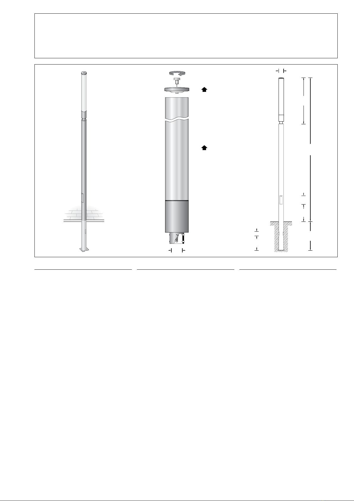
500 × 500
900
1000
befestigte Oberfläche
Paved surface
Surface consolidée
verdichteter Boden
Compacted soil
Sol damé
Erdreich · Soil · Terre
Sauberkeitsschicht
Sub-base
Couche d’assainissement
Drainage · Drainage · Drainage
Beton · Concrete · Béton
Montage Mast:
Für den elektrischen Anschluss der Leuchte ist
eine Kabellänge von ca. 1m über Oberkante
Bodenbelag ausreichend.
Die Schutzschicht im Bereich des Erdstückes
darf nicht beschädigt werden.
Zweiteilige Grundplatte aus dem Mastrohr
entnehmen und am Mast befestigen. Die
Fundamentgröße ist abhängig von der
Topographie, Bodenbeschaffenheit und
Windbelastung und muss jeweils bauseits
bestimmt werden. Dazu gelten die Normen
DIN EN 50 341 und DIN 1045.
Die obige beispielhafte Fundamentempfehlung
gilt nur für einen tragfähigen Baugrund und
nur für das Lichtbauelement 84 992. Tür
mit beiliegendem Vierkantschlüssel öffnen
und entnehmen. Erdkabel durch seitliche
Kabeleinführung in den Mast führen. Leuchte
standsicher gründen.
Installation pole:
For the electrical connection a cable length
of approx. 1m above mounting surface is
sufcient.
The protective coating at the anchorage unit
must not be damaged.
Remove the two-part ground plate from the
pole tube and x it at the pole. The size of
the foundation depends on the topography,
condition of the soil and the wind load and
must be determined on site. The norms
DIN EN 50 341 and DIN 1045 apply.
The above exemplary recommendation for
a foundation is only applicable for a stable
subgrade and for the light building element
84 992 only. Open door with enclosed square
spanner and remove door. Lead underground
cable into the pole through the lateral cable
entry. Set luminaire in a stable foundation.
Installation du mât :
Pour le raccordement électrique du luminaire
une longueur de câble d'environ 1m au-
dessus du bord supérieur de la couche de
nition du sol est sufsante.
La couche protectrice de la pièce à enterrer ne
doit pas être endommagée.
Retirer du mât la plaque de stabilisation se
composant de deux pièces. La xer au mât
à l’aide des vis fournies. Le volume et les
dimensions du massif béton dépendent de
la topographie, la pression à fond de fouille
du sol, de la zone de vent, ainsi que des
forces et des charges exercées et doivent
être individuellement dénis sur le chantier. Se
rapporter pour cela exclusivement aux normes
DIN EN 50341 et DIN 1045.
Le massif de fondation recommandé ci-dessus
est un exemple uniquement valable pour un
terrain à bâtir solide et uniquement pour le
luminaire 84 992. Déverrouiller et retirer la porte
avec la clé jointe. Introduire le câble réseau
dans le mât par l’entrée de câble latérale. Fixer
le luminaire fermement dans la fondation.
Leuchtenmontage:
Bitte beachten Sie:
Für den Austausch des LED-Moduls und
Wechsel der Kunststoffabdeckung ist oberhalb
der Leuchte ein freier Raum von 1300mm
erforderlich.
Verbindungsleitung in Mast einführen und
Leuchtenmuffe auf Mastzopf befestigen.
Anzugsdrehmoment = 12 Nm.
Anschlusskasten öffnen.
Erdkabel in den Anschlusskasten führen.
Schutzleiterverbindung herstellen und
elektrischen Anschluss vornehmen.
Leuchtenanschlussleitung im Anschlusskasten
anschließen.
Auf richtige Belegung der Anschlussleitung
achten. Den Netzanschluss an der braunen
(L), blauen (N) und grün-gelben Ader (1)
vornehmen.
Der Anschluss der Steuerleitungen erfolgt über
die beiden mit DALI gekennzeichneten Adern.
Bei Nichtbelegung dieser Adern wird die
Leuchte mit voller Lichtleistung betrieben.
Anschlusskasten schließen.
Tür einsetzen und verriegeln.
Installation of the luminaire:
Please note:
1300mm space above the luminaire is required
for replacement the LED module and to change
the synthetic diffuser.
Lead the connecting cable into the pole.
Place luminaire on top of the pole.
Fix the luminaire with screws.
Torque = 12 Nm.
Open the connection box.
Lead the mains supply cable into the
connection box. Make earth conductor
connection and electrical connection.
Connect luminaire connection cable in the
connection box.
Note correct conguration of the mains supply
cable. Make mains supply connection at the
brown (L), blue (N) and green-yellow lead
(1). The connection of the control cables is
achieved by means of the both leads marked
with DALI.
In case these leads are not used the luminaire
will be operated at full light output.
Close the connection box.
Install the door and lock it.
Installation du luminaire :
Attention :
Pour le changement de l'élément LED et de
la vasque synthétique prévoir un espace de
1300mm au-dessus du luminaire.
Introduire le câble d’alimentation dans
l’ouverture au sommet du mât et xer le
luminaire sur le mât.
Moment de serrage = 12 Nm.
Ouvrir la boîte de connexion.
Introduire le câble réseau dans la boîte de
connexion à travers l’entrée de câble. Mettre à
la terre et procéder au raccordement électrique.
Raccorder le câble d’alimentation dans la boîte
de connexion.
Veiller au bon adressage du câble de
raccordement. Effectuer le raccordement
électrique au l marron (L), bleu (N) et vert-
jaune (1).
Le raccordement des câbles de la commande
est éffectué avec les ls marqués DALI.
Si ces ls ne sont pas raccordés le luminaire
fonctionne sur la puissance maximale.
Fermer la boîte de connexion.
Installer et fermer la porte.
BEGA Gantenbrink-Leuchten KG · Postfach 31 60 · 58689 Menden · info@bega.com · www.bega.com
4/4
Austausch des LED-Moduls
Die Bezeichnung des LED-Moduls ist auf einem
Etikett in der Leuchte vermerkt.
BEGA Ersatzmodule entsprechen in
Lichtfarbe und Lichtleistung den ursprünglich
verbauten Modulen. Der Austausch kann mit
handelsüblichem Werkzeug durch qualizierte
Personen erfolgen.
Anlage spannungsfrei schalten.
Zum Reinigen der Leuchte nur
lösungsmittelfreie Reinigungsmittel und keine
Hochdruckreiniger verwenden.
Zum Öffnen der Leuchte
Innensechskantschraube (SW 10) im
Leuchtenoberteil lösen und Leuchtenoberteil
abnehmen.
Kunststoffzylinder senkrecht abheben.
Bitte beachten Sie die Montageanleitung des
LED-Moduls.
Dichtungen überprüfen, ggf. ersetzen.
Kunststoffzylinder über die Lampen führen,
Dach mit Dichtungsteller aufschrauben und
mit zentraler Verschraubung bis auf Anschlag
verschrauben.
Anzugsdrehmoment = 16 Nm.
Dabei auf richtigen Sitz der Dichtung achten.
Replacing the LED module
The designation of the LED module is noted on
a label in the luminaire.
The light colour and light output of BEGA
replacement modules correspond to those
of the modules originally tted. The module
can be replaced by qualied persons using
standard tools.
Disconnect the electrical installation.
Use only solvent-free cleansers for cleaning the
luminaire.
For cleaning do not use a high pressure
cleaner.
To open the luminaire undo the hexagon socket
head screw (wrench size 10) in the covering
cap and remove covering cap.
Lift plastic cylinder vertically.
Please follow the installation instructions for the
LED module.
Check gaskets and replace if necessary.
Slide plastic cylinder over the lamps, screw
on luminaire roof with gasket plate and bolt it
together with central screw connection as far
as it will go.
Torque = 16 Nm.
Make sure that gasket is positioned correctly.
Remplacement du module LED
La désignation du module LED est inscrite sur
une étiquette apposée sur le luminaire.
Les modules de rechange BEGA
correspondent aux modules d’origine en
termes de couleur de lumière et de ux
lumineux. Le module LED peut être remplacé
par une personne qualiée à l’aide d’outils
disponibles dans le commerce.
Travailler hors tension.
Pour le nettoyage du luminaire n'utilliser
que des produits de nettoyage ne contenant
pas de solvant et ne pas utiliser de
nettoyeur haute pression.
Pour ouvrir le luminaire desserrer les vis à
six pans creux (taille de clé 10) et retirer le
couvercle de fermeture.
Soulever verticalement le cylindre synthétique.
Respecter la che d’utilisation du module LED.
Vérier les joints, le cas échéant les remplacer.
Installer le cylindre synthétique sur les lampes
et visser le couvercle en contentant le disque
du joint et visser avec la fermeture centrale
jusqu'à la butée.
Moment de serrage = 16 Nm.
Veiller au bon emplacement du joint.
Ersatzteile
Kunststoffzylinder 15 000 319 .6
LED-Netzteil DEV-0356/1400
LED-Modul 3000 K LED-0701/830
LED-Modul 4000 K LED-0701/840
Dichtung Glas oben 83 000 972
Dichtung Dachverschraubung 83 000 981
Dichtung Glas unten 83 001 074
Spares
Synthetic cylinder 15 000 319 .6
LED power supply unit DEV-0356/1400
LED module 3000 K LED-0701/830
LED module 4000 K LED-0701/840
Gasket glass top 83 000 972
Gasket screw connection roof 83000 981
Gasket glass bottom 83 001 074
Pièces de rechange
Cylindre synthétique 15 000 319 .6
Bloc d’alimentation LED DEV-0356/1400
Module LED 3000 K LED-0701/830
Module LED 4000 K LED-0701/840
Joint du verre supérieur 83 000 972
Joint de la fermeture du couvercle 83 000 981
Joint du verre supérieur 83 001 074

This manual suits for next models

2

Other BEGA Outdoor Light manuals

BEGA 84 253 Manual

BEGA

BEGA 84 253 Manual

BEGA 88 214 User manual

BEGA

BEGA 88 214 User manual

BEGA 22 203 Manual

BEGA

BEGA 22 203 Manual

BEGA 85 046 User manual

BEGA

BEGA 85 046 User manual

BEGA 24 102 Manual

BEGA

BEGA 24 102 Manual

BEGA 84 724 User manual

BEGA

BEGA 84 724 User manual

BEGA 24 011 Manual

BEGA

BEGA 24 011 Manual

BEGA 22 228 Manual

BEGA

BEGA 22 228 Manual

BEGA 7263LED Manual

BEGA

BEGA 7263LED Manual

BEGA 88 674 User manual

BEGA

BEGA 88 674 User manual

BEGA 22 327 User manual

BEGA

BEGA 22 327 User manual

BEGA 84 563 Manual

BEGA

BEGA 84 563 Manual

BEGA 84 700 User manual

BEGA

BEGA 84 700 User manual

BEGA 84292 User manual

BEGA

BEGA 84292 User manual

BEGA 7723 User manual

BEGA

BEGA 7723 User manual

BEGA 67 548.2 User manual

BEGA

BEGA 67 548.2 User manual

BEGA 71 127 Manual

BEGA

BEGA 71 127 Manual

BEGA 44 009 User manual

BEGA

BEGA 44 009 User manual

BEGA 84 315 User manual

BEGA

BEGA 84 315 User manual

BEGA 84 289 Manual

BEGA

BEGA 84 289 Manual

BEGA 33 539 Manual

BEGA

BEGA 33 539 Manual

BEGA 71 126 Manual

BEGA

BEGA 71 126 Manual

BEGA 24 216 Manual

BEGA

BEGA 24 216 Manual

BEGA 24 210 Manual

BEGA

BEGA 24 210 Manual

Popular Outdoor Light manuals by other brands

Defiant 53302161 Use and care guide

Defiant

Defiant 53302161 Use and care guide

Sygonix Trento manual

Sygonix

Sygonix Trento manual

Anslut 004585 operating instructions

Anslut

Anslut 004585 operating instructions

Le Klint SNOWDROP-LK 220 instructions

Le Klint

Le Klint SNOWDROP-LK 220 instructions

Outsunny INbkb050V01 quick start guide

Outsunny

Outsunny INbkb050V01 quick start guide

Bona VIKING D15 quick start guide

Bona

Bona VIKING D15 quick start guide

B-K lighting CO2 STANDARD INSTALLATION

B-K lighting

B-K lighting CO2 STANDARD INSTALLATION

Faro Barcelona OLAN 70269 quick start guide

Faro Barcelona

Faro Barcelona OLAN 70269 quick start guide

Quoizel Reece RCE8407EK installation guide

Quoizel

Quoizel Reece RCE8407EK installation guide

Unilamp XEON Cross installation manual

Unilamp

Unilamp XEON Cross installation manual

Unilamp 5505-0-3-873 Series installation manual

Unilamp

Unilamp 5505-0-3-873 Series installation manual

FLINQ FQC8274 instruction manual

FLINQ

FLINQ FQC8274 instruction manual

Maxim 3044RPOLB installation instructions

Maxim

Maxim 3044RPOLB installation instructions

WE-EF ASP530 LED Installation and maintenance instructions

WE-EF

WE-EF ASP530 LED Installation and maintenance instructions

LIGMAN AA-30186-2-2 installation manual

LIGMAN

LIGMAN AA-30186-2-2 installation manual

IKEA ARSTID manual

IKEA

IKEA ARSTID manual

Saxby Lighting 1818PIR Instruction leaflet

Saxby Lighting

Saxby Lighting 1818PIR Instruction leaflet

Feiss OL13500 installation instructions

Feiss

Feiss OL13500 installation instructions

manuals.online logo
manuals.online logoBrands
  • About & Mission
  • Contact us
  • Privacy Policy
  • Terms and Conditions

Copyright 2025 Manuals.Online. All Rights Reserved.