Ewert Energy Systems Orion Jr. 2 BMS User manual

www.orionbms.com
Orion Jr. 2 BMS Operation Manual
The Orion Jr. 2 BMS by Ewert Energy Systems is designed to manage and protect lithium ion
battery packs up to 48v nominal (maximum voltage never to exceed 60V at any time). The Orion Jr. 2
BMS is built on the same technology as the standard Orion BMS product line, but it is smaller and
lighter and is specifically designed with features for stationary and light mobile applications such as
solar & wind storage, UPS systems, golf carts, forklifts, scooters and more.

Orion Jr. 2 BMS Operation Manual
2
Document Revision: 1.0
Last Updated: 8/30/2018
Table of Contents
Overview of Theory of Operation........................................................................................................ 3
Setting up the BMS.............................................................................................................................. 4
Wiring..............................................................................................................................................................................4
Software..........................................................................................................................................................................4
Testing.............................................................................................................................................................................4
How the Orion Jr. 2 BMS Works.......................................................................................................... 5
Changing and Uploading Settings...................................................................................................................................5
Basic Data Collection......................................................................................................................................................5
CHARGE and READY Modes.........................................................................................................................................7
Charge and Discharge Current Limits.............................................................................................................................7
How the BMS Calculates Current Limits.........................................................................................................................8
Selecting Current Limit Settings....................................................................................................................................10
State of Charge Calculation..........................................................................................................................................11
Why SOC Correction Drifts Happen..............................................................................................................................12
Determining State of Charge Correction Drift Points.....................................................................................................13
State of Health Calculation............................................................................................................................................15
Internal Resistance .......................................................................................................................................................15
How the BMS Calculates Internal Resistance...............................................................................................................16
Determining Nominal Resistance..................................................................................................................................17
Controlling Loads and Chargers ...................................................................................................................................18
Digital On/Off Outputs (Relay Outputs).........................................................................................................................18
Watchdog Circuit...........................................................................................................................................................25
CANBUS Communication .............................................................................................................................................25
Analog 5v Outputs.........................................................................................................................................................25
How Balancing Works...................................................................................................................................................26
Open Wire Fault Detection Circuit.................................................................................................................................29
Busbar Compensation...................................................................................................................................................30
Thermal Management and Fan Controller ....................................................................................................................32
Multi-Purpose Input.......................................................................................................................................................33
Multi-Purpose Output ....................................................................................................................................................34
Collected Statistics (Cell Warranty Data) ......................................................................................................................35
Failure Mitigation............................................................................................................................... 37
Understanding Failure Modes.......................................................................................................................................41
Diagnostic Trouble Codes................................................................................................................. 42

Orion Jr. 2 BMS Operation Manual
3
Document Revision: 1.0
Last Updated: 8/30/2018
Overview of Theory of Operation
The Orion Jr. 2 BMS protects and monitors a battery pack by monitoring sensors and using outputs to
control charge and discharge into the battery. The BMS measures inputs from cell voltage taps, a hall
effect current sensor, three thermistors, and a multi-purpose input. Using the programmed settings, the
BMS then controls the flow of current into and out of the battery pack through broadcasting charge and
discharge current limits via the CAN bus, analog reference voltages, or simple on/off digital signals de-
pending on which style is appropriate for the application. The BMS relies on the user to integrate the
BMS with other external devices in a manner such that the current limits set by the BMS are respected
in order to protect the batteries. During and immediately after charging, the BMS will balance the cells
using internal shunt resistors based on the programmed settings.
The Orion Jr. 2 BMS unit monitors the voltage of each individual cell (through the cell tap wires) to en-
sure cell voltages remain within a specified range. Using the collected information, which includes pa-
rameters such as minimum and maximum cell voltages, temperature, and state of charge, the BMS
calculates amperage limits for both charge and discharge. These charge and discharge current limits
are then transmitted to other external devices digitally via CANBUS, via 0 to 5 volt analog signals, or via
on/off outputs. The BMS also calculates the state of charge of the battery pack and monitors the state
of health of the individual cells and battery pack.

Orion Jr. 2 BMS Operation Manual
4
Document Revision: 1.0
Last Updated: 8/30/2018
Setting up the BMS
Wiring
Please see the wiring manual for information regarding wiring the BMS into the application. The wiring
manual can be downloaded from www.orionbms.com/downloads.
Software
Please see the software manual for information on setting up specific software parameters and battery
profile information. The BMS must be connected to a personal computer using the RS-232 serial inter-
face (CAN enabled units may use a CANdapter CAN to USB adapter) and programmed using the Orion
Jr. 2 BMS software utility before it can be used. The settings profile must be setup correctly for the spe-
cific battery used and the application. The settings profile controls parameters such as maximum and
minimum cell voltages and external interfaces such as CAN interfaces and digital I/O. The software and
software manual can be found at www.orionbms.com/downloads.
Testing
After setting up the BMS or making any changes to the BMS settings or external hardware, the entire
setup should be tested to ensure that it is functioning properly. This is particularly important with re-
spect to any potentially catastrophic failures, such as failures that would lead to over charge or over
discharge. It is the responsibility of the user to verify that the BMS is programmed and operating cor-
rectly with the application. At a minimum, the user should perform testing to ensure the following condi-
tions are working properly:
1. Ensure that the BMS is setup in such a manner than testing will not cause immediate danger to
the battery pack.
2. Ensure that cell voltages are being read correctly and that no critical fault codes are present.
The BMS cannot properly read cell voltages if unit and batteries are not wired correctly. Double
checking cell voltages with a multimeter will help verify that the BMS is measuring voltages cor-
rectly.
3. Ensure that the current sensor is reading the correct values and that current going into the bat-
tery pack (charge) shows up as negative and that current leaving the battery pack (discharge)
shows up as positive.
4. If the charge enable, discharge enable, or charge safety outputs are used (physically or trans-
mitted digitally), ensure that they are operating by carefully monitoring the battery pack during
the first full cycle (full charge and discharge) to check that cutoffs are properly working for all
used outputs. Keep in mind that conditions are usually only triggered when the pack is totally
charged or totally discharged. Particular attention should be paid to make sure the BMS is able
to properly shut off any connected battery charger or any other source or load.
5. If charge and discharge limits are used (either via CAN or analog outputs) ensure that they be-
have as expected over the first full charge and discharge cycle and that any devices that must
enforce those limits are actually respecting them.

Orion Jr. 2 BMS Operation Manual
5
Document Revision: 1.0
Last Updated: 8/30/2018
How the Orion Jr. 2 BMS Works
(Detailed Theory of Operation)
Changing and Uploading Settings
The Orion Jr. 2 BMS must be programmed in order to operate. A complete set of settings is called a
pro-file. Settings are edited on a personal computer using the Orion Jr. 2 BMS Utility software and then
are “uploaded” to the BMS via RS-232 serial (or via CANBUS). Profiles can optionally be locked into
the BMS with a password to prevent end users from modifying or viewing settings. Uploading and
downloading settings is normally done over the RS-232 serial interface. If using a computer which does
not have a native RS-232 serial port, a serial to USB adapter may be needed (not sold by Ewert
Energy). Programming over the CANBUS requires a CANBUS enabled Orion Jr. 2 BMS and the use of
a CANdapter (a CAN to USB adapter) sold separately by Ewert Energy Systems. Setting profiles can
also be downloaded from the BMS into the BMS utility to be edited on a personal computer
Basic Data Collection
The Orion Jr. 2 BMS collects data from several different sensors for use in calculations and decision
making.
Cell Voltages - First and foremost, each cell’s voltage is measured approximately every 30 mS by
sensing the voltage at the cell voltage tap connector. The BMS measures the difference in voltage from
one tap wire to the next to measure a cell's voltage. Unless busbar compensation has been configured,
the BMS will display and use the actual measured values for cell voltages (otherwise compensated
values are used). Only the cell voltages which the BMS has been programmed to monitor in the cell
population table in the settings profile are monitored while the other cell voltages are ignored.
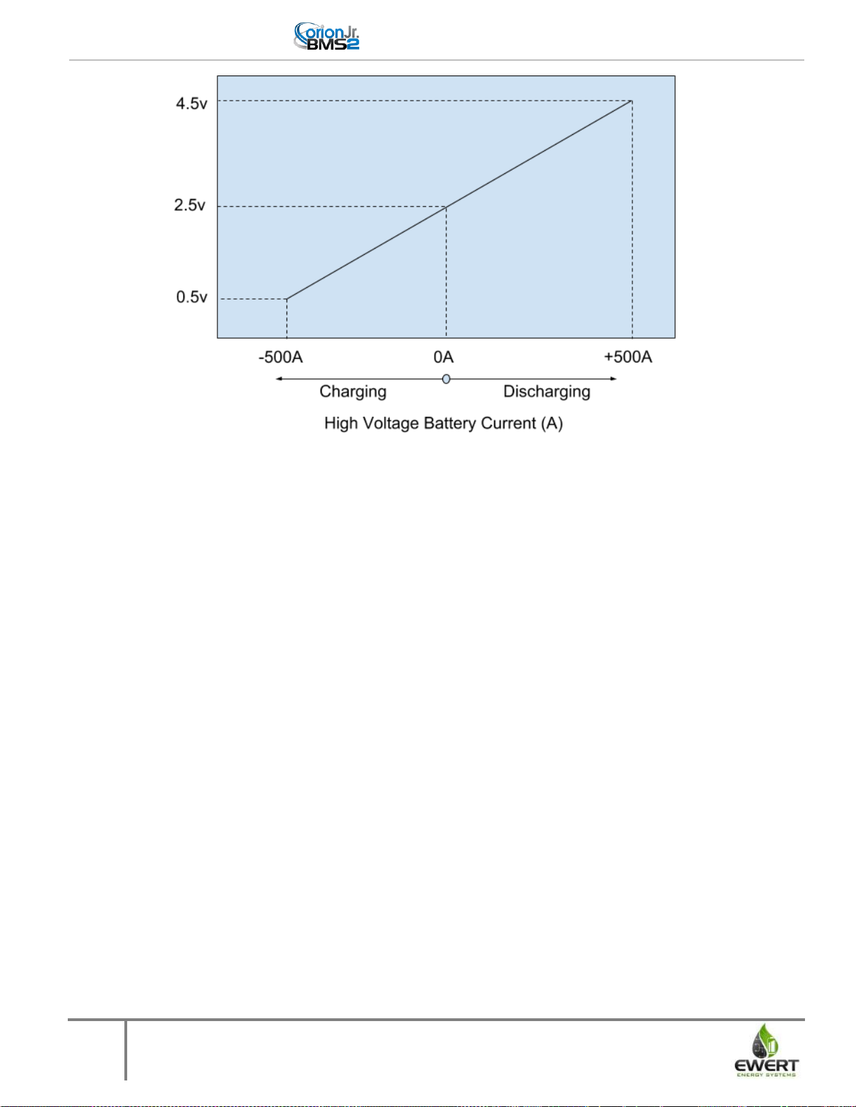
Current (Amperage) - The current going in and out of the battery pack is measured every 8mS using
the external hall effect sensor. The hall effect sensor is clamped around a wire carrying all current into
and out of the battery pack and converts the measured amperage into two 0 - 5 volt analog voltages.
One channel is used for measuring smaller amperages to ensure high resolution for small currents and
the other channel is used for measuring larger currents. These two analog voltages are measured by
the BMS and converted into an amperage value which the BMS uses for various calculations. The
diagram below demonstrates how the feedback voltage from the larger channel correlates with the
actual current being measured (a 500A sensor is used for demonstration purposes).
Orion Jr. 2 BMS Operation Manual
6
Document Revision: 1.0
Last Updated: 8/30/2018
This figure demonstrates the relationship between the voltage output and current measured on the current sensor
The currents sensors sold with the Orion Jr. 2 BMS are available in sizes up to 1000A. The BMS can
be configured to use 2 parallel current sensors to measure amperages up to 2000A, however the max-
imum recommended size is 1000A. Current sensors sold with the BMS are able to measure amperages
up to 120% of their rated maximum, though accuracy is reduced above 100%.
Current sensor data is used in calculating the battery pack’s state of charge (via coulomb counting) and
ensuring that the attached application is staying within the correct current limits. The measured current
is also used in calculating the internal resistance and health of the cells in the battery pack.
Temperatures - The BMS measures battery temperatures directly from up to 3 thermistors to
determine the average temperature of the battery pack. If additional temperature sensing, such as
measuring the temperature of each individual cell, is required, the Orion Jr. 2 BMS can be connected to
a thermistor expansion module which can allow measuring up to 80 thermistors. Thermistors on both
the main unit and any expansion modules may be left ‘unpopulated’ meaning that the BMS will ignore
the value of those thermistors. This allows the BMS to be configured to use as few or as many
thermistors as necessary. The thermistor expansion module is connected to the Orion Jr. 2 BMS
through two of the analog thermistor inputs on the BMS or via CANBUS if the BMS is CAN enabled.
Total Pack Voltage - The Orion Jr. 2 BMS measures the total pack voltage by summing up the
individual cell voltages.
Other Inputs - The BMS has the ability to sense the status of the CHARGE power supply. The BMS
uses this input to determine what mode the BMS is in. The BMS also has a multi-purpose input which
can be used for various functions, including monitoring the status of the READY power source if
necessary.

Orion Jr. 2 BMS Operation Manual
7
Document Revision: 1.0
Last Updated: 8/30/2018
CHARGE and READY Modes
The BMS has two modes of operation: charge mode and ready mode. The BMS will enter into charge
mode any time > 9V is applied to the CHARGE power pin, regardless of whether READY power is also
present or not. The following functions are enabled (or change) when the BMS is in CHARGE mode:
1. The charger safety output is allowed to turn on if enabled and if all criteria have been met.
2. The BMS will cap the state of charge to the value specified as the "Charged SOC" percentage.
Even if the battery is charged in such a way that would normally cause the SOC to rise above
this value, the value will not exceed the "Charged SOC parameter" while the BMS is in charge
mode.
3. When any cell voltage reaches the maximum cell voltage (resulting in the BMS turning the
charger off), the BMS will immediately adjust the state of charge to the "Charged SOC" value
since the BMS knows that the battery pack is fully charged at this time.
4. The cell balancing algorithm is enabled and will begin balancing as soon as any cell voltage
goes above the "Start Balancing" voltage. Balancing will continue until all cell voltages are bal-
anced to within the balance delta voltage parameter. See the “How Balancing Works” section for
more information on cell balancing.
5. The maximum possible current limit for charging is limited to "Maximum Amperage While Charg-
ing."
6. The maximum allowable cell voltage is limited to the "Max. Voltage While Charging" parameter.
Charge and Discharge Current Limits
For Lithium-ion cells, limiting cell voltages to within a specified voltage range is essential for protecting
the cell from damage. However, there are many other parameters, such as temperature and current
limits, which must also be monitored to protect the cells. To be able to control more than one parameter
at once, the BMS incorporates different parameters into a maximum allowable charge and discharge
current limit. Charge and discharge limits can be thought of as the realistic maximum amperage limits
that a battery can discharge or charge at any given moment (expressed in 1 amp increments). Current
limits are especially useful for variable current applications such as light mobile applications, because
they allow these applications to slowly reduce current as a battery pack is emptied and therefore in-
crease the usable range of a battery pack.
The charge and discharge current limits can be transmitted digitally from the BMS to other devices if
the external device supports this. For example, most CANBUS enabled motor controllers and CANBUS
enabled battery chargers support this. When a motor controller receives the current limit from the BMS,
the motor controller knows that it cannot exceed the maximum current limit sent by the BMS even if the
operator of the throttle calls for more power. Because the BMS incorporates many factors into the max-
imum current limit, ensuring the current does not exceed this calculated current limit also ensures all
the other associated battery parameters (such as minimum cell voltage, temperature, maximum C rate,
minimum state of charge, etc) are enforced.
While some motor controllers or chargers don’t support CANBUS, they may support an analog voltage
input that represents the current limit. The Orion Jr. 2 BMS has 0 to 5 volt analog outputs which repre-

Orion Jr. 2 BMS Operation Manual
8
Document Revision: 1.0
Last Updated: 8/30/2018
sent the maximum current limits in an analog voltage. This operates the same way as the CANBUS
support, but is less accurate and less desirable than CANBUS control. If the 0 to 5 volt analog outputs
are used, it is essential to ensure that the BMS and the external device share the same ground and that
they are used in conjunction with the charge enable, discharge enable, or charger safety outputs de-
pending on the exact use.
When a load does not support variable current limiting and can only be turned fully on or fully off (such
as a DC to AC inverter), the BMS must operate in an on/off mode to control the load. In this case, the
BMS still uses the charge and discharge current limits as the basis for making decisions about when
the BMS will allow charge or discharge. The relay outputs will turn off whenever the associated current
limit drops to 0 amps at any point. The BMS’s decision whether to allow charge or discharge is availa-
ble on the CANBUS and also on the charge enable and discharge enable outputs. The exact conditions
for this are discussed in the Relays section of this manual.
How the BMS Calculates Current Limits
The charge and discharge limits are both calculated using the same methodology. The charge current
limit takes into account the settings and parameters related to charging and the discharge takes into
account the settings and parameters related to discharging. For simplicity, all criteria described below
are for the discharge current limit. However, the same methodology applies to the charge current limit.
The BMS starts the current calculation by loading the maximum continuous discharge current limit pro-
grammed into the BMS. This setting is the maximum continuous discharge rating that the cell can sus-
tain safely. The maximum current a cell can discharge is defined by the cell manufacturer, and the val-
ue in the BMS should never exceed the maximum limit given by the cell manufacturer, though in some
cases, it may be desirable to use a lower value than specified by the cell manufacturer for increasing
the lifespan of the cells.
The above calculations establish the absolute maximum allowable current under ideal conditions. How-
ever, the BMS may reduce those limits further for several reasons. If any of the below calculations re-
sult in a calculated current limit lower than the absolute maximum, the BMS will use the lowest of the
calculated limits as the current limit.
1. Temperature - The BMS will lower the current limits based on the temperature limitations pro-
grammed into the BMS profile. The temperature limits are set by specifying a minimum and
maximum temperature to start de-rating current and then a number of amps per degree Celsius
to de-rate by when the temperature is outside of this range. Minimum and maximum battery op-
erating temperatures for cells are enforced by ensuring that the current limits are reduced to 0
amps at the minimum and maximum temperatures. Ensuring temperature limits are 0 amps at
the minimum and maximum temperatures also ensures that under all situations the charge ena-
ble, discharge enable, and charger safety enable outputs are all off if a thermistor ever exceeds
a maximum temperature or a minimum temperature. (Note: an exception is if a thermistor reads
a value less than -41C or greater than 81C at which point the BMS will disregard the value of
the thermistor as faulty.)
2. State of Charge - The BMS will lower the current limits based on the calculated state of charge
of the battery pack. Just like the temperature settings above, the BMS can optionally reduce the
maximum current limits based on the programmed values in the profile settings. In this case, for

Orion Jr. 2 BMS Operation Manual
9
Document Revision: 1.0
Last Updated: 8/30/2018
the discharge current limit, a state of charge is specified where to begin reducing the discharge
current limit along with a value of amps per percentage state of charge. For most applications,
this feature is not used and should be disabled to prevent errant SOC calculations from altering
the usable range of the pack unless there is a specific reason for enabling it. This feature may
be required, however, if the battery pack must be kept within a certain state of charge.
3. Cell Resistance - The BMS reduces the current limit to ensure that, if a load or charge is
placed on the battery pack, the load or charge would not cause the cell to exceed the maximum
cell voltage or drop below the minimum cell voltage. This calculation uses the internal resistance
of the cell and the open circuit voltage of the cell. This can be thought of as an ohm’s law
calculation where the BMS is solving for the maximum possible amperage that will still keep the
cell voltage inside the safe range. This calculation preemptively keeps the cell voltage within
specifications and also results in a 0 amperage discharge or charge current limit in the event a
cell voltage drops below the minimum or goes above the maximum voltage respectively.
4. Pack resistance - If enabled, the BMS performs the same calculations as in point 3, but for the
minimum and maximum pack voltages and reduces current limits to maintain these values.
5. Cell Voltage - In the event that the above calculation were to ever be inaccurate due to incor-
rect data such as an incorrect cell resistance or incorrect open circuit, or if the current limit is ig-
nored by the external device, the BMS contains a backup algorithm for reducing the current lim-
its if a cell voltage limit is exceeded. If the BMS measures a cell voltage above the defined max-
imum cell voltage or below the defined minimum cell voltage, the BMS will cut the respective
current limit by one fifth of the current limit at the time the out of range cell voltage is measured
in an attempt to restore the voltage to a safe level. If this fails to bring the cell voltage back to
within the defined range, the BMS will again cut the current limit by one fifth of the maximum
continuous amperage and try again. This will happen very rapidly up to a total of five times. If
the voltage is still outside of the range, the BMS will have reduced the current limit to zero amps
which prohibits all discharge or charge (depending on if the cell voltage was too low or too high
respectively.) This ensures that under all circumstances, if a cell voltage is ever above the max-
imum limit or below the minimum limit, the BMS will always have a zero amp charge or dis-
charge current limit which prohibits all charge or all discharge respectively. This ensures that the
charge enable, discharge enable and charger safety enable outputs are all off if a cell ever ex-
ceeds a maximum cell voltage or drops below a minimum cell voltage.
6. Pack Voltage - If enabled, the BMS performs the same calculations as in part 5, using the pack
voltage limits rather than the cell voltage limits. Total pack voltages are calculated based on the
sum of the individual cells. For best reliability, pack voltage limiting should only be used when it
is necessary to restrict the pack voltage more than the individual cell voltage restricts the pack
voltages. For example, if a pack has 10 cells and the cell voltage limits are 2.5v and 3.65v, the
pack voltage is already inherently limited to 25v to 36.5v.
7. Critical Faults - In the event that the BMS detects a critical fault relating to the ability of the
BMS to monitor cell voltages, the BMS will go into a voltage failsafe condition. The specific pos-
sible causes of the voltage failsafe mode are defined in the “Understanding Failure Modes” of
this manual. If one of the critical faults that cause a voltage failsafe condition occurs, the BMS
will immediately start gradually reducing both the charge and discharge current limits to zero
which prohibits all charge and discharge. The gradual reduction allows a vehicle time to pull
over and safely stop. The speed at which the limits are reduced is programmable in the BMS
settings. The relay outputs will be turned off only after the gradual de-rating has occurred.

Orion Jr. 2 BMS Operation Manual
10
Document Revision: 1.0
Last Updated: 8/30/2018
Diagnostic information is provided from the BMS in the live text data tab in the utility as to which of the
above reasons the BMS is limiting current.
Selecting Current Limit Settings
The Orion Jr. 2 BMS utility has data for many common cell types already pre-loaded into the utility.
These can be accessed by using the Profile Setup Wizard in the BMS utility. For cells which are not
listed, or if custom settings are required, the following guidelines may be helpful for selecting proper
values.
Maximum Continuous Amperage Setting - The continuous maximum amperage should be set at or
below the maximum allowable continuous amperage as specified by the cell manufacturer. In some
cases, it is desirable to use a lower value than what the manufacturer specifies in order to extend the
lifespan of the cells. In some cases the manufacturer will specify a “C” rate. To convert a “C” rate to an
amperage, simply multiply the C rate by the amp hour capacity of the cell. For example, a 100 amp
hour cell with a 2C continuous discharge rating is has a maximum continuous discharge rate of 200
amps.
Current Limit Temperature Settings - All cell manufacturers specify a minimum and maximum oper-
ating temperature for charge and discharge. Typically, the temperature range for charging is more re-
strictive than the temperature for discharging. Some cells are not permitted to be charged below a cer-
tain temperature. For example, many iron phosphate cells cannot be safely charged below freezing.
Additionally, it may be desirable to further limit the amperage at low or elevated temperatures since
high charge and discharge rates at such temperatures may reduce the lifespan of the cells.
Temperature limits must ensure that no charge or discharge is permitted below the minimum or above
the maximum temperatures. For both charge and discharge settings, select a temperature at which the
maximum amperage should be reduced. This value should be programmed into the BMS utility, and an
amps per degree Celsius value should be calculated to ensure that the slope of the line intercepts zero
amps at the desired cutoff temperature. This should be done for both high and low temperature limits
for both charge and discharge current limits. Warning: If the temperature de-rating line does not inter-
cept zero, the BMS will not protect for over or under temperature!
In a very limited number of applications, it may be necessary to allow a minimum charge or discharge
value at all temperatures. If this is the case, the “Never reduce limit below xx amps for temperature
alone” setting can be used. Warning: if the “never reduce limit below” setting is anything other than ze-
ro, the BMS will not protect for over or under temperature!
Note: While the maximum amperage can be specified for a specific temperature, the BMS may still use
a lower current limit if it determines a cell resistance cannot support a current limit. Most lithium ion
cells have a significantly higher resistance in the cold and may be limited by cell performance rather
than by these settings.
State of Charge Current Limit Settings - These settings allow the BMS to gradually reduce the
maximum allowable amperage based on the calculated state of charge of the battery pack. If this

Orion Jr. 2 BMS Operation Manual
11
Document Revision: 1.0
Last Updated: 8/30/2018
line intercepts zero amps, the BMS will prohibit all charge or prohibit all discharge if the SOC is
higher or lower respectively than the state of charge where the line intercepts zero amps.
While this feature can be helpful for certain applications, it should be left disabled when not required.
State of charge of the battery is calculated by the BMS. It is possible for this calculation to become in-
accurate for a variety of reasons, such as a current sensor fault, incorrectly set SOC drift points, a low
capacity cell, or if the BMS memory has been reset since the last full charge or discharge. If this feature
is used, care must be taken to ensure that the SOC drift points are setup correctly and that the applica-
tion will operate safely and appropriately in the event that the SOC calculation becomes inaccurate.
Other related settings - Cell resistance settings are not directly related to the current limits, but they
can impact the current limits. The nominal cell resistances are loaded into the BMS when it first turns
on and are used initially for the cell resistance current limit calculation. The BMS will switch to using
measured cell resistances as soon as that information is available, but current limits may be incorrect
when the BMS is first turned on if the default resistance settings are incorrect.
State of Charge Calculation
Note: The Orion Jr. 2 BMS cannot calculate state of charge without a current sensor!
The Orion Jr. 2 BMS calculates a battery pack’s state of charge (SOC) primarily by coulomb counting,
or by keeping track of how much current has entered or left the battery pack. This method requires the
use of a current sensor and generally tracks the state of charge of the battery pack quite well provided
that the capacity of the battery is known and the current sensor is accurate. While coulomb counting is
an accurate method, there are several things that can cause this calculation to become inaccurate.
These things include inaccurate current sensors, cells with a different capacity than expected (e.g. from
low temperature or weak cells), or the BMS memory being reset or reprogrammed.
To deal with these issues, the BMS has an SOC correction algorithm which compares measured open
circuit cell voltages to known state of charge points. These points are called “drift points” and are pro-
grammed into the BMS when it is setup. Drift points are specific voltages that are known to correlate to
a specific state of charge and will vary from chemistry to chemistry. If the open circuit cell voltage is
measured to be at one of these specific “drift points,” the BMS knows what the state of charge of the
battery is supposed to be. In the event that the BMS’s calculated state of charge is higher or lower at
one of these points, the BMS will adjust the calculated state of charge to the correct value.
Drift points are usually selected at locations along the cell’s discharge graph where the cell’s state of
charge is obvious in a manner to avoid drifting incorrectly. For iron-phosphate cells, this means that re-
ally only the upper 10-15% and lower 10-15% of the cell can be used for drift points due to the flat
shape of the discharge curve. For other chemistries, additional points throughout the full range of state
of charge may be possible, improving the accuracy of the drifting.
Drift points are specified to only drift up or only drift down. The BMS will always uses the highest open
circuit cell voltage and lowest open circuit cell voltage for these calculations such that that the pack is
properly protected.

Orion Jr. 2 BMS Operation Manual
12
Document Revision: 1.0
Last Updated: 8/30/2018
In addition to the drift points that are programmed in, the BMS also knows what state of charge the bat-
tery is at when a charge cycle completes. Since the BMS is controlling the battery charger, the BMS will
set the state of charge to the “Charged SOC” value to indicate a full charge whenever it turns the
charger off due to a full charge. It should be noted that this only occurs when the BMS is in CHARGE
mode and actually turns the charger off due to a full charge.
Why SOC Correction Drifts Happen
Correction drifts generally occur for one the following reasons:
1. A drift may occur if one or more cells within the battery pack has a lower capacity than the oth-
ers. The battery pack is only as strong as the weakest cell, because the weakest cell cannot be
over charged or over discharged. If a cell has a lower capacity than the rest of the pack, the
weak cell will cause the BMS to correct the state of charge on the high end or on the bottom end
depending on how the cell is balanced. The 2 images below show a top balanced and bottom
balanced iron phosphate cell. A drift will occur at 100 amp hours in both cases since the weak-
est cell is only 100 amp hours. The remaining 80 amp hours is not usable since one cell’s volt-
age would exceed the allowable range.
2. A drift may occur if the battery pack is out of balance. If one cell is at 70% state of charge, and
another cell is at 30% state of charge, less than 50% of the battery is usable without one of the
cells getting too high on the high end or too low on the low end. This limits the usable range of
the battery and results in a lower capacity than the BMS is expecting, which requires the BMS to
adjust the calculated state of charge. During discharge, as the BMS sees the lowest cell’s open
circuit voltage drop to a known drift point, the BMS will correct the state of charge showing that
the battery is nearly depleted. The same will happen during charge due to a high cell voltage. In
the example below, while the cells are 180 amp hours in size, two cells are 40 amp hours out of
balance with each other and only 100Ah is usable before a cell voltage becomes too high or too
low. In this example, SOC corrections would occur at the both ends of the 100Ah usable range.
This would be due to the blue cell on the high voltage and the red cell at low voltage.

Orion Jr. 2 BMS Operation Manual
13
Document Revision: 1.0
Last Updated: 8/30/2018
3. A correction drift may occur if the capacity of the cells has changed due to cold temperatures.
Some cells (notably iron-phosphate cells) have a restricted range in the cold which can be as lit-
tle as 50% of the normal capacity.
4. A correction drift may occur if the calculated SOC does not actually match the state of charge of
the battery pack, which can be a result of an inaccurate current sensor. This can also happen if
certain settings on the BMS have been changed, if the BMS has been reset by software, or if
the BMS has just been connected to the battery pack for the first time. When the BMS is pow-
ered up for the first time, it will not know the state of charge of the battery pack. In these cases,
the BMS defaults to 50% state of charge, and a state of charge drift is almost certain to occur
within the first cycle to correct the state of charge unless the battery happened to be at exactly
50% state of charge.
5. If the pack capacity is lower than the capacity programmed into the BMS unit.
6. If the minimum and maximum cell voltages are restricting the usable range of the pack and the
SOC settings programmed into the BMS don’t reflect the lower usable range.
7. Inaccurate open circuit voltage calculations due to an incorrectly installed or defective current
sensor.
Note: The Orion Jr. 2 BMS cannot calculate state of charge without a current sensor! If a current sensor
is not connected, the Orion Jr. 2 BMS will derive the state of charge based strictly on instantaneous cell
voltages. This method is very inaccurate - the state of charge calculation may oscillate wildly and
should not be used for any calculations. This mode exists only as a backup algorithm for specific appli-
cations and is not designed for normal use.
Determining State of Charge Correction Drift Points
Every battery chemistry will have different state of charge drift points. Unfortunately, cell manufacturers
typically do not provide this information and it often has to be determined either from experimenting or
from performing careful analysis and running charge and discharge cycles. While the points can be es-
tablished, some tweaking may be required to maximize performance.
Ewert Energy maintains a database of state of charge drift points for many common cell types. This in-
formation can be automatically entered into the battery profile by using the “profile setup wizard” in the
BMS utility. For cells that are not in the database, Ewert Energy offers a service to characterize cells.

Orion Jr. 2 BMS Operation Manual
14
Document Revision: 1.0
Last Updated: 8/30/2018
This service will produce default settings for cell resistance measured at different temperatures, SOC
settings, and standard voltage settings. This service requires at least one sample cell and the manufac-
turer datasheet. For common cells which are not in the database yet, the service may be discounted or
free when a sample is provided.
To determine approximately where the drift points should be, take a sample cell and charge it up to
100% SOC (following manufacturer's recommendations). After the sample cell is fully charged, dis-
charge it to 0% (following manufacturer specs for the minimum cell voltage and discharge rate) at a
very low amperage to get as close to an open cell voltage curve as possible. Once the discharge is
complete, graph the cell voltage vs. amp hours discharged, and there should be a fairly clear discharge
“curve” (can be very different shapes depending on the chemistry.) From this data, approximate SOC to
voltage data can be gathered. Some trial and error may be necessary to fine tune the drift points.
While datasheets from the battery cell manufacturer may be useful in calculating rough drift points, they
often contain graphs with instantaneous voltages at higher C rates which have added voltage drop from
the cell resistance included. The values for SOC drift points are the open circuit voltage (voltage without
a load applied) of a cell.
Drift points should be established at places on the discharge curve where the voltage change is most
significant. For example most iron phosphate cells stay at 3.3v for the majority of the discharge curve
and suddenly start to rapidly drop at 3.0v. 3.0 volts is a good place to set a point. If the drift points are
set too close together (e.g. if a drift point is set at 3.4v and 3.2v and the battery spends most of its time
at 3.30-3.35v) then they may trigger SOC drift prematurely as the open cell voltage of a battery will drift
up and down slightly under load due to a temporary voltage depression (e.g. under a 100A load a bat-
tery’s open cell voltage may drop from 3.3v to 3.2v, though it will gradually return to 3.3v once the load
is removed).
A state of charge drift point consists of two items, an open cell voltage and a corresponding state of
charge percentage. When a cell’s open cell voltage equals the open cell voltage of the programmed
drift point, then the state of charge will drift to the state of charge associated with the programmed drift
point. Additionally, drift points are specified as “drift up only” and “drift down only”, indicating which di-
rection they are allowed to affect drift (e.g. If a drift point at 80% SOC is set to 3.5v and is flagged as
“drift up only”, then it cannot cause the SOC to drift down to 80% if the open cell voltage is below 3.5v).
It is important to have a sufficient number of state of charge drift points to both protect the battery and
to maintain an accurate SOC calculation. Typically at least 4 points are used (2 on the top end and 2 on
the bottom end of the curve) though this is not a minimum. For batteries which do not have a large flat

Orion Jr. 2 BMS Operation Manual
15
Document Revision: 1.0
Last Updated: 8/30/2018
portion of the “curve”, additional points may be used in the middle of the battery for increased accuracy.
Having a correct SOC calculation is important for maintaining the battery in a specified range. However,
regardless of the state of charge calculation, the Orion Jr. BMS can still protect the battery pack from
damage from over-voltage and under-voltage via monitoring the instantaneous cell voltages.
The state of charge drift points in the Orion Jr. 2 BMS are not jump points. This means that when the
open cell voltage on a particular cell reaches a drift point, it will not immediately jump to the provided
state of charge. Rather, it will gradually “drift” up or down until the battery pack state of charge is equal
to the target state of charge. This additional hysteresis helps make the transition smoother as well as
helps eliminate “partial” drifts where the open cell voltage may only very briefly exceed the drift point
voltage.
The BMS allows for State of Charge drift points to be flagged as “Drift Down Only” and “Drift Up Only”.
These are very helpful for situations where a battery’s voltage may not stay constant at a given voltage
for very long. “Drift Down Only” means that the BMS will only allow the given drift point to make the
State of Charge go down (it won’t make the SOC go up if the observed open voltage is higher). Like-
wise, “Drift Up Only” will only allow the SOC to go up and not down.
“Drift Down Only” and “Drift Up Only” are very useful settings for batteries that have a high surface
charge (where the battery voltage may dip to a specific voltage but over time will creep back up). The
use of these settings is recommended for all drift points as most batteries will demonstrate at least
some degree of surface charge.
State of Health Calculation
The Orion Jr. 2 BMS determines the State of Health of the battery pack primarily by examining both the
Internal Resistance and the observed capacity (measured in amp-hours) of the battery pack. As the
observed capacity decreases from the nominal (starting) capacity and the internal resistance increases
from the nominal capacity, the state of health will go down. This value is typically reflective of the age of
the battery pack. However, defective cells or premature aging due to abuse, loose busbars or terminals,
or improper wiring can also cause this calculated value to drop prematurely or incorrectly.
Every application will have different requirements for what state of health is acceptable. For stationary
applications such as a light mobile vehicle, a lower state of health might be acceptable. For an applica-
tion such as an electric vehicle the minimum state of health may higher, so the pack may need replac-
ing sooner than in other applications. A minimum state of health threshold can be programmed into the
BMS. If the state of health drops below this value, a weak pack fault code will get set. This fault code is
informational only to indicate that the battery pack should be inspected and will not alter the behavior of
the BMS in any way. Although the fault does not alter the behavior in any way, a high resistance cell or
a cell with a lower capacity than expected could impact operation in other ways.
Internal Resistance
The Orion Jr. 2 BMS measures the internal resistance of each cell by measuring the relative change in
voltage when a known load is applied to the cell. In order to calculate the internal resistance, the BMS

Orion Jr. 2 BMS Operation Manual
16
Document Revision: 1.0
Last Updated: 8/30/2018
depends on external changes in current. The BMS cannot directly measure the internal resistance
without changes in current being applied to the cells, and if external changes in current are not availa-
ble or not suitable, the BMS may not be able to calculate the resistance of cells. When the BMS is not
able to measure the actual resistance, the nominal resistances programmed into the settings profile are
used until an actual measurement can be obtained.
Internal resistance is the main reason cell voltages change nearly instantly when a load or charge is
applied to the cell. When current is applied to the cell, the resistance inside the cell causes a voltage
drop (or rise) with respect to the amount of current flowing through the cell. When the current stops
flowing through the cell, the voltage will go back to the open circuit voltage. For example, if a battery
has an internal resistance of 2 mOhm (0.002 Ohm) and starts off at 3.3v, the instantaneous cell voltage
will be 3.5v while a 100A charge current is applied (a 0.2v voltage “drop” since 100amps * 0.002ohms =
0.2volts, E = I * R). When the pulse is finished, the instantaneous cell voltage drops back to about 3.3v.
Knowing the internal resistance for each cell allows for the calculation of how much current a cell can
handle before the minimum or maximum cell voltages would be exceeded. This information is also used
in calculating the open circuit voltage of a cell, even when the cell is under load, which is used for state
of charge correction drift points. Cell resistances are also useful for measuring the amount of energy
loss. Internal resistance is often expressed in milliohms (mOhms) or one thousandth of an ohm.
How the BMS Calculates Internal Resistance
The Orion Jr. 2 BMS depends on external changes in current to be able to back calculate the re-
sistance of each individual cell Therefore, the BMS does not initially know the cell resistances and will
begin by using pre-programmed default resistances based on the temperature of the cells. To do this,
the BMS takes the average temperature of the pack and looks up the nominal resistance for the cell for
the average temperature of the pack in the nominal resistance table programmed into the BMS. The
BMS uses the default value until a real measurement can be taken.
Only certain changes in current are used by the BMS for determining internal resistance. The changes
in current must be sudden enough, large enough, and stable enough within a set amount of time for the
BMS to use them in the calculation. A minimum of two changes of current are needed within a set
amount of time for the BMS to update the resistance data. The calculated current trigger is generally a
percentage of the total amount of the current sensor. The minimum value is generally about 20% of the
value of the current sensor, but the minimums are adjusted automatically by the BMS based on other
factors such as temperature as the cell may not be able to output enough power to meet the 20%
standard threshold when cold.
The BMS will prefer to use calculated internal resistance values, but nominal resistance values must be
programmed into the BMS as default values. The default values are used when the BMS is first pow-
ered up or when power has been interrupted to both power sources. Since temperature can significant-
ly alter the internal resistance of a cell, the BMS will also use default values when a significant change
in temperature has occurred since the last known calculated internal resistance value.

Orion Jr. 2 BMS Operation Manual
17
Document Revision: 1.0
Last Updated: 8/30/2018
Determining Nominal Resistance
Internal resistances of cells change considerably based on temperature. Typically a battery will have a
significantly higher resistance in colder temperatures than in hot temperatures. Lithium ion batteries
tend to have an L-shaped resistance curve with the resistance increasing exponentially in cold / freez-
ing temperatures and slowly approaching a lower resistance in extremely hot temperatures.
The Orion Jr. 2 BMS allows the user to specify the nominal resistance for each temperature range in
increments of 5 degrees Celsius. This allows for using any type of different Lithium ion battery regard-
less of how unique its resistance curve is. It is important both for the protection of the batteries as well
as the determination of cell health that these figures be as accurate as possible. Too high internal re-
sistance numbers can cause the initial calculated current limits to be too low and can also cause the
BMS not to set weak cell faults when it should. Internal resistance numbers set too low can result in
false positive “weak cell faults” and the BMS initially calculating that a battery pack can supply a higher
amperage than it actually can (the BMS would update the current limit as soon as current started to
flow).
It is best, however, to test the resistance at least every 10 degree Celsius over the entire usable range
if possible. After a few points are collected at different resistances, an exponential curve should begin
to emerge and in some cases, it may be possible to extrapolate some data without testing at every 5 or
10 degrees Celsius.
Note: Internal resistances will be significantly higher at full state of charge and empty state of charge.
When determining nominal internal resistance values, the resistance should be measured at a normal
state of charge such as around 50%.
Ewert Energy offers a service for measuring internal resistance from sample cells at temperatures
across the working range of the cell and turns this data into settings for the BMS profile. For more in-
formation about this service, please contact Ewert Energy.
To determine the nominal resistance for a battery at a given temperature the following procedure
should be followed:
1. Charge the battery to an appropriate state of charge where the resistance is roughly the nominal
resistance. Most lithium ion cells will have a significantly higher resistance at very high and very
low states of charge and those areas should be avoided for calculations. For best results, repeat
this procedure at several different states of charge.
2. Let the battery sit at the desired temperature for a period of time (can be several hours depend-
ing on the mass of the battery) without any current going in or out (resting).
3. Measure the voltage of the cell very accurately. This will be the Open Cell Voltage of the battery
since there is no current going in or out.
4. Apply a known constant load to the cell.
5. After 10 seconds, take another voltage measurement.
6. Measure the actual amperage leaving the battery to increase the accuracy of the calculation.
7. Subtract the voltage reading from step #5 from the voltage reading from step #2 to get the Volt-
age Drop.
8. Divide the Voltage Drop by the measured amperage from step #5 to determine the 10 second
DC internal resistance (DCIR) expressed in Ohms. (convert to milliohms by dividing by 1,000)

Orion Jr. 2 BMS Operation Manual
18
Document Revision: 1.0
Last Updated: 8/30/2018
Example: Assume a battery is observed at 3.3v resting. A 20 amp load is applied to the battery at which
point the measured voltage drops to 3.0v. The internal resistance can be computed by taking 3.3v -
3.0v = 0.3v / 20 = 0.015 Ohm or 15 mOhm at the specific temperature the reading was taken.
The Orion Jr. BMS itself can be used to perform these calculations when used in a controlled environ-
ment. Using the Orion Jr. BMS to determine internal resistances has the added advantage of being
able to calculate the AC vs. DC internal resistance ratio as well: The same procedure is used above,
but with the BMS measuring the cell voltages and current. Instead of a single 10 second pulse, a 10
second pulse should be applied first, followed by a series of 5 or so quick 1 to 2 second pulses. The
addition of the 1-2 second pulses helps ensure that the BMS is able to accurately calculate the AC in-
ternal resistance. The manually calculated value after 10 seconds is compared to the value that the
BMS calculates after all the pulses are complete. The difference between these two internal resistance
values is the AC vs. DC resistance ratio.
Controlling Loads and Chargers
The Orion Jr. 2 BMS makes decisions about whether or not the battery pack can accept charge or dis-
charge. As the BMS does not have integrated switches or contactors, the BMS unit cannot stop current
flowing in or out of the battery pack by itself. Instead, it provides signals to externally connected devices
instructing them to either turn on and off, and for devices which support it, it provides a maximum al-
lowable current limit. The BMS must be properly integrated with all current sources and loads connect-
ed to the battery being protected. Failure to do this may lead to a battery fire and/or permanently dam-
aged cells.
Devices typically fall under two categories. Devices that can only be turned on or off (such as DC to AC
inverters) and devices which can be variably limited (such as motor controllers or many battery
chargers.) While the BMS may be setup differently depending on which type of device it is controlling,
the methodology for both is based on calculated current limits.
Digital On/Off Outputs (Relay Outputs)
Three on/off outputs are provided on the Orion Jr. BMS for controlling chargers and loads. Conceptually
these outputs can be thought of as whether the BMS is allowing charge or discharge into the battery
pack at any given time. All three outputs are open drain and are active low (pull down up to 175mA to
ground when on). These outputs are on (pull down to ground) when discharging or charging is permit-
ted. For more information on the electrical specifications and wiring procedures for these outputs,
please see the wiring manual.
Each of the on/off relay outputs are designed to control different types of devices. Charge enable and
discharge enable share the same algorithm for turning on and off while charger safety uses a slightly
different algorithm. The discharge enable output is designed to control any load on the battery pack.
Charger safety is designed to control a battery charger when used in a defined charging period where a
user input starts the charging process such as when a vehicle is stopped and plugged in. The charge
enable output is designed to control devices which may alternate between charging and discharging,
such as regenerative braking in a vehicle or solar energy storage applications. It is also used when the

Orion Jr. 2 BMS Operation Manual
19
Document Revision: 1.0
Last Updated: 8/30/2018
BMS must allow charge to re-occur once the battery pack has been discharged a certain amount, such
as in solar, wind, and some standby power applications.
Criteria for all 3 relay outputs
All 3 of the relay outputs will turn off if their respective current limit reaches zero amps (charge enable
and charger safety both use the charge current limit, while discharge enable uses the discharge current
limit). In addition to other criteria, the charge current limit will always reach zero amps if any cell voltage
exceeds the programmed maximum cell voltage, thereby turning off both the charge enable and
charger safety outputs. Likewise, the discharge current limit will always reach zero amps if any cell
voltage ever drops below the programmed minimum cell voltage, turning off the discharge enable out-
put.
All 3 of these outputs can also be programmed to turn off if the measured current exceeds the current
limit imposed by the BMS by a certain percentage that is programmed in (same percentage is used for
all 3 relays). This feature must be enabled for each of the relays individually through the settings profile.
This feature must be enabled for the BMS to protect against over-current. If the relay turns off due to
the over-current condition, that specific relay will latch off until the BMS is reset or the power cycled.
Note: Enforcing current limits is not designed to protect against short circuits and is not a replacement
for fuses or circuit breakers. All battery packs must have suitable hardware over-current protection de-
vices such as fuses or circuit breakers.
For all three relay outputs, minimum and maximum temperatures can be specified by ensuring that the
charge and discharge current limit settings programmed into the BMS de-rate the maximum possible
amperage to zero amps at the desired temperatures. The same can be enforced for state of charge.
This, along with other programmable criteria for controlling the charge and discharge current limits, is
discussed in more detail in the “How the BMS Calculates Current Limits” section above.
When the BMS turns off these outputs, charge or discharge must stop within a certain timeframe (about
500ms by default, though this value can be changed in the profile configuration settings under Fault
Settings -> Current Limit Faults). If the BMS still measures current flowing into or out of the battery pack
after this amount of time after the BMS has prohibited the respective action, the BMS will set a relay
enforcement fault code. If this happens, the BMS will turn off all 3 of the relay outputs plus the multi-
purpose enable output in a last ditch effort to stop all charge and discharge, and the outputs will latch
off until the fault is cleared or the unit is power cycled / reset. (Note: The standard multipurpose outputs
do not have this safety feature, and the status of those outputs is not affected by any fault status unless
specifically chosen).
Once the relay outputs turn off due to the current limit being zero amps (and not due to a fault condition
or over-current condition), they may be programmed to turn back on again after a minimum amount of
time when certain criteria are met. By default the outputs will remain off until the BMS is power cycled
or reset. The criteria for the charge enable and discharge enable outputs are the same, but charger
safety is different.
Criteria for Charge Enable and Discharge Enable - After a minimum time interval defined in the
profile settings, the outputs may turn back on based on state of charge or based on the charge or
discharge current limits rising back up to a set value. They are turned on when either one of those

Orion Jr. 2 BMS Operation Manual
20
Document Revision: 1.0
Last Updated: 8/30/2018
conditions are met, though usually only one condition is used. Care must be taken to prevent
oscillations, so values must be chosen far enough apart as not to allow the output to turn on again
immediately. For solar, wind and standby power systems, the output is usually turned back on based on
state of charge dropping at least 1% or 1.5% SOC. For applications requiring a certain amount of
amperage to turn back on, turning the relay output back on based on the calculated current limit may be
more appropriate.
Other manuals for Orion Jr. 2 BMS
1
Table of contents


