Harmony series EV Charger complies with IEC 61851
charger are certified. The charger complied with all the norms as per the safety standard. For user safety,
all chargin
g stations are equipped with a ground fault detector to reduce the risk of shock. Users are never
exposed to dangerous voltages or currents since connector pins are not energized until the connector is
inserted properly in the EV charging socket and commun
and the charging station. Besides, the connector is sealed to protect the live components from the
weather.
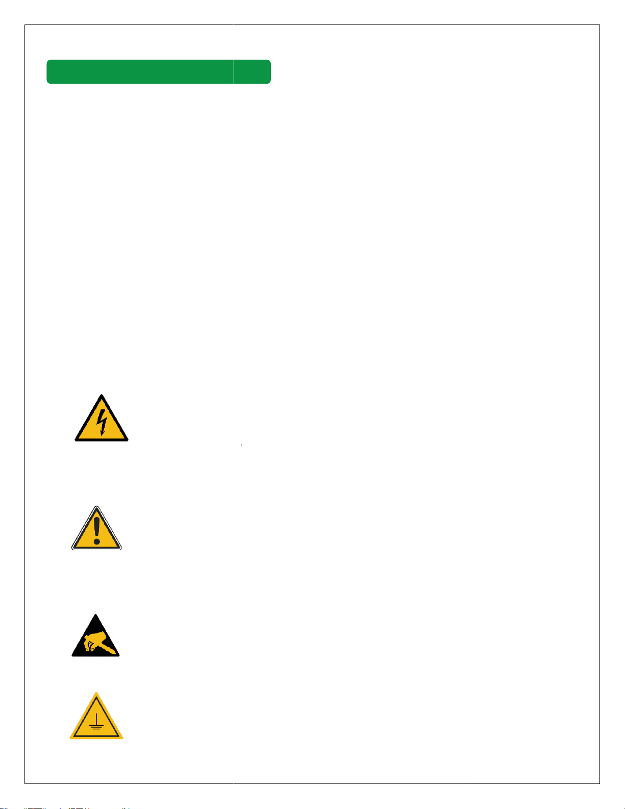
Representation of Safety Instructions
At various points in this document, you may notice notes and
hazards. The symbols used have the following meaning:
Danger
Some components of the charger carry hazardous voltage in operation. Direct or
indirect contact through moist objects with these components will result
Attention
Means that damage to property can occur if the corresponding safety measures are not
taken.
ESD
This symbol reminds you of the possible consequences of touching elect
Ground Protection
SAFETY MEASURES AND INSTRUCTIONS
Harmony series EV Charger complies with IEC 61851
-
1, Safety Standard. All the components used in the
charger are certified. The charger complied with all the norms as per the safety standard. For user safety,
g stations are equipped with a ground fault detector to reduce the risk of shock. Users are never
exposed to dangerous voltages or currents since connector pins are not energized until the connector is
inserted properly in the EV charging socket and commun
ication has been established between the vehicle
and the charging station. Besides, the connector is sealed to protect the live components from the
Representation of Safety Instructions
At various points in this document, you may notice notes and
precautionary warnings regarding possible
hazards. The symbols used have the following meaning:
Some components of the charger carry hazardous voltage in operation. Direct or
indirect contact through moist objects with these components will result
Means that damage to property can occur if the corresponding safety measures are not
This symbol reminds you of the possible consequences of touching elect
SAFETY MEASURES AND INSTRUCTIONS
1, Safety Standard. All the components used in the
charger are certified. The charger complied with all the norms as per the safety standard. For user safety,
g stations are equipped with a ground fault detector to reduce the risk of shock. Users are never
exposed to dangerous voltages or currents since connector pins are not energized until the connector is
ication has been established between the vehicle
and the charging station. Besides, the connector is sealed to protect the live components from the
precautionary warnings regarding possible
Some components of the charger carry hazardous voltage in operation. Direct or
indirect contact through moist objects with these components will result
in fatal injury.
Means that damage to property can occur if the corresponding safety measures are not
This symbol reminds you of the possible consequences of touching elect
rostatically
This symbol reminds you of that the equipment is properly grounded.