2 www.stryker.com
EN 7110-120-700 Rev-AB
Safety Directives
WARNINGS:
• Before using this equipment, or any
component compatible with this equipment,
read and understand the instructions for use.
Pay particular attention to safety information.
Become familiar with the equipment before
use.
• Only healthcare professionals trained and
experienced in the use of this medical device
should operate this equipment.
• The Stryker Universal Battery Charger
and Stryker F1 Universal Battery Charger
are limited to professional use within a
professional healthcare environment, excluding
near high frequency (HF) surgical equipment
and accessories. See the Electromagnetic
Compatibility section.
• Upon initial receipt and before each use,
operate the equipment and inspect each
component for damage. DO NOT use any
equipment if damage is apparent. See the
Inspection and Testing section for inspection
criteria.
• DO NOT use this equipment in areas in which
flammable anesthetics or flammable agents
are mixed with air, oxygen, or nitrous oxide.
• Take special precautions regarding
electromagnetic compatibility (EMC) when
using medical electrical equipment. Place this
equipment into service according to the EMC
information contained in this manual. Portable
and mobile radio frequency (RF) equipment
can affect the function of this equipment.
• ALWAYS use the appropriate battery charger to
charge battery packs.
• DO NOT operate the battery charger using a
voltage inconsistent with the rating on the back
of the unit.
• DO NOT operate the battery charger with a
damaged power cord or plug.
Introduction
This instructions for use manual contains
information intended to ensure the safe, effective,
and compliant use of your product. This manual is
intended for in-service trainers, physicians, nurses,
surgical technologists, and biomedical equipment
technicians. Keep and consult this reference
manual during the life of the product.
The following conventions are used in this manual:
• A WARNING highlights a safety-related issue.
ALWAYS comply with this information to
prevent patient and/or healthcare staff injury.
• A CAUTION highlights a product reliability
issue. ALWAYS comply with this information to
prevent product damage.
• A NOTE supplements and/or clarifies
procedural information.
For additional information, including safety
information, in-service training, or current literature,
contact your Stryker sales representative or call
Stryker customer service at 1-269-323-7700 or
1-800-253-3210. Outside the US, contact your
nearest Stryker subsidiary.
NOTE: The user and/or patient should report
any serious product-related incident to both the
manufacturer and the Competent Authority of the
European Member State where the user and/or
patient is established.
Trademarks not the property of Stryker
Corporation are the property of their respective
owners.
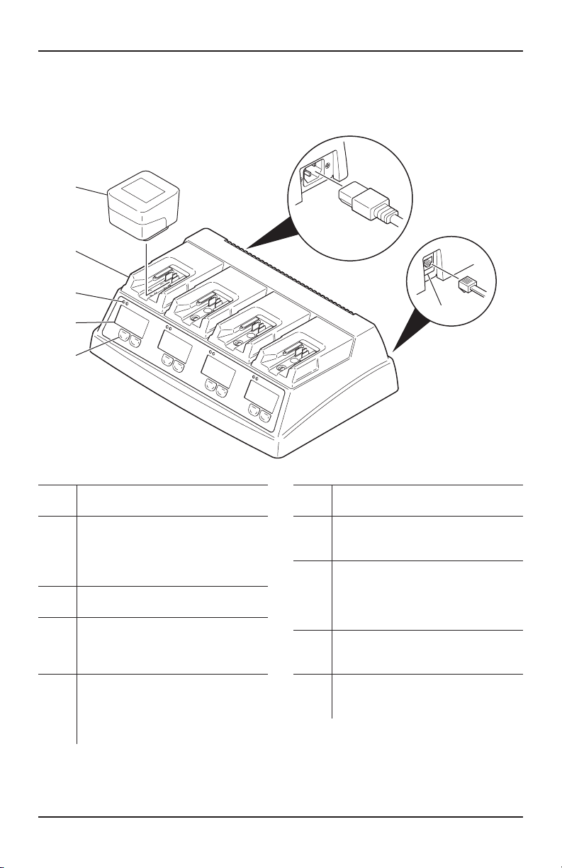
Indications For Use
The Stryker Universal Battery Charger and Stryker
F1 Universal Battery Charger (battery chargers)
are four-station, modular battery chargers intended
to charge Stryker handpiece battery packs only.
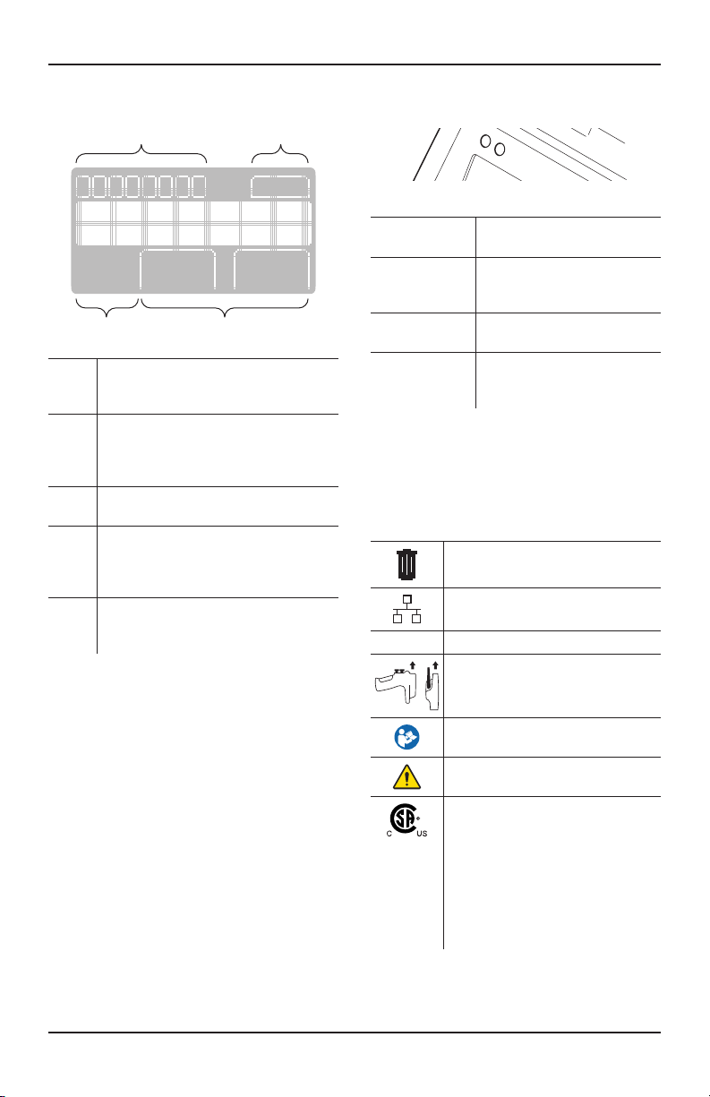
The battery chargers and battery packs are
specifically designed to work together so that the
battery charger’s information screen will provide
specific battery pack information.
Contraindications
None known.