EXICOM POWER SOLUTIONS Harmony Series User manual

Preface
This document is valid for the Harmony series EV Charger only.
The images used in this document are for illustration and instruction purposes only. The images and
descriptions in this document refer to a representative device design. The devices used by the user may
differ in their appearance and design.
We recommend that the charging station is always kept updated with the latest version of the software (as
per the latest release by the manufacturer), as this will ensure functional enhancements and product
improvements from time to time.
Purpose of this Guide
The document describes the troubleshooting of Harmony series EV Charger.
*Note: This document includes the latest information available at the time of printing. Exicom Tele-
Systems Ltd. reserves the right to make changes to this manual or product without further notice.
Changes, modifications, or repairs to this product by parties other than an authorized service provider
could void the product warranty.
Introduction to charger
Harmony – Fast charger solution is Exicom’s most innovative design till date and a true representation of
interoperability. The system has three connectors - CCS, CHAdeMO & AC TYPE 2: 142kW (DC: 120kW + AC:
22kW).
All guns can be used in Parallel for charging. The charger is equipped with multiple components as shown
below:
INTRODUCTION
Troubleshooting Guide - Harmony series EV Charger

[1] Housing The Cover [2] Key Operated Lock
[3] LEDs [4] LCD Display
[5] RFID Reader [6] Emergency Switch
[7] Cable Gland [8] Charging Cable
[9] Charging Gun Plug [10] SMR’s Cover
[11] Ventilation [12] Charging Gun Dummy Socket

Harmony series EV Charger complies with IEC 61851
components. IEC 61851-
1 Safety Standard is an International safety standard and Exicom Tele
the first Indian company
to comply with the same.
For the safety of the user, all charging stations are equipped with a ground fault detector to reduce the risk
of electric shock. The user is never exposed to dangerous voltages or currents because the connector pins
are not energi
zed until the connector is inserted properly in the EV charging socket and communication
has been established between the vehicle and the charging station. Besides, the connector is sealed to
protect the live components from the weather.
Representation of
Safety Instructions
Meanings of the symbols used in this document:
Danger
Direct or indirect contact through moist objects with these components can result in
fatal injury.
Attention
Damage to property can occur if the corresponding safety measures are
ESD
Electrostatically Sensitive Components
Ground Protection
Ensure that the equipment is grounded before use
SAFETY MEASURES AND INSTRUCTIONS
Harmony series EV Charger complies with IEC 61851
-
1 Safety Standard and uses only certified
1 Safety Standard is an International safety standard and Exicom Tele
to comply with the same.
For the safety of the user, all charging stations are equipped with a ground fault detector to reduce the risk
of electric shock. The user is never exposed to dangerous voltages or currents because the connector pins
zed until the connector is inserted properly in the EV charging socket and communication
has been established between the vehicle and the charging station. Besides, the connector is sealed to
protect the live components from the weather.
Safety Instructions
Meanings of the symbols used in this document:
Direct or indirect contact through moist objects with these components can result in
Damage to property can occur if the corresponding safety measures are
Electrostatically Sensitive Components
– Do Not Touch
Ground Protection
Ensure that the equipment is grounded before use
.
SAFETY MEASURES AND INSTRUCTIONS
1 Safety Standard and uses only certified
1 Safety Standard is an International safety standard and Exicom Tele
-Systems is
For the safety of the user, all charging stations are equipped with a ground fault detector to reduce the risk
of electric shock. The user is never exposed to dangerous voltages or currents because the connector pins
zed until the connector is inserted properly in the EV charging socket and communication
has been established between the vehicle and the charging station. Besides, the connector is sealed to
Direct or indirect contact through moist objects with these components can result in
Damage to property can occur if the corresponding safety measures are
not followed.

Prohibited Areas
Any unauthorized personnel should not open the cover. It can lead to risk of bodily harm and will result in
losing warranty qualification.
Safety Precautions
Make sure that the equipment is well-grounded to avoid electric shock before opening
the equipment.
Do not add to, modify or alter any part of this product without consulting the back-end
team.
Please make sure the input voltage, frequency and other conditions conform to
equipment requirements before the power on.
To ensure a proper service life of the equipment and its stable operation, do not use the
equipment in an environment that contains volatile gas or is flammable.
Dos & Don’ts for charger troubleshooting
Do not touch any live part in the system while troubleshooting when the system is ON.
Do not make any changes in the system without consulting the backend team.
Do not make any false commitment/give false explanations to the customer for any issue.
Understand the problem scenario before troubleshooting the issue.
Carry all required tools to site & spares for troubleshooting.
Required Tools
Multimeter, Clamp meter.
SD Card, U-Drive.
USB-RS232 serial tool, USB-UART serial tool
LAN Cable, IXXAT CAN Converter, LAPTOP.

The basic steps to approach the correct issue and resolve it are given below:
STEP 1 – Identify the issue
TROUBLESHOOTING APPROACH

STEP 2 – Check the issue
STEP 3 – Locate the issue

STEP 4 – Resolve the issue
Software:
Update Software
Use the latest Software
Faulty Parts:
Replace the faulty item
Use the correct MPN part
Other Faults:
Correct wiring,if loose
Take action as per the fault detail.

During charging, the vehicle requests for voltage & current and the charger delivers the same by
limiting the current as per requested current. However, charging may be stopped/interrupted by
various reasons. Charging can be stopped by the charger, the vehicle or by any other means. Charger
generates stop reason based on the nature of the cause of why the charging stops. The commonly
occurring stop reasons along with their explanations and resolutions are given below:
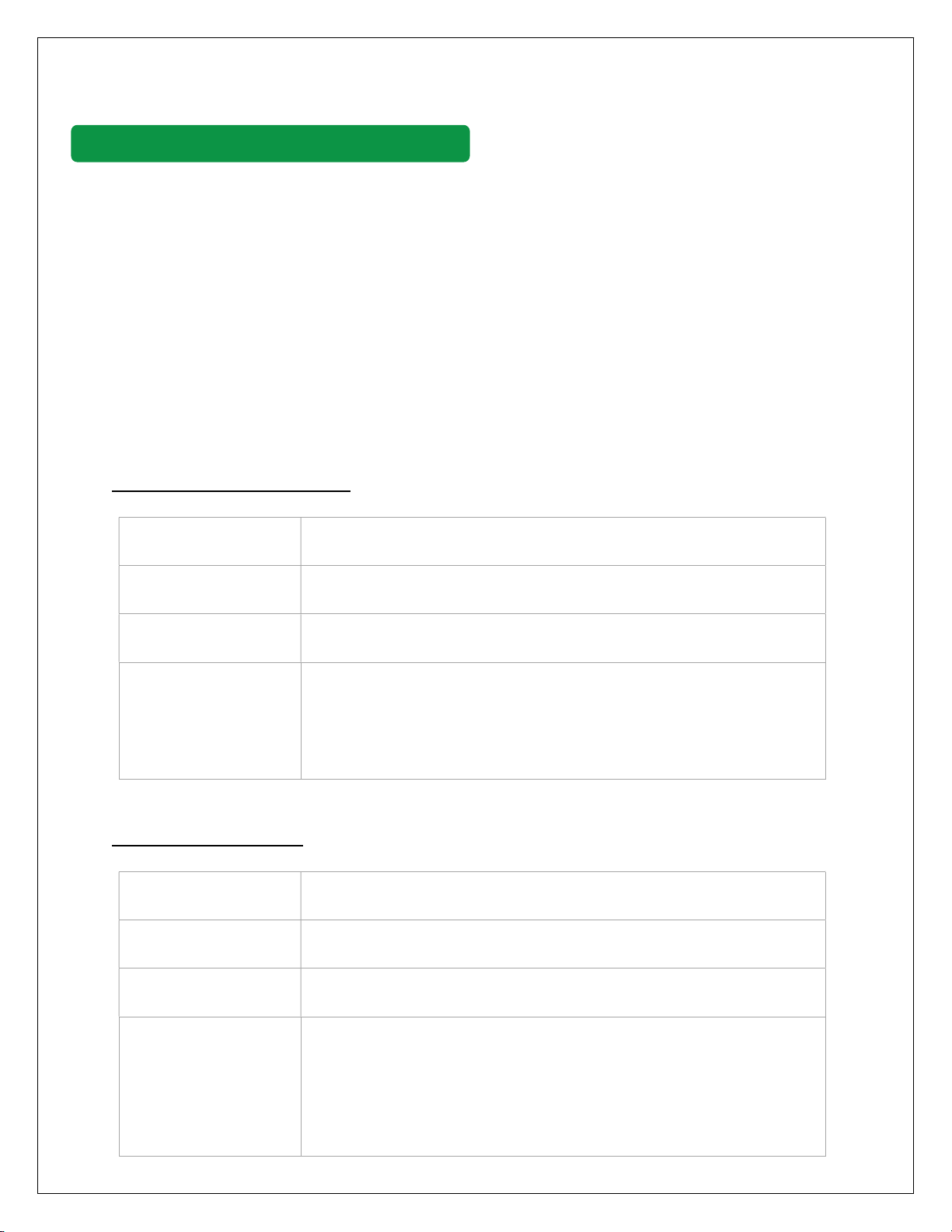
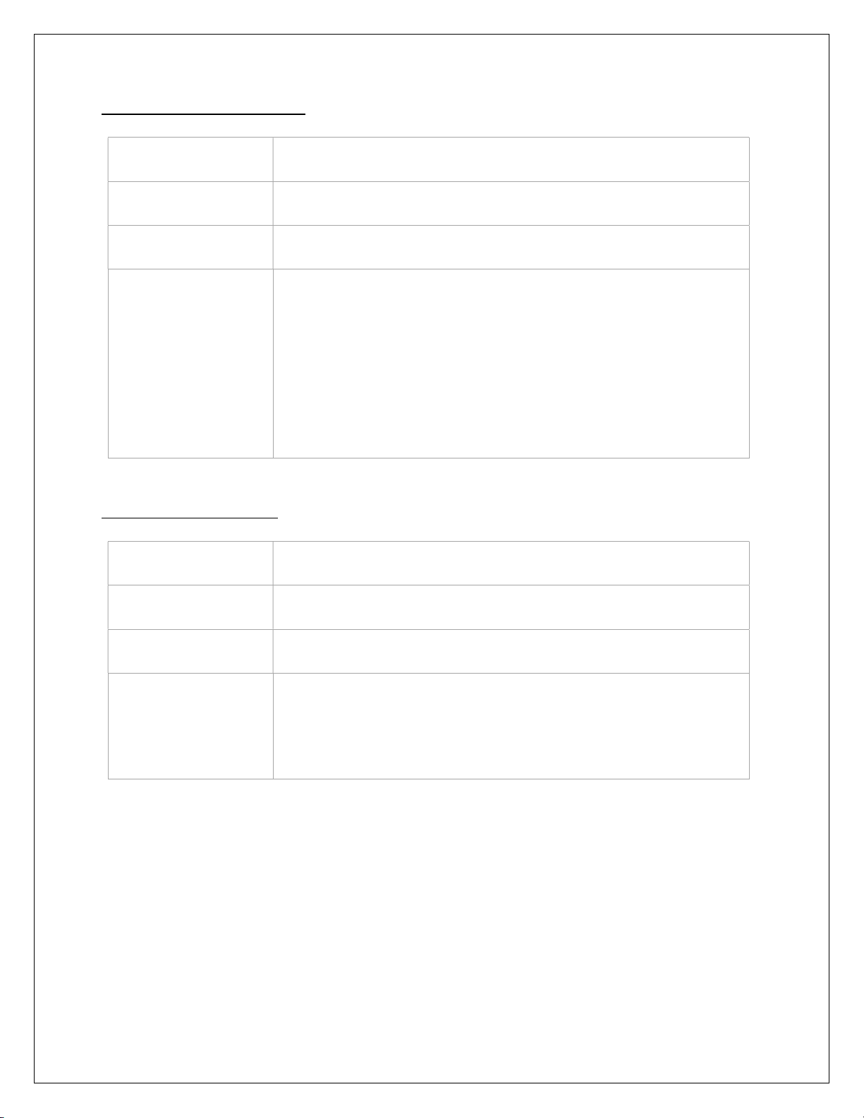
Charging Stopped/Interrupted by Charger
Parameter configuration failed
Error Code 201
Error Name Param config failed
Error Cause Related to charger PLC parameters configuration
Error Solution 1. Retry Charging.
2. If generated frequently take PLC serial and CAN log of the
respective gun and share for analysis.
Charging Enable timeout
Error Code 202
Error Name Charging enable timeout
Error Cause Start charging command is not received from the vehicle.
Error Solution 1. Retry Charging.
2. If generated frequently, please inform the vehicle
manufacturer regarding this.
3. If the issue persists, take PLC serial and CAN log of the
respective gun and share for analysis.
CHARGING STOP REASON TROUBLESHOOTING

Abnormal volt of outside bus
Error Code 203
Error Name Abnormal volt outside bus
Error Cause The pilot controller voltage measurement has deviation.
Error Solution 1. Check wires of 10-J30 connectors for the respective gun.
2. Check if rectifiers are building the voltage.
3. Please check if the backup battery voltage is within
range(330V-438V DC)
4. Check if DC contactors of the respective guns are working OK.
5. Re-calibrate the settings.
6. Take PLC serial and CAN log of the respective gun and share
for analysis.
Unable lock charging gun
Error Code 204
Error Name Unable lock gun
Error Cause Unable to lock the GUN.
Error Solution 1. Check the 12VDC output of Aux. the power supply.
2. Check if the pilot controller is sending a 12VDC signal to GUN.
3. Check if lock feedback sense wiring is OK.

Insulation inspection abnormally
Error Code 205
Error Name Insulation inspect abnormally
Error Cause Insulation test failed during charging initialization
Error Solution 1. Check if rectifiers are building the voltage.
2. Please check if the backup battery voltage is within
range(330V-438V DC)
3. Measure voltage at output.
4. Check voltage on the insulation board.
5. Change the vehicle and test again.
6. Take PLC serial and CAN log of the respective gun and
share for analysis.
Insulation inspection timeout
Error Code 206
Error Name Insulation inspect timeout
Error Cause Insulation test function timed out during charging initialization
Error Solution 1. Check if rectifiers are building the voltage.
2. Please check if the backup battery voltage is within
range(330V-438V DC)
3. Change the vehicle and test again.
4. Take PLC serial and CAN log of the respective gun and
share for analysis.

EV Relay pull-In timeout
Error Code 207
Error Name EV Relay pull-In timeout
Error Cause EV Contactors are not closed. This error only valid for CHAdeMO &
GBT.
Error Solution 1. Check battery voltage after contactors (The vehicle end). If
no voltage please inform the vehicle manufacturer.
2. Change the vehicle and test again.
3. Take CAN log of the respective gun and share for analysis.
Require Curr Timeout
Error Code 208
Error Name Require Curr Timeout
Error Cause Cannot receive CMD 101 signal or demand current is always 0. This
error is only valid for CHAdeMO.
Error Solution 1. Change the vehicle and test again.
2. Take CAN log of the respective gun and share for analysis
Remain time over stop
Error Code 209
Error Name Remain time over stop
Error Cause This is a Normal stop for CHAdeMO. The charging time greater
than the estimated time of the vehicle. Valid only for CHAdeMO
Error Solution 1. This is a normal stop, don’t panic.
2. If the vehicle SOC is not 100%, take CAN log of the
respective gun and share for analysis.

Ring fail alarm
Error Code 210
Error Name Ring fail alarm
Error Cause NA
Error Solution This is a reserved alarm. Shall not display on the charger, if
observed on-screen please coordinate with the R&D team.
Communication with EV failed
Error Code 211
Error Name Comm with EV failed
Error Cause This means communication failed with the vehicle. This may be
due to the vehicle or charger both.
Error Solution 1. Restart the vehicle and try charging again.
2. Change the vehicle and try charging again.
3. For CCS, CHAdeMO or GBT, take PLC serial and CAN log of
the respective gun and share for analysis.

Plugged gun timeout
Error Code 212
Error Name Plugged gun timeout
Error Cause This means the connector is not properly connected to EV or EV
changed CP voltage.
Error Solution 1. Check if the gun is properly connected to the vehicle.
2. Restart the vehicle and try charging again.
3. Check 12V between CP & PE on PLC board when gun not
connected, 9V when the gun is connected and 6V when
charging
4. Change the vehicle and try charging again.
5. Take PLC serial and CAN log of the respective gun and
share for analysis
Pre Charging fault
Error Code 213
Error Name Pre Charging fault
Error Cause Charging failed before start.
Error Solution 1. Check if rectifiers are building the voltage.
2. Please check if the backup battery voltage is within
range(330V-438V DC)
3. Measure voltage at output.
4. Check if the contactors are closing
5. Change the vehicle and test again.
6. Take PLC serial and CAN log of the respective gun and
share for analysis

Door open
Error Code 214
Error Name Door open
Error Cause The door is open or wiring loose.
Error Solution Close door/check wiring at the door sensor.
Emergency button pressed
Error Code 215
Error Name EPO
Error Cause Emergency button pressed or wiring loose.
Error Solution Release Emergency button / check wiring at button.
SPD fail
Error Code 216
Error Name SPD fail
Error Cause SPD failure or loose wiring.
Error Solution Change SPD if faulty(check red colour on SPD) / check wiring of
SPD.

All Rectifier fail
Error Code 217
Error Name AllRectFail
Error Cause All rectifiers have failed
Error Solution 1. Check SMR CAN wiring.
2. Check if all SMR are inserted properly.
3. Check if AC MCB/DC MCB is ON & AC/DC input voltage is
healthy.
4. Open the cover and check SMR red LED, if RED LED is ON,
remove each SMR and check individually.
Mains Fail
Error Code 218
Error Name Mains Fail
Error Cause All rectifiers have failed or AC input is not available.
Error Solution 1. Check SMR CAN wiring and check if all SMR are inserted
properly.
2. Check if input MCB is ON & input voltage is healthy.
AllRectCommFail
Error Code 219
Error Name AllRectFail
Error Cause All rectifier communication has failed
Error Solution 1. Check SMR CAN wiring.
2. Check if all SMR are inserted properly.
3. Check if AC MCB/DC MCB is ON & AC/DC input voltage is
healthy

E-Lock Failed
Error Code 220
Error Name E-Lock Failed
Error Cause Locking of Gun has failed.
Error Solution 1. This is only for the GBT connector.
2. Please check the connector e-lock configuration in display.
3. Check 12V pulse for LKA+ & LKA-.
4. Check gun lock feedback wires.
Gun Over temperature
Error Code 221
Error Name Gun Over-Temp
Error Cause Contact point at the vehicle inlet is high
Error Solution 1. Change the vehicle and try again.
2. Observe temperature with an external device.
Output short circuit
Error Code 222
Error Name Output short circuit
Error Cause DC+ & DC- is shorted at the output
Error Solution 1. It is reported from the power module.
2. Take a pilot controller to SMR CAN data on CAN port3. The
baud rate is 125Kbps

PWM failure
Error Code 223
Error Name PWM has failed for GUN-C
Error Cause PWM failed because of GUN-C.
Error Solution AC connector PWM connection failure. Please check the AC
connector cable.
Ground Fault Detected
Error Code 224
Error Name Ground Fault Detected
Error Cause Earth wire is disconnected
Error Solution The earth is not properly connected. Please check the system
wiring.
CR Comm Fail
Error Code 250
Error Name CR Comm Fail
Error Cause RFID reader has failed.
Error Solution 1. Please check if RFID is ON/OFF
2. Please check if RFID cable is connected

kWhMeter Comm Fail
Error Code 251
Error Name kWhMeter Comm Fail
Error Cause kWh meter communication has failed.
Error Solution 1. Check if DC energy meters are ON or OFF.
2. Please check the wiring of meters.
CCU Comm Fail
Error Code 252
Error Name CCU Comm Fail
Error Cause The pilot controller’s communication with the upper controller has
failed.
Error Solution 1. Check if the pilot controller is ON or OFF
2. Please check the RS485 wiring of the pilot controller with
an upper controller

Charging stopped/Interrupted by Vehicle
S.No
Alarm name Alarm code Alarm Cause Alarm Resolution
1 EV Request
Stop
2 Alarm is
reported by
Vehicle
1. Please change the vehicle and try again
charging.
2. Inform the user to check at the vehicle end.
3. Please take serial data & CAN1/CAN2 data of
PLC module. Also capture SMR data from
controller's CAN3 Port.
2. Battery
overvoltage
301 Alarm is
reported by
Vehicle
1. Please check the power module output
voltage to make sure it matches the EV
required voltage.
2. Please change the vehicle and try again
charging
3. Inform the user to check at the vehicle end.
4. Please take serial data & CAN1/CAN2 data of
PLC module. Also capture SMR data from
controller's CAN3 Port.ort.
3
Battery
under
voltage
302 Alarm is
reported by
Vehicle
1. Please check the power module output
voltage to make sure it matches the EV
required voltage.
2. Please take serial data & CAN1/CAN2 data of
PLC module. Also capture SMR data from
controller's CAN3 port.
4 Battery
current
deviation
error
303 Alarm is
reported by
Vehicle
1. Please check the power module output
current to make sure it matches the EV
required current.
2. Please take serial data & CAN1/CAN2 data of
PLC module. Also capture SMR data from
controller's CAN3 port
5 High battery
temperature
304 Alarm is
reported by
Vehicle
1. Please change the vehicle and try again
charging.
2. Inform the user to check at the vehicle end.
3. Please take serial data & CAN1/CAN2 data of
PLC module. Also capture SMR data from
controller's CAN3 Port.

6 Battery voltage
deviation error
305 Alarm is
reported by
Vehicle
1. Please change the vehicle and try again charging.
2. Inform the user to check at the vehicle end.
3. Please take serial data & CAN1/CAN2 data of PLC
module. Also capture SMR data from controller's
CAN3 Port.
7 Charger
Connector Lock
Fault
306 Alarm is
reported by
Vehicle
1. Please check the connector, inlet, or plug out and
in again.
2. Please change the vehicle and try again charging.
3. Inform the user to check at the vehicle end.
4. Please take serial data & CAN1/CAN2 data of PLC
module. Also capture SMR data from controller's
CAN3 Port.
8 Vehicle shift
position
307 Alarm is
reported by
Vehicle
1. Please change the vehicle and try again charging.
2. Inform the user to check at the vehicle end.
3. Please take serial data & CAN1/CAN2 data of PLC
module. Also capture SMR data from controller's
CAN3 Port.
9 Error Status
Noticed by EV
308 Alarm is
reported by
Vehicle
1. Please check the rectifier present current voltage.
2. Please change the vehicle and try again charging.
3. Inform the user to check at the vehicle end.
4. Please take serial data & CAN1/CAN2 data of PLC
module. Also capture SMR data from controller's
CAN3 Port.
10 PLC Low-Level
Comm Fail
309 Alarm is
reported by
Vehicle
1. Unable to set up communication.
2. Please change the vehicle and try again charging.
3. Inform the user to check at the vehicle end.
4. Please take serial data & CAN1/CAN2 data of PLC
module. Also capture SMR data from controller's
CAN3 Port.
Other manuals for Harmony Series
1
Table of contents
Other EXICOM POWER SOLUTIONS Batteries Charger manuals