Exide GNB ELEMENT Series Manual


TABLE OF CONTENTS
SAFETY PRECAUTIONS .......................................................................................................................... 1
CHARGER SPECIFICATIONS ................................................................................................................. 3
INSTALLATION PROCEDURE ................................................................................................................ 4
CHARGER ELECTRICAL INSTALLATION ........................................................................................... 7
CHARGER CONTROLS AND USER INTERFACE............................................................................. 10
OPERATING PROCEDURE .................................................................................................................... 12
CHARGER MENUS .................................................................................................................................. 15
TROUBLESHOOTING.............................................................................................................................. 20
APPENDIX.................................................................................................................................................. 26

Sales xService xRecycling 888.563.6300 in the USA 800.268.2698 in Canada 1
SAFETY PRECAUTIONS
BEFORE ATTEMPTING TO OPERATE THE CHARGER, PLEASE READ THIS GUIDE CAREFULLY.
SAVE THESE INSTRUCTIONS – This guide contains important instructions for ElementHigh
Frequency series product line that shall be followed during installation and maintenance of the charger.
Only qualified personnel should install, operate, or service this equipment.
WARNINGS:
¾WARNING Risk of High Voltages – Lethal voltages are present within the charger enclosure
whenever the ac line is energized and/or the battery/load is connected. The heatsinks and other
internal components present the risk of electric shock.
¾WARNING Risk of Improper Grounding – The charger must be connected to an ac power supply
incorporating an earth/ground. The grounding conductor must be of a size equal to or larger than
the line (phase) conductors.
¾WARNING Risk of Explosive Gases – Working in the vicinity of a lead-acid battery is dangerous.
Batteries generate explosive gases during charging and discharging. To reduce the risk of battery
explosion, follow these safety instructions as well as those published by the battery manufacturer.
¾WARNING Protect Eye and Skin – Wear safety goggles and skin protection while installing your
battery charger or working in the vicinity of lead-acid batteries.
¾To reduce the risk of injury, only charge rechargeable lead-acid batteries. Charging other battery
types may cause damage and result in personal injury.
CAUTIONS:
¾Risk of electric shock from stored energy.Wait at least two minutes after de-energizing the ac
line and disconnecting the battery/load before removing the cover.
¾Risk of electric shock and/or electric energy - high current levels. Do not touch un-insulated
battery, connectors or terminals. All tools should be adequately insulated to avoid the possibility of
shorting connections. Inspect cables often for damage to the insulation. Replace cracked or worn
cables immediately.
¾Risk of fire or explosion from gases vented by batteries.Be sure to discharge static electricity
from tools and technician by touching a grounded surface in the vicinity of the batteries. To prevent
damage to the connectors and reduce the risk of explosion due to arcing, connect or disconnect the
battery plug only when the charger output is off. ALWAYS press the STOP pushbutton before
unplugging the battery to prevent arcing.
¾Risk of electrical component failure due to improper connection. If the charger is incorrectly
wired to input or output devices, or wiring is not in accordance with local safety codes and
standards, the unit is at risk of being destroyed.

Sales xService xRecycling 888.563.6300 in the USA 800.268.2698 in Canada 2
¾Risk of electrical component failure due to improper installation.To prevent damage from
overheating, proper airflow must be ensured. Do not restrict fan inlets or exhaust outlets. Do not
mount the charger in a confined space or where the exhaust air will recirculate.
¾There are no user serviceable parts within the charger enclosure. If service is required, contact the
local GNB Industrial Power service representative.
¾The charger is NOT for outdoor use. Do not expose the charger to rain or snow.
¾Do not disconnect the battery while under charge.
IMPORTANT:
¾Follow the battery manufacturer's published instructions when installing, charging and servicing
batteries.
¾These instructions assume a certain level of competence by the installer and/or user. The following
practices and codes contain relevant information, and should be consulted for safe handling,
installation, testing, and maintaining deep cycle batteries. Applicable state and local codes must be
followed.
xNESC,National Electric Safety Code, ANSI C2-1993 (or latest revision). Copies may be
obtained by writing:
The Institute of Electrical and Electronics Engineers, Inc.
345 East 47th Street, New York, NY 10017, USA
xNEC National Electrical Code NFPA-70 (or latest version) available from: National Fire
Protection Association, Batterymarch Park, Quincy, MA 02269
xFederal Codes:
29CFR1926.441 "Safety Requirements for Special Equipment"
29CFR1910.151(c) "Medical Services and First Aid"
29CFR1910.305(j) "Wiring Methods, Components and Equipment"
STD 1-8.2(e) "OSHA Standing Directive"
xEMC Compliance:
This device complies with Part 15 section 103 of FCC Rules as a digital device used exclusively
as a power system in public utilities or industrial plants.
Operation is subject to the following two conditions:
(1) This device may not cause harmful interference, and
(2) This device must accept any interference received, including interference that may
cause undesired operation.

Sales xService xRecycling 888.563.6300 in the USA 800.268.2698 in Canada 3
CHARGER SPECIFICATIONS
The Element system specifications are listed below.
LMT-06kW-48-xxxS LMT-10kW-48-
xxxT
LMT-10kW-80-
xxxT
Nominal VA Ratings 48V / 150A 48V / 250A 80V / 120A
Input Specs.
Voltage 480VAC, 3-phase +10% Delta Connection with Earth
Ground
Current (nominal) 8.3A rms / phase 13.8A rms /
phase
13.8A rms /
phase
AC Circuit Size 15A 20A 20A
Power Factor 0.96 (Active Power Factor Correction)
Output Specs.
Voltage 48V Nom. /
62.5V Max.
48V Nom. /
62.5V Max.
80V Nom. /
110V Max.
Current 150A Max.
250A Max. 120A Max.
Power 6 kW Max. 10 kW Max. 10 kW Max.
Pk-Pk Voltage Ripple < 1%
Efficiency (typical) 92% at Full Load
Protection
Input ¾Under voltage
¾Over Voltage
Output ¾Over Current
¾Over Voltage
¾Over temperature
¾Battery reverse polarity protection
Operating Conditions
Ambient Temperature 0 – 40oC
Humidity 10-90% RH non-condensing
Interface
Communication Isolated RS-232 (Ethernet optional)
User Interface LCD/Keypad, RS-232, IR with a PDA (Palm Pilot)
Cooling Forced air (fans)
Mechanical
Dim. WxDxH 29"x8.5"x28"
Weight ~ 98 lb
Output Cabling 2/0 cables
Output Connectors SBX w/aux. contacts or Euro Connector
Auxiliary Contacts Interface with 5kȍbattery thermistor (optional)
Certifications UL and cUL Listed
Note: Design and/or specifications are subject to change without notice. If questions arise,
contact your local sales representative for clarification.
Sales xService xRecycling 888.563.6300 in the USA 800.268.2698 in Canada 4
INSTALLATION PROCEDURE
I. Charger Inspection
1. Upon receipt of the Element charger, verify that the shipping information (packing list)
matches the charger rating (label on the side of the charger).
2. Upon receipt of the Element charger, ensure that there is no physical damage to the
chassis, the LCD/keypad, the E-Stop/Disconnect switches, or the AC/DC cables. If you
notice any damage, inform the shipping carrier and/or GNB Industrial Power.
Do not install or operate the unit if it has received a sharp blow, been dropped or
otherwise damaged.
II. Charger Physical Installation
1. Ensure that the charging area is well ventilated, dry, and adequately clean.
2. Do not restrict airflow to the bottom air filter or top cover. Leave at least 1 ft spacing
between the sides of the charger and any adjacent walls or barriers and 2 ft spacing
between the bottom of the charger (air filter) and the floor / any mounting brackets.
3. Use a cardboard sheet as a template to mark the locations for the hardware on the wall.
4. Drill and install the hardware needed to mount the charger on the wall.
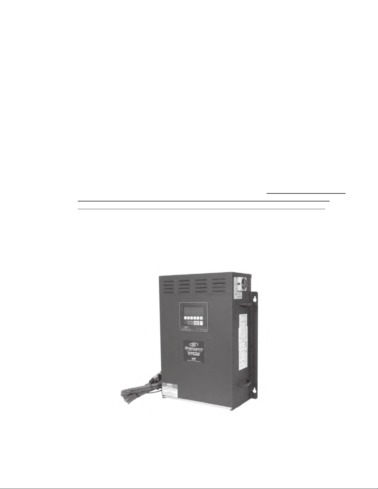
5. Lift the charger and mount it on the wall using the installed hardware (Figure 1).
Use ¼-20 hardware with lock washers to secure the charger to wall.
Figure 1: Charger installation

Sales xService xRecycling 888.563.6300 in the USA 800.268.2698 in Canada 5
CAUTION: When installing, do not lift the unit from the middle of the lower cover as this
may damage the filter. To reduce potential for filter damage, lift the charger using the
lifting handles mounted on either side of the charger chassis (see Figure 2).
Figure 2: Charger lifting instructions
III. Installing / Removing Air Filter
The charger is equipped with an air filter located in the lower cover of the unit. The air
filter needs to be checked on a regular basis and cleaned if needed.
ATTENTION: To clean the filter, use soap and water; dry thoroughly before
installing.
To remove the filter, hold the open end of the filter and slide out. To re-install, slide the
filter into the lower cover guide and push in until fully inserted (Figure 3).
Lifting
Handles

Sales xService xRecycling 888.563.6300 in the USA 800.268.2698 in Canada 6
Air filter
Filter Guides
Figure 3: Installing / Replacing Air Filter

Sales xService xRecycling 888.563.6300 in the USA 800.268.2698 in Canada 7
Charger Electrical Installation
1. Verify proper AC line voltage and current ratings per the charger specifications as listed on the
label on the side of the unit (see table below for proper AC line ratings).
AC Line Ratings for Element Chargers
Charger Model AC Voltage AC Current Disconnect Circuit
(@125%)
LMT-06kW-48V 480VAC 3(±10%) & GND 8.3 A nominal 15 A
LMT-10kW-48V-250A
LMT-10kW-80V-120A
480VAC 3(±10%) & GND
13.8 A
nominal 20 A
2. Verify that the main power and emergency stop switches on the unit are in the off (stop)
positions.
3. Figure 4) then push out one of the knockouts on the top cover to pass the AC conduit through.
The AC & GND wire connections are shown in
4. Figure 5.
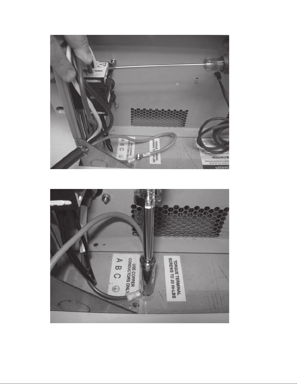
5. Connect the input 480VAC power cable to the three pole AC block terminals marked ABC
(Figure 6). Connect the GND wire to the terminal marked GND as shown in Figure 7.
6. Note that the unit is not phase rotation sensitive, but noted here to avoid confusion.
7. Verify the line and ground connections of the outlet or junction box (4-Wire Delta – No
Neutral).
CAUTION: Verify that input and output wiring adheres to all local safety codes and standards.
THE UNIT IS NOW READY FOR OPERATION.
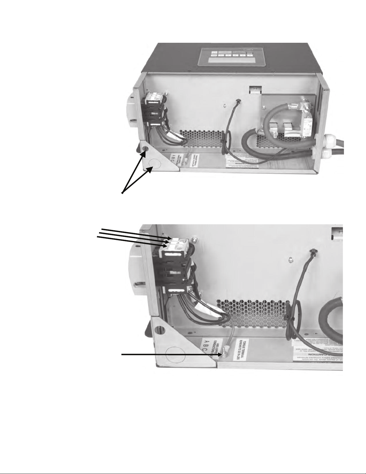
Figure 4: Removing top cover
Figure 5: AC wire connections
AC Knockouts
480VAC
3GND
Sales xService xRecycling 888.563.6300 in the USA 800.268.2698 in Canada 8
Sales xService xRecycling 888.563.6300 in the USA 800.268.2698 in Canada 9
Figure 6 : Making AC wire connections
Figure 7: Connecting GND wire

Sales xService xRecycling 888.563.6300 in the USA 800.268.2698 in Canada 10
Charger Controls and User Interface
The charger main disconnect is located on the upper right side of charger. The user interface panel is
located on the front of the charger (see Fig. 8).
Fig. 8: Charger Controls
The following is a brief description of the charger controls:
1. Main Disconnect Switch: This is a padlock type disconnect switch that should be in the OFF
position and padlocked before any panels or drawers are removed. It disconnects AC power
from all parts of the system.
2. LCD/Keypad Assembly: The main user interface for viewing and displaying operation and fault
messages as well as programming the charger.
¾The disconnect switch action is rotational where turning the switch clockwise will move the switch to
the ON position (arrow pointing up) while turning the switch counter clockwise will move the switch
to the OFF position (arrow pointing to the left) as shown in Fig. 9.
Fig. 9: Disconnect and Stop Switch Actions
1- Main
Disconnect
Power Switch
2-LCD /
Keypad
Sales xService xRecycling 888.563.6300 in the USA 800.268.2698 in Canada 11
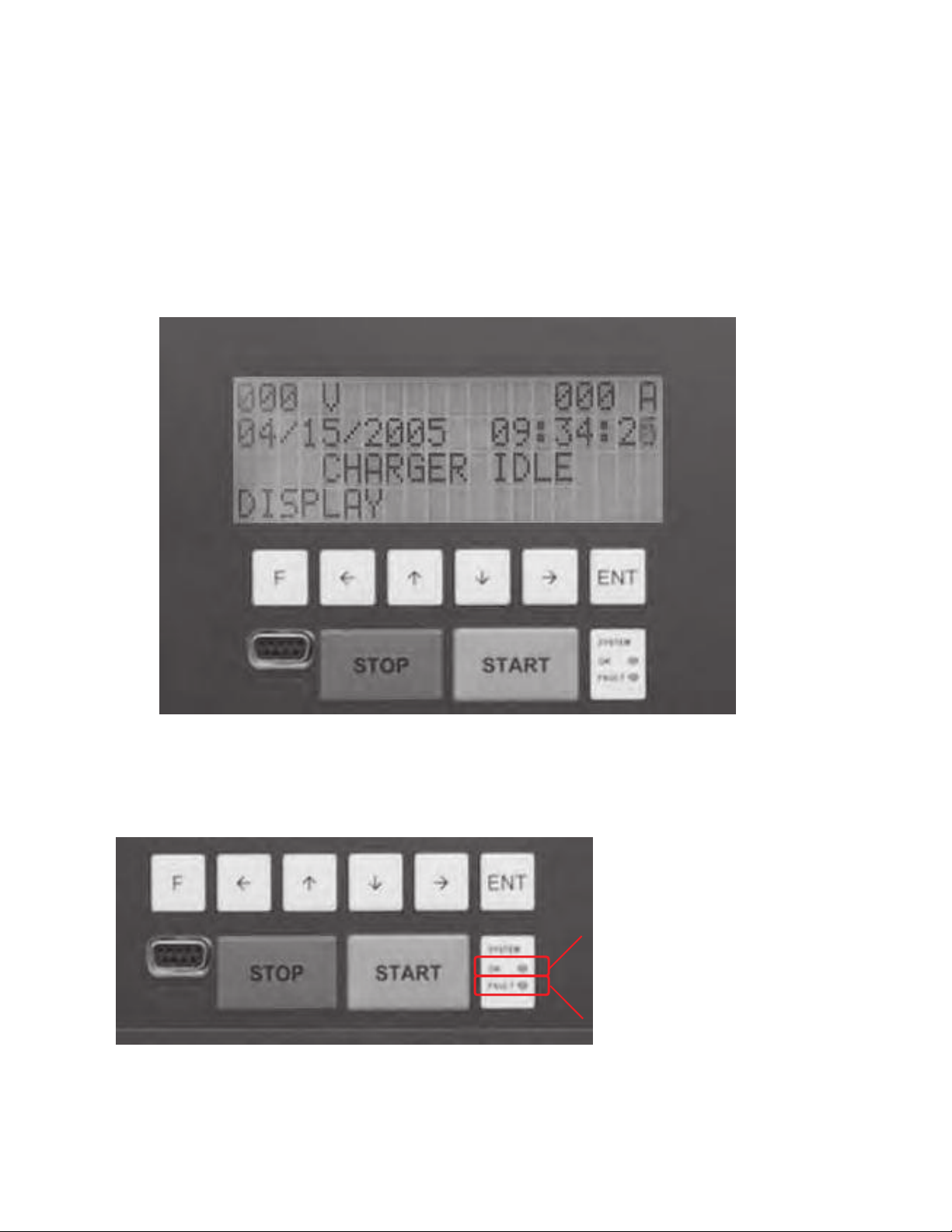
¾The LCD/Keypad assembly shown in Figure 10 encompasses:
oA4x20 character LCD for operation and fault message display
oA1x6 push button keypad with separate START and STOP push button
oTwo status LEDs for run (OK) and Fault indication
oAserial RS-232 connector and an IR window
Fig. 10: LCD/Keypad and User Interfaces
¾The status LEDs indicate the charger status, namely OK (Green LED lit) for normal operation, Fault
(Red LED lit) when a fault trips (Fig. 11). For faults and troubleshooting, refer to the
troubleshooting section of this manual.
Fig. 11: Charger status LEDs
OK LED
FAULT LED
LCD
RS-232
IR
Status
LEDs
Sales xService xRecycling 888.563.6300 in the USA 800.268.2698 in Canada 12
OPERATING PROCEDURE
I. Turning on the Unit
1. Connect charger to truck’s battery using DC connectors.
2. Energize the AC Mains.
3. Energize the side panel AC input main disconnect switch (RED). Verify that the LCD display
is lit and displays the “Connect Battery” screen shown below.
4 8 V 2 0 0 A
0 7 / 1 9 / 0 7 1 2 : 0 0 : 0 0
C O N N E C T B A T T E R Y
D I S P L A Y
If the LCD is not lit, if the above message is not displayed, or the fans are not operating,
perform the following:
A. Turn off the unit (de-energize the disconnect switch)
B. Ensure proper AC wiring
C. Ensure the main AC disconnect (wall) is energized
D. Verify fuses in main AC junction box (wall)
E. If wiring and fan operation check OK proper and the problem persists, contact GNB
Industrial Power.
Note: The LCD will display the battery voltage and the maximum current settings on the first line,
namely 48V and 250A for a 10kW ELEMENT charging system.
Battery Voltage Setting Charger Maximum Current
Sales xService xRecycling 888.563.6300 in the USA 800.268.2698 in Canada 13
II. Starting a Charge Cycle
1. Connect the truck’s battery to the charger. Once the battery is detected, the LCD message
will change to “Push Start to Begin Cycle”.
4 8 V 2 0 0 A
0 7 / 1 9 / 0 7 1 2 : 0 0 : 0 0
P U S H S T A R T T O
B E G I N C Y C L E
If the above message is not displayed, the battery may not have been detected. Make sure
that the battery cables are connected properly and verify that the auxiliary contacts are
proper and making good contact. Once a battery is connected, the above message will be
displayed.
2. To start the charger, press the START button. A STARTING CHARGE screen will appear
for few seconds as shown below.
S T A R T I N G C H A R G E
E X I T
3. The charge cycle will start and the following screen showing the charging operation will be
displayed.
M M C H A R G E H H : M M : S S
V : X X X . X A : X X X X
T : X X X F A H : X X X X
E F 5 2 %
“MM” indicates the active charging mode, which can be Trickle, CC, CV, Finish, or Equalize.
The Charge Timer, Battery Voltage, Current, Temperature, and returned Amp-Hours will all
be displayed. Also, the battery state of charge is shown at the bottom of the screen.
4. To stop the charge cycle, press the STOP button. A CHARGE CYCLE STOPPED screen
will appear as shown below.

Sales xService xRecycling 888.563.6300 in the USA 800.268.2698 in Canada 14
C H A R G E C Y C L E S T O P P E D
B Y U S E R
Pressing the STOP button for the second time will stop the charger completely and the unit
will default to the Charger Idle screen. If necessary, it is now safe to disconnect the charger
from the battery. Pressing the START button from the CHARGE CYCLE STOPPED screen
will resume the charge cycle and the screen will again display the Charger Operation
screen.
5. Once the charge cycle has completed, the following screen will be displayed.
C Y C L E H H : M M : S S
C O M P L E T E
T E M P : X X X F A H R S : X X X X
E X I T
The elapsed charging time, the battery temperature in degrees F, and the total retuned
amp-hours will be displayed.
It is now safe to disconnect the battery from the charger.

Sales xService xRecycling 888.563.6300 in the USA 800.268.2698 in Canada 15
CHARGER MENUS
Users can access various menus of the charger to view charge history, charger lifetime operational
history, charger settings, charger model and serial number as well as activate a recovery cycle for a
sulfated battery.
The charger menus can be accessed when the charger is idle, i.e. when the “Connect Battery”or the
“Push Start to Begin Cycle”screens are displayed. Pushing the function key “F”will display the
charger “Main Menu”while pushing the up/down (q/r)keys allows scrolling between the various menus
of the charger.
I. Charge Cycle History
1. With the “Connect Battery”or the “Push Start to Begin Cycle”screens are displayed,
push the function key “F”. The “Charge History”menu will first appear.
M A I N M E N U :
C H A R G E H I S T O R Y
E X I T E N T E R
Pressing the “EXIT”key will exit the charger menus while pressing the “ENTER”key will access
the selected menu.
2. Push the ENTER key to access the charge cycle history. The charger can hold up to 100
charge cycles which can be displayed (Note that the first cycle will be cycle 0 and the last
will be cycle 99). The last charge cycle is displayed first. Note that the charger will only
save the last 100 charge cycles.
C H # 9 9 0 7 / 1 9 / 0 7 0 4 : 2 0
V O L T : 5 8 . 6 H R S : 0 3 : 2 1
TEMP:98F AHRS:562
The above screen will display the following:
CH#XX: Charge cycle number
01/01/05: Start date of the charge cycle
04:20: Start time of charge cycle
VOLT: Battery end of charge voltage
HRS: Duration of charge cycle
TEMP: Maximum battery temperature recorded
AHRS: Amp-hours returned

Sales xService xRecycling 888.563.6300 in the USA 800.268.2698 in Canada 16
3. Pressing the left/right (/)keys will display the second screen of the charger history.
C H # 9 9 0 7 / 1 9 / 0 7 0 4 : 2 0
ACTIVATED PROFILES:
T R C C C V F I E Q
STATE:XXXXXXXXXXXXXX
The second screen lists additional relevant information about the charge cycle including:
ACTIVATED
PROFILES: Lists the profiles that were activated during that cycle.
STATE: Shows whether the cycle completed successfully or interrupted by the user
or due to a fault.
The ACTIVATED PROFILES allows users to check whether certain profiles were activated
during certain times (e.g. equalize cycles on the preset days). The STATE field lists the state of
the charge when the cycle was terminated. The following messages may appear:
COMPLETED: Cycle completed successfully
STOPPED: Cycle stopped by user
XX FAULT # Y: Charger fault with drawer # Y
If a fault took place, the reference to the drawer number allows quick identification of a problem
or faulty drawer.
4. Pressing the up/down (q/r)keys allows scrolling between the various charge cycles saved.
II. ACTIVE PROFILES
While in the Main Menu,press the up/down (q/r)keys until the Charge Profiles screen appears.
A C T I V E P R O F I L E : P 0
P 0 : T R C C C V Z P
P 1 : T R C C C V F I E Q Z P
The Active Profile screen shows the charger’s active profile as well as the profiles 0 and 1
settings. For each profile, the programmed charge modes are listed. Refer to the charger
programming section for further details.

Sales xService xRecycling 888.563.6300 in the USA 800.268.2698 in Canada 17
III. Charger Lifetime History
While in the Main Menu,press the up/down (q/r)keys until the Lifetime Summary screen
appears.
M A I N M E N U :
LIFETIME SUMMARY
E X I T E N T E R
Pressing the “ENTER”key will access the selected menu. The charger lifetime operational
summary screen will then appear.
FIRST CHARG:07/19/07
C H R G H O U R S : 1 2 3 4
A M P H O U R S : 1 2 3 4 5
K W H O U R S : 1 2 3 4
The above variables allow users to verify charger usage since installation and compare usage of
aspecific charger versus others in the vicinity or in the plant.
IV. CHARGER MODEL AND SERIAL NUMBER
While in the Main Menu,press the up/down (q/r)keys until the Charger Model screen appears.
MODEL:PCHG-LV-60048
M F G I D : 2 0 0 5 0 1 0 0 0 1
M F G D A T E : 0 7 / 1 9 / 2 0 0 7
R E V I S I O N : 1 . 1 0
The charger model number, ID, manufacturing date and firmware revision are shown for
reference.
V. RECOVERY CYCLE FOR SULFATED BATTERIES
One of the unique features of this charger is the ability to activate a long safe recovery cycle for
sulfated batteries. This can be easily done by accessing the recovery cycle screen and starting a
recovery cycle for a given battery.
1. While in the Main Menu,press the up/down (q/r)keys until the Recovery Cycle for
Sulfated Battery screen appears.
This manual suits for next models
3
Table of contents
Popular Batteries Charger manuals by other brands

Fullwat
Fullwat FU-CLI1000 quick start guide

IntelliPeak
IntelliPeak Ice instruction manual

EMPORIA
EMPORIA Smart Home EV Charger Installation & Usage Guide

Clarke
Clarke IBC80 Operation & maintenance instructions

Schumacher
Schumacher SP-400 owner's manual

Sony
Sony Rechargeable Battery Pack operating instructions


