EXPANSION ELECTRONIC ECOKITCHEN 1 User manual

USE AND INSTRUCTION MANUAL
File 20190402-001
ELECTROSTATIC PURIFIER
MODEL
ECOKITCHEN
TYPE
1-2-3

3
CONTENTS
1. ECOKITCHEN ELECTROSTATIC PURIFIER ........................................................................................ 4
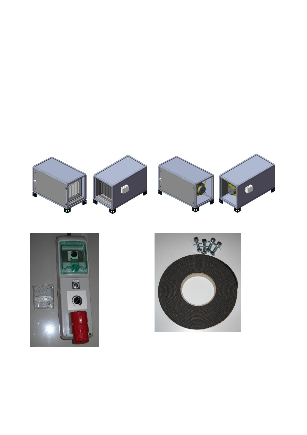
MACHINE COMPONENTS.............................................................................................................................................. 4
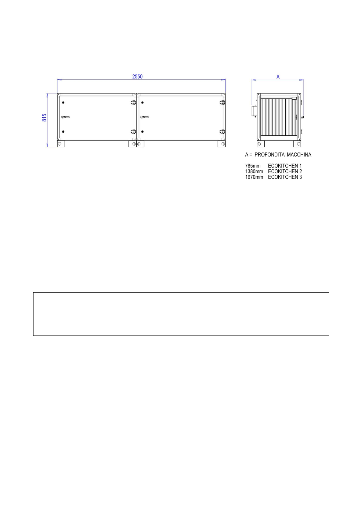
2. OVERALL DIMENSIONS.............................................................................................................................5
3. TRANSPORTATION AND PACKAGING ..................................................................................................5
4. FIELD OF APPLICATION............................................................................................................................6
5. MACHINE INSTALLATION........................................................................................................................ 7
7. DISPOSAL ..................................................................................................................................................... 11
8. WORKING PARAMETERS........................................................................................................................ 12
8.1 TABLE OF FLOW-EFFICIENCY OF THE MACHINE................................................................................. 12
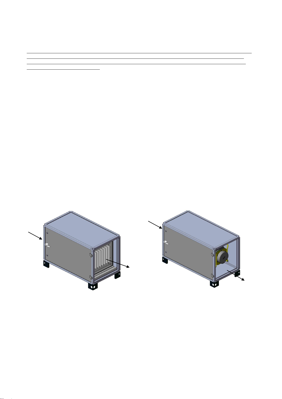
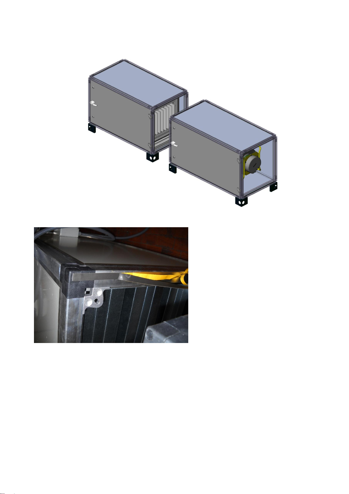
9. ECOKITCHEN COMPONENTS ................................................................................................................ 12
10. FILTER MAINTENANCE........................................................................................................................... 16
11. GENERAL CONTROL OF THE ELECTROSTATIC CELL AND PRE-FILTER............................... 18
12. CONTROLS ON THE ELECTROSTATIC FILTER................................................................................ 19
12.1 CLEANING THE IONISATION WIRES........................................................................................................ 19
12.2. REPLACING ELECTROSTATIC CELL IONISATION WIRES................................................................... 19
13. ELECTRIC PANEL...................................................................................................................................... 20
2. ADJUSTMENTS POTENTIOMETER....................................................................................................... 21
3. TECHNICAL INFORMATION................................................................................................................... 23
16.1. TECHNICAL CHARACTERISTICS OF PURIFIER ..................................................................................... 23
16.2. CHARACTERISTICS OF ELECTRIC FAN................................................................................................... 23
16.3. ECOKITCHEN 1INSTALLED FILTERS...................................................................................................... 23
16.4. ECOKITCHEN 2INSTALLED FILTERS...................................................................................................... 24
16.5. ECOKITCHEN 3INSTALLED FILTERS...................................................................................................... 24
4. SPARE PARTS .............................................................................................................................................. 24

4
1. ECOKITCHEN ELECTROSTATIC PURIFIER
The ECOKITCHEN cleaner, as it is supplied, cannot be used directly, but must be completed by all the other
elements that allow air collection and channelling.
The machine provides the electrostatic filter section and the deodorising activated carbon section for
purification and the electric fan for air intake. All other elements (channels, hoods, cabins, etc.) must be
provided on site by the user.
MACHINE COMPONENTS
The machine is composed of:
A - Structure containing the filters and the DEOX system
B - Structure containing the activated carbons and the fan
C - electric panel
D - screws and gasket kit
E - filtered air outlet
A - front and rear views
B - front and rear views
C - view of electric panel with brackets for wall
mounting
D - screws and gasket kit for coupling
For the commissioning, the two sections of Filtration+DEOX and Carbons+Fan must be joined together by
the special screw kit so as to form a single structure. The two sections are then joined together by the
special multipolar connector.

2. OVERALL DIMENSIONS
3. TRANSPORTATION AND PACKAGING
The machine is normally packed with a number of layers of bubble wrap and stretch film. Normally it does
not require a pallet as it is already equipped with feet that lift it from the ground and make it easy to move
with forklifts equipped with through-brackets.
For handling:
- protect the structure against any scratches and accidental blows
- do not place loads on top of it
- do not turn upside down
- do not expose to the elements.
All accessories are inserted inside the fan compartment. During transportation, the
external structure and control panel of the machine must not be damaged, so verify
immediately at the time of delivery that there is no visible damage. Sign the delivery
receipt conditional to verification. Use suitable lifting systems to unload or load machine
from means of transport and for installation.

6
4. FIELD OF APPLICATION
The machine can be used for:
- extracting fumes through a hood placed above the fumes emission point and connected to the machine by
means of a channel of suitable dimensions
- positioning the machine in a place that does not block normal work operations
- positioning in a point that does not cause danger during the handling of goods with transport and lifting
equipment (forklifts, bridge cranes ...)
- filtration of fumes that the machine is suitable for
- intake of fumes with a maximum temperature of 50 °C
Intake of air polluted by fumes must be done by means of a section of pipe of appropriate size. The pipe
must not oppose a higher resistance than the pressure characteristics of installed electric fan.
Maintaining high filtration performance depends on:
- intakes of pollutants alone, that the purifier is suitable for
- regular maintenance of the filters as described in the attached filters manual
POLLUTANTS THAT CAN BE FILTERED BY THE FILTERING SYSTEM
The purifier can be used in the presence of pollutants having the following characteristics:
dry fumes
low oil content fumes
very fine powders (up to 0.3 microns)
electrically chargeable fumes
The machine was built for the most common pollutants such as:
food cooking fumes and vapours from hoods with filters and labyrinths
fumes from welding ferrous materials
fumes from welding non-ferrous materials (aluminium, bronze, brass, etc..)
fumes from welding precious materials (gold, silver, etc..)
POLLUTANTS THAT CANNOT BE FILTERED
The purifier is not suitable for filtering substances with the following characteristics:
- water mists
- high quantities of powders
- shavings, iron filing powders and residues in general
- gas
The electrostatic filter must absolutely avoid all following substances:
- metal powders, even very fine ones
- combustion fumes from organic and inorganic materials (wood, coal, naphtha, diesel, petrol, etc..)
- explosive environments

7
5. MACHINE INSTALLATION
The place where the machine will be placed is under the sole responsibility of those who install and use this
equipment. It is therefore necessary to remember that the machine must not endanger people who pass
through or work nearby. All risks arising from normal work procedures as well as from extraordinary ones
that may occur, must be assessed.
The purifier should preferably be installed in a sheltered place, on feet or supports (not supplied) on the floor
or on walls or ceilings using non supplied suitable support systems.
It is also recommended to respect the following points:
do not turn the machine on its side
if the machine cannot be placed on the floor, create a raised supporting surface for the purifier
if the machine is placed outdoors it is necessary to set up a canopy and walls that protect it from
rain, the electrical panel must always be placed in a dry place.
Any elements needed for installation (supports, canopies, etc.) are not included in the supply and those
using this machine must set them up at the site.
For installation, proceed as follows:
position the machine in the established place
connect pipes or accessories required for fumes intake
connect electrical panel to electrical supply network
adjust any shutters on the air intake pipe
5.1 MECHANICAL CONNECTION
Verify that the installation space can contain the equipment and that there is enough space for safe
installation.
Identify the inlet and outlet of the different sections.
IN
OUT
IN
OUT
Filtering section
Ventilation section

8
The 2 sections that make up the unit must be positioned on the same plane to connect them together.
Bring the units close together, with the outlet of the filtering section in front of the inlet of the ventilation
section
Apply the supplied adhesive gasket all along the entire perimeter of the filtering section

9
Join the 2 sections with the relative screws, using the relative self-centring blocks. Close with a 6mm Allen
key.
The two joined sections will form a single body and will then be electrically connected together by the special
electrical connector.

10
6. ELECTRIC PANEL INSTALLATION
The electrical panel is supplied with brackets for wall mounting and it is connected and wired up to the first
junction box by a flexible sheath with a standard length of 3m.
Mount the special brackets on the panel and fix it to the wall with suitable plugs.
Deliver the supply voltage by the supplied socket, observing the neutral and earth connections.
The phase sequence in three-phase systems does not matter since the fan is electronic and can never turn
in the opposite direction.
6.1 ELECTRICAL CONNECTION
To power the machine, it is necessary to provide the power supply using the special plug supplied with the
electrical panel.
The connection must be set up by an electrician. The earthing system shall be provided by the user.
The electrical supply network for the panel must meet the following conditions:
For machines with single-phase power supply, recognisable by a 3-pin BLUE plug
Voltage : 230V +/- 10% Volt
Frequency : 50/60 Hz
Minimum available power : 1.5 kW
For machines with three-phase + neutral power supply, recognisable by a 5-pole RED plug
Voltage : 400V +/- 10% Volt between phases + neutral line
Frequency : 50/60 Hz
Minimum available power : 3.5 kW
6.2 DISASSEMBLY
Proceed as follows:
- disconnect the electrical panel from the electrical supply network
- disconnect the pipes or accessories set up for fumes intake
- disconnect the sections of the machine
- remove the machine

11
7. DISPOSAL
For scrapping the machine, proceed according to provisions of law in force in the user's country. In
demolition phases (disassembly, transport, etc.) observe the safety provisions in the user manual.
Divide the various components of the machine by type of material, grouping them by:
- electrical and electronic components
- electric cables
- plastic materials (sheaths, sound-absorbent material, rubber ....)
- ferrous materials
- aluminium
- ceramic
- materials to be sent to authorised waste disposal companies (used filters)
The product or parts of it placed on the market after August 13, 2005, with this symbol (WEEE)
on the package, in the manual or on another part, is subject to Directive 2003/96/EC and to Lgs.
D. 151/2005.
This product cannot be disposed of as urban waste, but must be assigned to separate waste
collection. Any violation is penalised according to the current regulations.
Inquire about the methods established by local authorities for separate collection of electrical
and electronic products. The product can also be delivered to a dealer of a similar device at the
time of a new purchase and who cannot refuse the trade-in.
Incorrect disposal of the product, or improper use of said product or parts thereof is harmful to
the environment and human health. Correct disposal of products bearing the WEEE symbol helps
avoid any consequence for the environment and human health.

12
8. WORKING PARAMETERS
8.1 TABLE OF FLOW-EFFICIENCY OF THE MACHINE
The purifier is suitable to operate at different air flows adjustable by means of the special potentiometer,
equipped with 2 trimmers for adjusting the minimum and maximum points that it can work within.
Increasing the air flow above the set maximum point leads to a reduction in filtration efficiency. The
maximum air flow is adjusted with an anemometer with connected intake-exhaust system.
8.2 FLOW-PRESSURE CHARACTERISTICS
ECOKITCHEN systems are designed to provide an available head of 600Pa for intake and exhaust pipes at
maximum air flow rate. The table shows the flow and head values of the electric fan (pressure is intended as
available for pipes).
Model
Maximum air flow rate [m3/h]
Useful pressure for pipes
with clean filters
[Pa]
ECO1
2500
500
ECO2
4250
500
ECO3
6500
800
9. ECOKITCHEN COMPONENTS
A B C D E F G
H I
A- Metal/sponge pre-filter
B- XFE standard electrostatic filter
C- XFE electrostatic filter (2nd stage optional)
D- Droplet/turbulator separator
E- XFI negative ion emitter module
F- XFX Ozone generator module
G- Turbulator
H- Granular activated carbon filters
I- Radial electronic electric fan

13
9.1 METAL+SPONGE PRE-FILTER
This filter is made of a stratified pressed aluminium mesh
filter, combined with a high quality sponge and a galvanised
sheet frame.
The frame consists of 2 shells that can be opened and re-
used to wash the filter components.
The sponge air filters are made in standard dimensions ac-
cording to EN standards compliant with ASHRAE standards
to fit perfectly inside the air treatment unit. The most suit-
able application fields for these kinds of filters are in sectors
with high quantities of oils and greases, such as particular
types of industrial applications and in commercial kitchen
units.
9.2 FEL ELECTROSTATIC FILTER
FEL filters are particularly suitable for the abatement of pol-
lutants such as oil mists and vapours with and without par-
ticulate, produced during cooking phases.
The main special feature of this filter is observed in the
lower part of the collector blades, where the specially-
designed shape allows high
amounts of oily pollutant to drip, with the reduced formation
of electric discharges between the plates. In addition, the
special mechanical construction guarantees that no electri-
cal discharges occur on the insulators, even in the presence
of water vapour, ensuring high reliability over time.
The open lower part allows what is condensed during filtra-
tion to collect on specially prepared tanks. The high separa-
tion capacity along with a high particulate retention capac-
ity, achieves compact abatement systems with
low pressure losses, almost constant over time and with
high efficiency.

14
9.3 FI IONISATION SECTION
The new FI negative ionisation cell has been designed and built to be
applied inside air handling units or along air distribution channels.
FI represents a brand new development in the air handling field and its
insertion after electrostatic or absolute high efficiency filtering, guaran-
tees a reduction of odours and sterilisation of the walls, along with
greater environmental comfort.
Thanks to its multipolar connection system, it is possible to insert multi-
ple ionising cells according to the filtration and air flow requirements;
they are assembled and disassembled by simply sliding on guides in
the air handling centre. The
integrated electronic power supply circuit is equipped with LEDs, which
signal correct filter operation.
Model
air flow m3/h
Emission of ions/cm3 @ 100mm
XFI300
700 to1600
5'000’000
XFI600
1300 to 6800
5'000’000
9.4 FX OZONISATION SECTION
FX ozonising cell is ideal for deodorisation, sanitisation, hygienisation
and disinfection of air in plants and environments as it is able to de-
grade and eliminate any polluting or harmful elements such as viruses,
bacteria, mites, spores, moulds, insects and even harmful chemicals
and unpleasant odours. Thanks to its multipolar connection system, it is
possible to insert multiple ozonising cells according to the filtration and
air flow requirements; they are
assembled and disassembled by simply sliding on guides in the air
handling centre. The integrated electronic power supply circuit is
equipped with LEDs, which signal correct filter operation.
Model
air flow m3/h
Emission Range O3 [ppm] or [µg/m3]
XFI300
400 to 1700
Min. 0.1ppm or 196µg/m3MAX.
XFI600
800 to 3400
5'000’000
9.5 DROPLET SEPARATOR OR TURBULATOR SECTION
Droplets separators or turbulators are made of stainless steel, always
of the same base dimensions as the electrostatic filters. Their function
is to retain any oil droplets that could leak out of the filters if used at
high flow rates or to create a turbulence between Ions and Ozone if
combined with the FI and FX modules, to promote deodorisation before
the activated carbons.

15
9.6 LABYRINTH ACTIVE CARBONS SECTION
The active carbons section shows a series of flat filters ar-
ranged in a labyrinth to create an air passage on a larger
surface compared to a classic panel and at a lower speed.
A longer contact time between air and activated carbons is
obtained in this way, subsequently increasing the odour ad-
sorption effect and reducing pressure drops.
In addition, positioning the activated carbon battery after the
filters and the FI-FX modules extends their service life. The
panels can be opened to replace the activated carbon only,
thereby containing costs.
Diagram of air stream through the activated carbons

16
10. FILTER MAINTENANCE
Maintenance differs by method and time of intervention depending on the type of filter:
a) replacing the filter fibre in fabric pre-filters
b) washing pre-filters and the electrostatic cell
c) maintenance of the FI Ionisation and FX Ozonisation sections
d) replacing the activated carbon
e) washing the droplets separator or turbulator
These operations are very important and must be carried out with great care to always keep your equipment
active over time.
10.1 WASHING THE METAL + SPONGE PRE-FILTER
open the galvanised sheet frame
remove the sponge and metal pre-filter
components
Wash the separated parts with a degreasing
detergent in hot water
Squeeze the sponge and let the metal pre-
filter and frame drip
Put the components back in the frame
close the frame
put the filters back in
If the sponge or metal pre-filter are worn, replacement is recommended
10.1 WASHING THE PRE-FILTER AND ELECTROSTATIC FILTER
To perform correct maintenance, as the first operation, extract the pre-
filter incorporated in the electrostatic cell by lifting it for about one
centimetre and extract it as shown in the figure. For cleaning, prepare:
1) a plastic or stainless steel tank with decanting bottom
2) detergent (we recommend the one supplied by the manufacturer of
the machine).
3) protective gloves and glasses
4) suitable clothing.
5) running water.
Set up a stainless steel frame that keeps the filters raised from the base
of the tank to obtain a sludge settling bottom. Prepare the tank with
warm
(maximum 45 °C) or cold water depending on the type of detergent
being used. Add the diluted detergent according to proportions shown on
the label of the can and proceed:
a) immerse the electrostatic cell in the tank
b) allow it to soak for the amount of time indicated in the instructions for
use of the detergent or until the total all of the dirt has dissolved from the
cell

17
c) extract the filter, let it drip over the tank,
rinse it generously with running water, being
careful not to break the ionisation wires.
d) let it dry keeping it raised off the floor with
wooden strips or in a dryer with a maximum
temperature of 60 °C.
e) ensure that filter is clean and dry, then
insert it in its housing according to the
methods indicated on the sticker on the door.
N.B. Some alkaline-based detergents can
leave residues on the surface of blades
and insulators, that cannot be removed
through simple rinsing, and which lead to
voltage losses and therefore the
efficiency of the electrostatic cell even in
the presence of environmental humidity
of 50%. A solution is to immerse the cell
in an acidulated bath for a few minutes
and then rinse it again.
Wash the pre-filters in the same way, taking care not to damage them by bending or damaging the filter
mesh. If maintenance is not carried out according to provisions herein, the company will not be held
responsible for any faults, malfunctions or increase the frequency of maintenance.
10.2. MAINTENANCE OF FI NEGATIVE IONISATION CELL
The FI ionisation cell does not require frequent maintenance.
Every 6 months the emitting needles must be checked and kept clean
and every 12 months they need to be replaced.
To clean the needles it is recommended to use a cotton swab dipped in
multi-purpose degreasing detergent. If there are oxide deposits on the
surface of the needle, it is possible to use, instead of the cotton swab, a
Scotch-Brite abrasive sponge, also soaked in detergent.
To proceed with maintenance, it is advisable to cut off the power supply
to the FI cell, remove the cell from the central unit or air distribution
channel and clean each single needle.
To replace the needles, extract the cell from the central unit or from the
air distribution channel and,
holding the support, remove the worn needles and then put in the new
needles.
Normally, no other maintenance is required on this component. If the
ceramic insulators that separate the frame from the structure show
evident deposits of dirt, the entire FI cell can be washed in the same way
as the filters indicated in the previous paragraph.
EMITTING NEEDLE

18
10.3. FX OZONISATION CELL MAINTENANCE
The FX ozonisation module does not require
frequent maintenance.
Every 2-4 months the emitter wires must be checked
and kept clean and every 12 months they must be
replaced.
To clean the wires it is recommended to use a
cotton swab dipped in multi-purpose degreasing
detergent. In case of oxide deposits on the surface
of the wire, it is possible to use, instead of the cotton
swab, a Scotch-Brite abrasive sponge, also soaked
in detergent.
To proceed with maintenance, it is advisable to cut
off the power to the FX module, remove the module
from the central unit or from the air distribution
channel and clean each single wire.
To replace the wires, extract the module from the
central unit or from the air distribution channel and,
holding the support, remove the worn wires and then
put in the new ones.
Normally, no other maintenance is required on this
component. If the ceramic insulators that separate
the frame from the structure show evident deposits
of dirt, it is possible to proceed to with washing as
with the electrostatic filters.
DISPOSAL OF WASHING LIQUID
The liquid must not be dispersed in the environment and must be disposed of as washing waste and must be
taken to a suitable treatment plant.
11. GENERAL CONTROL OF THE ELECTROSTATIC CELL AND PRE-
FILTER
It is necessary to check the good state of the filters with every maintenance job. The following checks must
be carried out in the electrostatic cell.
CONTROL
ANOMALY
INTERVENTION
ionisation wires
broken wire
ionisation wire replacement
ionisation wires
rough oxidised surface or with
deposit of materials
clean the wire with a cloth soaked in
alcohol or a synthetic abrasive pad
ceramic insulators
dirty with deposit of materials
wash the electrostatic cell again
* ceramic insulators
breakage or presence of cracks
replace the insulator
* high voltage base
burns caused by high voltage
replace high voltage base
* For these interventions it is necessary to contact our local dealer.
During maintenance it is necessary to check that the metal pre-filter is not damaged or bent. In this case it
is necessary to replace the pre-filter

19
12. CONTROLS ON THE ELECTROSTATIC FILTER
Perform periodic checks to verify the status of its basic components, proceed to replace them in case of
breakage or perform preventive maintenance. Do the following:
- clean the ionisation wires
- replace the ionisation wires of the electrostatic cell.
12.1 CLEANING THE IONISATION WIRES
Some types of pollutants cause slight encrustation or oxidation of ionisation wires.
To avoid this it is necessary:
- to clean the wires with a cloth soaked in alcohol.
- to remove the oxide layer deposited on the wire with a very fine-grained synthetic abrasive pad (SCOTCH-
BRITE).
Do so every time there is a rough layer of oxide or deposits on the surface of the wire.
12.2. REPLACING ELECTROSTATIC CELL IONISATION WIRES
Ionisation wires are subject to wear due to the high voltage they are subjected to.
To avoid unexpected breakage, it is a good rule to replace all ionisation wires once a year, proceeding as
follows:
a) if an ionisation wire breaks, remove all pieces of wire present in the cell and remove the springs that keep
the wire taut
b) hook the spring to the eyelet of the wire as shown in the drawing
Ionisation wire Wire eyelet Closed ring
c) take the ionisation wire with curved nose pliers
as shown in the figure below
d) hook the end of the spring with the eyelet open
to the wire-tensioning rod of the electrostatic cell
e) keeping the ionisation wire taut with the other
hand, fasten it to the other wire-tensioning rod using
the curved nose pliers
Open ring

20
13. ELECTRIC PANEL
Connect the power supply to the electrical panel as explained
in the chapter on electrical panel installation.
START-UP
1) Open the door and turn the main switch from 0 (zero) to 1
(one).
2) The signal lamp must light up with GREEN light to indicate
correct operation of all systems.
3) Turn the potentiometer to adjust the intake speed according to
the operating requirements.
STOP
1) Open the door and turn the main switch from 1 (one) to 0
(zero).
2) The signal lamp turns off.
14. PROBLEMS ON THE MACHINE
TYPE OF FAILURE
CAUSE
INTERVENTION
No supply voltage
Check that the socket is powered by the required
supply voltage
General switch in position 0
(zero)
Turn the switch to the ON position (1)
Filter access doors of the open
machine
Close the filter access door with the special
closures
MACHINE DOES NOT
START
Machine door microswitch not
pressed or broken
Check that the microswitch press pin is intact and
press the limit switch correctly
Verify that the limit switch is working
Verify that the cables are connected and intact
Tripped thermal magnetic
circuit breaker due to a short
circuit
Remove the short circuit (contact assistance).
Machine door microswitch not
pressed or broken
Check that the microswitch press pin is intact and
press the limit switch correctly
Verify that the limit switch is working
Verify that the cables are connected and intact
SIGNAL LAMP OFF
Blown fuse
Replace the fuse with another of the same value
and type. If it blows again remove the electrostatic
filters and the ionisation and ozonisation sections
from the unit to check if one of these components
is short-circuited Contact technical assistance.
This manual suits for next models
2
Table of contents