Expert Sleepers CVM-8 User manual

CVM-8
Firmware v1.0
User Manual
Page 1

Copyright © 2022 Expert Sleepers Ltd. All rights reserved.
This manual as well as the hardware and software described in it is furnished under licence and
may be used or copied only in accordance with the terms of such licence. The content of this
manual is furnished for informational use only is subject to change without notice and should not
be construed as a commitment by Expert Sleepers Ltd. Expert Sleepers Ltd assumes no
responsibility or liability for any errors or inaccuracies that may appear in this document.
Page 2

Table of Contents
Introduction........................................................4
What is it?..........................................................4
Installation.........................................................4
Power requirements.......................................4
Inputs.................................................................4
LEDs..................................................................5
Startup...........................................................5
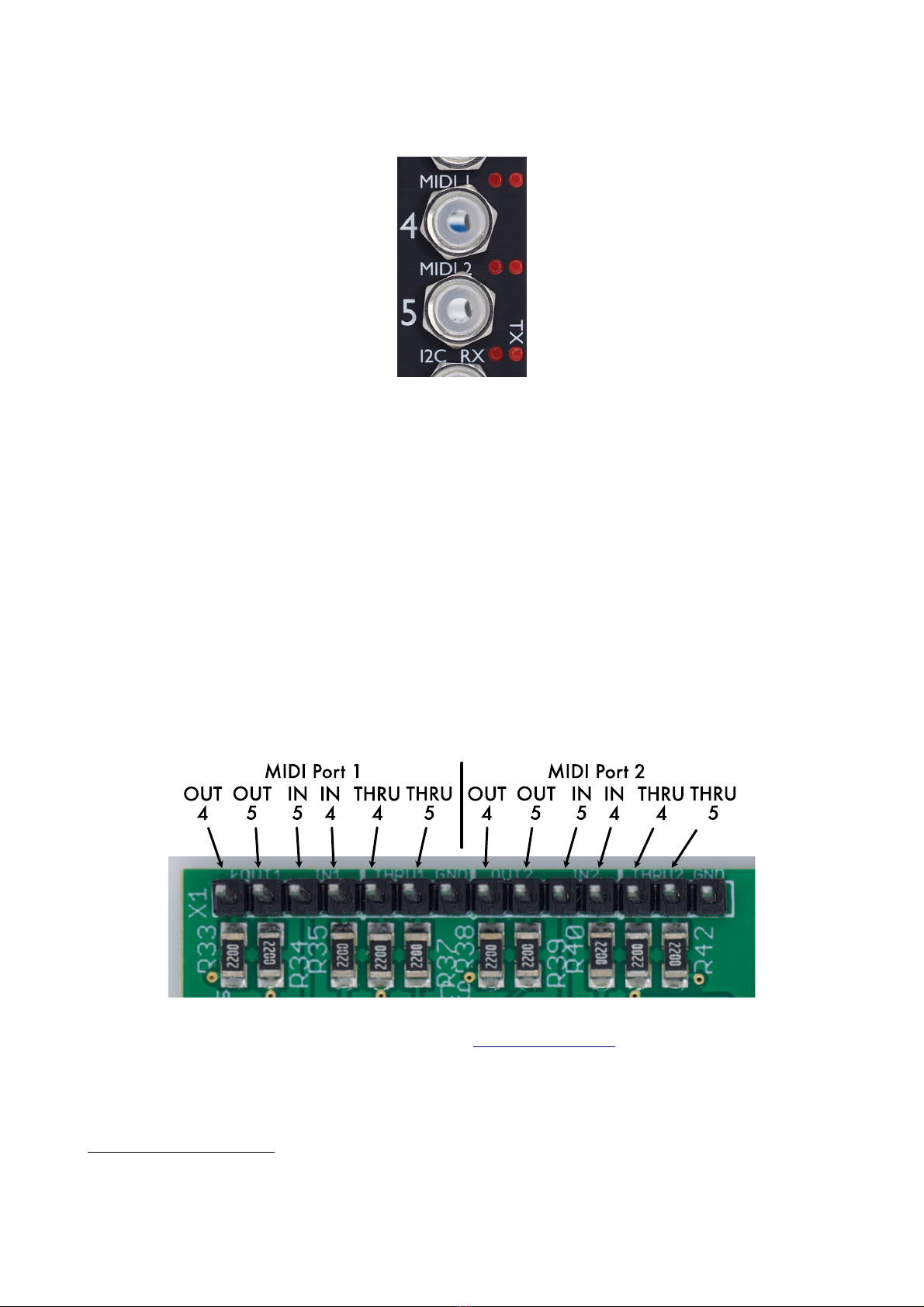
MIDI Connections.............................................5
I2C Connection..................................................6
Select Bus..........................................................6
DIP Switches......................................................7
Configuration Tool............................................7
Tool Setup.....................................................7
Raw Inputs....................................................8
Statistics........................................................8
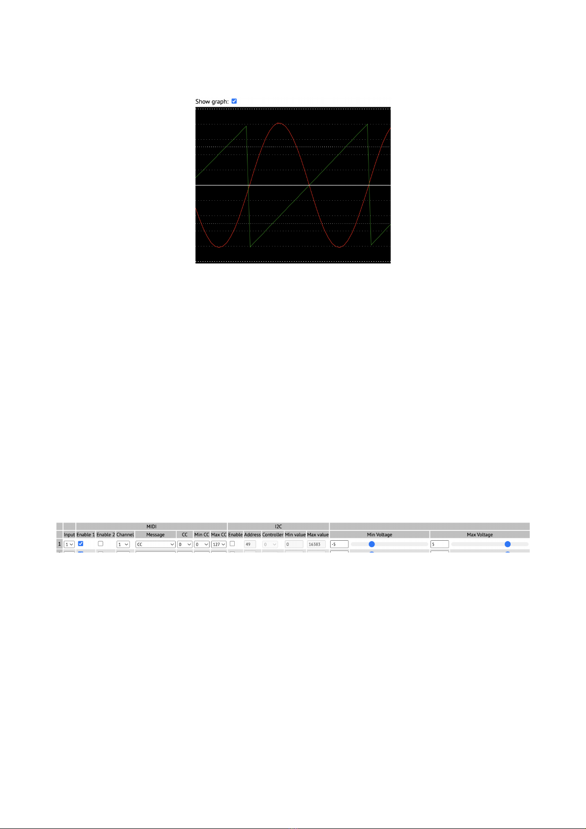
Graph View...................................................9
Configuration Wizard....................................9
Continuous Generators..................................9
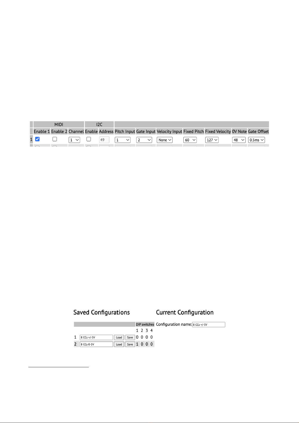
Note Generators..........................................10
Saving and loading configurations..............10
Settings........................................................11
Factory loaded configurations.........................12
MIDI System Exclusive (SysEx).....................13
SysEx Header..............................................13
Received SysEx messages...........................13
08H – Reboot..........................................13
22H – Request version string.................13
23H – Request raw inputs......................13
24H – Request configuration..................13
25H – Request statistics.........................14
26H – Request configuration names......14
27H – Request DIP switches..................14
28H – Request settings...........................14
30H – Update CC generator...................14
31H – Update configuration name.........14
32H – Update note generator..................14
33H – Update settings............................14
34H – Reset............................................14
40H – Reset configuration......................15
41H – Load configuration......................15
42H – Save configuration.......................15
Sent SysEx messages..................................15
10H – Configuration dump.....................15
11H – Configuration names...................15
12H – Settings........................................15
32H – Message.......................................15
33H – Raw inputs...................................15
34H – Statistics.......................................16
I2C Messages...................................................16
Sent I2C messages.......................................16
set i2c controller X to value Y................16
set voice pitch for note id.......................16
note on for specified note id...................16
note off for specified note id..................16
Received I2C messages...............................16
get raw ADC code (16 bit).....................16
get input voltage (16384 <-> 10V).........16
send message on MIDI port 1.................16
send message on MIDI port 2.................16
Firmware Updates............................................17
Where to get help.............................................17
Page 3

Introduction
Congratulations on your purchase of an Expert Sleepers CVM-8. Please read this user manual
before operating your new module.
What is it?
The CVM-8 digitizes control voltages on its inputs and uses them to generate MIDI or I2C
messages which can then be used to control other devices or software. For example you could
control a parameter on a hardware or software synth with a voltage (via a MIDI CC) or you could
convert analogue CV/gate into MIDI notes in order to play a synthesizer from a Eurorack
sequencer.
When used over I2C it can also work in a more passive mode where the I2C leader queries the
CVM-8 for its input voltages.
The CVM-8 has two completely independent sets of MIDI ports (a set being an input an output
and a 'thru' connection) and one header for I2C connection. One of the MIDI outputs can also
optionally drive the Select Bus.
Since the module has no user interface of its own it makes most sense to describe it in terms of the
functionality offered by the configuration tool documented below. Please read on.
Installation
House the module in a Eurorack case of your choosing. The power connector is Doepfer standard1.
If using the power cable supplied with the module the red edge of the cable is closest to the bottom
edge of the PCB and carries -12V. ("-12V" is marked on the PCB itself next to this end of the
connector.) Be sure to connect the other end of the power cable correctly again so -12V
corresponds to the red stripe on the cable.
Power requirements
The CVM-8 draws up to 66mA on the +12V rail and 25mA on the -12V rail.
It does not use the 5V rail.
Inputs
The CVM-8 has eight analogue inputs on 3.5mm TS jack sockets. The maximum voltage range that
can be handled is ±10.24V.
The jack sockets are illuminated lighting red for positive voltage and blue for negative voltage.
(Audio appears purple since it is a rapid alternation of positive and negative.)
1 http://www.doepfer.de/a100_man/a100t_e.htm
Page 4

LEDs
There are six LEDs on the CVM-8's panel. Refer to the image below:
The three pairs refer to the three channels of communication – MIDI 1 MIDI 2 and I2C. For each
pair the left LED indicates that the module is receiving and the right LED that the module is
transmitting.
Startup
When powered on the module's LED flash in patterns as follows.
Firstly the bootloader flashes the LEDs in the sequence MIDI 1 RX MIDI 1 TX MIDI 2 RX
MIDI 2 TX I2C RX I2C TX.
Then the module's firmware flashes the LEDs in the sequence MIDI 1 RX MIDI 2 RX I2C RX
I2C TX MIDI 2 TX MIDI 1 TX.
MIDI Connections
The CVM-8 has two independent MIDI ports each consisting of the traditional in out and thru.
They are exposed on the header strip across the top of the PCB marked X1.
Pin numbers refer to the 5-pin DIN socket as in the MIDI specification2.
All the necessary electronics are part of the module – all that is required to use these as MIDI ports
is the sockets either 5-pin DIN or TRS 3.5mm jack. Or they can be connected directly to the MIDI
headers on other Expert Sleepers or compatible modules. In this case remember to connect the
inputs to outputs and vice versa.
2 https://www.midi.org/specifications/item/midi-din-electrical-specification
Page 5

The header is a standard 0.1" pitch header compatible with e.g. typical IDC cable sockets or
DuPoint cables such as those supplied with the module.
The thru connections output a buffered version of the respective input without any intermediary
microcontroller i.e. they do not add any latency.
I2C Connection
The CVM-8 supports an I2C3 connection via the header on the PCB marked 'X2'. The GND SCL
& SDA lines are clearly marked on the PCB. Be sure to connect these to the corresponding lines on
the other I2C device(s) in use.
Make or remove I2C connections with the power off.
An I2C bus requires that somewhere on the bus are a pair of “pull up” resistors. The CVM-8
provides these on a switch labelled 'SW2':
The pull up resistors are enabled if the switch is towards the “PULL-UP” text (as shown in the
photo above) and disabled in the other position.
Select Bus
The Select Bus is a means of inter-module communication currently supported by a handful of
modules from various manufacturers including the Malekko Varigate 8+4 Macro Machines Storage
Strip5 and the Make Noise Tempi6 & René 27. Expert Sleepers modules which use the Select Bus
include the disting mk4 and disting EX.
The CVM-8 can only transmit on the Select Bus; it cannot receive. (So it is a leader only in the
parlance of some Select Bus devices.)
There is not an independent MIDI port to drive the Select Bus – it is driven by the output of MIDI
port 2. The Select Bus (if connected) and MIDI 2 will always output the same messages.
To drive the Select Bus the jumper (labelled 'X5' on the PCB) needs to be set appropriately. The
photo below shows the jumper in its factory fitted location on the rightmost pair of pins which
disables the Select Bus. To enable the Select Bus move the jumper to the left pair of pins (below
3 https://en.wikipedia.org/wiki/I²C
4 https://malekkoheavyindustry.com/product/varigate-8/
5 http://macromachines.net/products/storage-strip/
6 http://www.makenoisemusic.com/modules/tempi
7 http://makenoisemusic.com/modules/rene
Page 6

the words 'SELECT BUS' on the PCB).
When changing the jumper position please do so with the module powered off.
DIP Switches
The module has a set of four switches on the PCB marked 'SW1'.
These are used to choose the configuration to load at power on. Please see the section on saving and
loading configurations below.
If all four switches are set to the 'on' position this forces the module to start in bootloader mode
(see the section on firmware updates below). Usually this is not required as the configuration tool
can reboot the module into bootloader mode but if the module is not cooperating this provides a
means of forcing the issue.
Confi uration Tool
A GUI tool is provided to configure the CVM-8. Please find the version appropriate to your
firmware version on the firmware download page8.
A standalone version is provided for macOS and Windows as well as a platform-independent
browser-based version. This last uses the Web MIDI API which at the time of writing will work
only in browsers based on Google's Chromium (which includes Chrome).
All is well if the tool shows Web MIDI status: OK
If it shows Web MIDI status: No MIDI support in your browser then you need to use a different browser.
In general changes made in the tool are reflected immediately in the hardware. However nothing is
saved automatically – remember to save the configuration to flash memory if you want to keep it.
Tool Setup
The tool needs a MIDI connection to the CVM-8. Either MIDI port 1 or 2 can be used. You need to
connect both a MIDI in and a MIDI out.
At the top of the tool are these controls:
Use the drop-down menus to select the MIDI ports on your computer that you've connected to the
module.
8 https://expert-sleepers.co.uk/cvm8firmwareupdates.html
Page 7

To the right of the MIDI port menus are these buttons:
The 'Request Firmware Version' button sends and receives short SysEx messages to report the
CVM-8's firmware version.
'Query DIP Switches' asks the module to report the position of its DIP switches.
'Resynchronise' attempts to re-establish communication with the module and refresh the tool's view
of the module's state. You might use this for example if the module has been turn off and back on.
'Enter bootloader mode' is used to update the firmware – see below.
Below the buttons are three text boxes.
The left box is a log of messages reported by the tool. The centre box shows the last SysEx message
sent by the tool. The right box shows the last SysEx message received by the tool and in the case of
the 'Message' SysEx message the actual message as plain text.
Raw Inputs
Below the log messages is the raw inputs area.
Untick the check box if you don't want this area visible.
Three values are shown for each input. The top row shows the raw ADC code coming from the
hardware. The centre row shows the input as a voltage. The bottom row shows the processed ADC
codes that are used to generate MIDI and I2C messages which have been stabilised to avoid
excessive messages due to noise. A green value shows that the module considers the value stable.
Statistics
Next to the raw inputs is the 'stats' section.
This displays the number of bytes received and transmitted on the two MIDI ports and the number
of bytes transmitted over I2C in the last second. It also shows the total number of ADC conversions
performed per second.
Page 8

Graph View
The 'Show graph' checkbox enables a graph view of the module's inputs.
Each input is shown in a different colour – red green blue cyan magenta yellow orange and
white for inputs 1 to 8 respectively.
Configuration Wizard
The 'Configuration Wizard' lets you quickly set up the entire module using common configuration
choices – for example all inputs generating MIDI CCs or all inputs used as CV/gate pairs to
generate MIDI notes.
It should be fairly self-explanatory once you understand the configuration options below.
There is one 'wizard' per line. Choose your settings and click the 'GO' button.
Continuous Generators
Here is where you set up the generation of 'continuous' message streams where typically a new
message is generated whenever the input voltage changes. Often these will be MIDI CCs or I2C
controllers though other options are available.
There are sixteen generators available. In the default and wizard-generated configurations the first
eight generators are used in one-to-one correspondence with the eight inputs but this relationship is
not fixed. If you wanted you could generate 16 different CCs from one input.
Each row in the generator table is divided into four sections – input MIDI I2C and voltages.
The input section has one control a drop-down menu to select the module input that is used.
The MIDI section begins with 'Enable 1' and 'Enable 2' to enable the generation of messages on
MIDI ports 1 and 2 respectively. Next come menus for the MIDI channel (1-16) and message. The
message options are CC Program Change Channel Pressure (aka aftertouch) Poly Pressure (aka
polyphonic aftertouch) and Pitch Bend. For CC and Poly Pressure messages the CC menu allows
you to choose the CC number or note number for the messages. The 'Min CC' and 'Max CC' menus
allow you to set the minimum and maximum controller values that will be sent corresponding to
the minimum and maximum voltages. (These are not used for Pitch Bend messages which always
Page 9

use the full pitch bend range.)
The I2C section begins with 'Enable' to enable I2C messages from this input. 'Address' sets the I2C
address of the follower device. 'Controller' sets the controller number. 'Min value' and 'Max value'
set the minimum and maximum controller values that will be generated corresponding to the
minimum and maximum voltages. The I2C messages sent use the '0x11' format documented below.
Lastly on each row are controls for the minimum and maximum voltages. Voltages in this range
generate the specified range of controller values.
Note Generators
In this section you can set up the generation of MIDI note on and off messages and their I2C
equivalents. There are eight note generators that can be configured in total.
On each row is a MIDI section an I2C section and a section of controls common to both.
The MIDI section contains buttons to enable MIDI notes on the two MIDI ports and a menu to
choose the MIDI channel to use.
The I2C section contains an enable button and a field to enter the I2C address of the follower
device.
The common section begins with three menus with which to choose the module inputs to use for
pitch gate and velocity. Any of these can be 'None'. If the pitch input is 'None' the value from the
'Fixed Pitch' field is used as the pitch. If the velocity input is 'None' the value from the 'Fixed
Velocity' field is used as the note on velocity. If the gate input is 'None' no new notes will be
generated (but a note off message will be generated if a note on message was previously sent).
The '0V Note' menu lets you choose which MIDI note number corresponds to zero Volts input.
Notes either side of this follow the 1V/octave standard.
The 'Gate Offset' menu sets a small delay between the pitch and gate inputs. Set this large enough to
guarantee that the pitch CV has settled before a note is triggered by the gate so that the right note is
chosen.9
The I2C messages use the 0x54/0x55/0x56 formats documented below.
Sa ing and loading configurations
Configurations can be saved to and loaded from flash memory. There are 32 configuration slots.
Under 'Current Configuration' is the name of the current configuration. You would typically change
this to something descriptive before saving the configuration.
9 You may be surprised by how large this value needs to be. Even some sequencer modules that notionally send
synchronised pitch and gate signals can sometimes need an offset of several milliseconds.
Page 10

The 'Saved Configurations' area shows the 32 configuration slots in flash and the name of each
configuration. Next to each is a 'Load' button to load that configuration and a 'Save' button to save
the current configuration to that slot.
The first 15 slots also show the DIP switch settings (see above) that would cause this slot to be
loaded at power on.
Settings
Unlike the configuration which is volatile until saved settings apply globally and are saved
immediately. There is currently just one setting which is the module's I2C address when operating
as a follower. The default value for this is 50 (0x32).
Finally at the very bottom of the configuration tool is the 'Full Reset' button. This resets the settings
to defaults and erases all saved configurations. (Note – not “restores all factory configurations”.)
Page 11

Factory loaded confi urations
The first 15 configuration slots are filled at the factory so these are available by appropriate choice
of DIP switches (see above) without accessing the configuration tool at all.
All of these were created using the 'Configuration Wizard' (see above) and so are easy to recreate if
you erase or save over them.
Name Description DIP
switch
1 8 CCs +/-5V Inputs 1-8 generate MIDI CCs 7-14 on channel 1 on both
MIDI ports using a voltage range of -5V to +5V.
0 0 0 0
2 8 CCs 0-5V As (1) but using 0V to +5V. 1 0 0 0
3 8 CCs +/-10V As (1) but using -10V to +10V. 0 1 0 0
4 8 CCs 0-10V As (1) but using 0V to +10V. 1 1 0 0
5 MIDI notes Four MIDI note generators using MIDI channel 1 on both
MIDI ports. CV/gate inputs in pairs 1-2 3-4 etc. Fixed
velocity 127 0V note 48 gate offset 0.5ms.
0 0 1 0
6 MIDI notes + vel Three MIDI note generators using MIDI channel 1 on both
MIDI ports. Two generators with velocity using
CV/gate/velocity inputs 1-2-3 and 4-5-6. One generator with
fixed velocity 127 using CV/gate inputs 7-8. 0V note 48 gate
offset 0.5ms.
1 0 1 0
7 MIDI fixed notes Eight MIDI note generators using MIDI channel 1 on both
MIDI ports. The eight generators use inputs 1 to 8 and
generate notes 48-55 with a fixed velocity of 127. Gate offset
0.5ms.
0 1 1 0
8 MIDI fixed notes + vel Four MIDI note generators using MIDI channel 1 on both
MIDI ports. Gate and velocity inputs in pairs 1-2 3-4 etc.
Fixed notes 48-51. Gate offset 0.5ms.
1 1 1 0
9 8 I2C +/-5V Inputs 1-8 generate I2C controllers 0-7 address 49 value
range 0-16383 using a voltage range of -5V to +5V.
0 0 0 1
10 8 I2C 0-5V As (9) but using 0V to +5V. 1 0 0 1
11 8 I2C +/-10V As (9) but using -10V to +10V. 0 1 0 1
12 8 I2C 0-10V As (9) but using 0V to +10V. 1 1 0 1
13 I2C notes Four I2C note generators using address 49. CV/gate inputs
in pairs 1-2 3-4 etc. Fixed velocity 127 0V note 48 gate
offset 0.5ms.
0 0 1 1
14 I2C notes + vel Three I2C note generators using address 49. Two generators
with velocity using CV/gate/velocity inputs 1-2-3 and 4-5-6.
One generator with fixed velocity 127 using CV/gate inputs
7-8. 0V note 48 gate offset 0.5ms.
1 0 1 1
15 No generators Nothing enabled at all. 0 1 1 1
Page 12

MIDI System Exclusive (SysEx)
The CVM-8 supports a variety of features via MIDI System Exclusive messages. Mostly these are
intended for use by the config tool.
SysEx Header
All SysEx messages are prefixed with a manufacturer's ID which is a unique series of hex bytes
assigned by the MIDI Manufacturers Association. The Expert Sleepers ID is 00H 21H 27H so all
SysEx messages relating to Expert Sleepers hardware will begin
F0 00 21 27
Messages for the CVM-8 follow this with 58H:
F0 00 21 27 58
and then with a byte to identify the specific type of message e.g.
F0 00 21 27 58 22
Many values are sent using a 3 byte format to represent a 16 bit quantity:
<top 2 bits> <middle 7 bits> <low 7 bits>
Similarly a 5 byte format is used to represent a 32 bit quantity:
<top 4 bits> <next 7 bits> <next 7 bits> <next 7 bits> <low 7 bits>
Recei ed SysEx messages
08H – Reboot
F0 00 21 27 58 08 F7
This causes the CVM-8 to reboot. Used by the configuration tool to enter bootloader mode.
22H – Request version strin
F0 00 21 27 58 22 F7
This causes the CVM-8 to respond with a SysEx message containing the module's version string as
text using the '32H – Message' format below.
23H – Request raw inputs
F0 00 21 27 58 23 F7
This causes the CVM-8 to respond with a SysEx message containing its current ADC results (using
message 33H below).
24H – Request confi uration
F0 00 21 27 58 24 F7
This causes the CVM-8 to respond with a SysEx message containing its current configuration
(using message 10H below).
Page 13

25H – Request statistics
F0 00 21 27 58 25 F7
This causes the CVM-8 to respond with a SysEx message containing various operational statistics
(using message 34H below).
26H – Request confi uration names
F0 00 21 27 58 26 F7
This causes the CVM-8 to respond with a SysEx message containing the names of the stored
configurations (using message 11H below).
27H – Request DIP switches
F0 00 21 27 58 27 F7
This causes the CVM-8 to respond with a message containing the current DIP switch positions
(using message 32H below).
28H – Request settin s
F0 00 21 27 58 28 F7
This causes the CVM-8 to respond with a SysEx message containing the current settings (using
message 12H below).
30H – Update CC enerator
F0 00 21 27 58 30 <version> <generator index> <data> F7
Used to update a single CC generator.
31H – Update confi uration name
F0 00 21 27 58 31 <A CII string> F7
Used to set the current configuration name.
32H – Update note enerator
F0 00 21 27 58 32 <version> <generator index> <data> F7
Used to update a single note generator.
33H – Update settin s
F0 00 21 27 58 33 <version> <data> F7
Used to set the CVM-8's settings.
34H – Reset
F0 00 21 27 58 34 F7
Resets the module's settings to defaults and erases any saved configurations.
Page 14

40H – Reset confi uration
F0 00 21 27 58 40 F7
Resets the current configuration to defaults.
41H – Load confi uration
F0 00 21 27 58 41 <index> F7
Loads the given configuration from flash.
42H – Save confi uration
F0 00 21 27 58 42 <index> F7
Saves the current configuration to the given slot in flash.
Sent SysEx messages
10H – Confi uration dump
F0 00 21 27 58 10 <configuration data> F7
Contains the CVM-8's complete configuration.
11H – Confi uration names
F0 00 21 27 58 11 <number of configurations> <list of NULL terminated
A CII strings> F7
Contains the names of the CVM-8's configurations stored in flash.
12H – Settin s
F0 00 21 27 58 12 <settings data> F7
Contains the CVM-8's settings.
32H – Messa e
F0 00 21 27 58 32 <NULL terminated A CII string> F7
This message is used to transmit any human-readable string.
33H – Raw inputs
F0 00 21 27 58 33 <3 byte raw value 1> <3 byte raw value 2> ... <3 byte
raw value 8> <3 byte cleaned value 1> <3 byte cleaned value 2> ... <3
byte cleaned value 8> F7
This message is transmitted in response to '32H – Request raw inputs'.
Page 15

34H – Statistics
F0 00 21 27 58 34 <5 byte raw conversion count> <3 byte received bytes
on MIDI 1> <3 byte transmitted bytes on MIDI 1> <3 byte received bytes
on MIDI 2> <3 byte transmitted bytes on MIDI 2> <3 byte transmitted
bytes on I2C> F7
This message is transmitted in response to '25H – Request statistics'.
I2C Messa es
Sent I2C messages
Note that all of these are compatible with the disting EX.
set i2c controller X to value Y
<address> 0x11 <controller number> <value M B> <value L B>
set voice pitch for note id
<address> 0x54 <note id> <pitch M B> <pitch L B>
note on for specified note id
<address> 0x55 <note id> <velocity M B> <velocity L B>
note off for specified note id
<address> 0x56 <note id>
Recei ed I2C messages
et raw ADC code (16 bit)
<address> 0x00 <input number 0-7>
returns 2 bytes
et input volta e (16384 <-> 10V)
<address> 0x01 <input number 0-7>
returns 2 bytes
send messa e on MIDI port 1
<address> 0x4F <status> <optional data byte 0> <optional data byte 1>
send messa e on MIDI port 2
<address> 0x50 <status> <optional data byte 0> <optional data byte 1>
Page 16

Firmware Updates
The CVM-8's firmware can be updated over MIDI using the configuration tool. The process is as
follows:
–Download and unzip the firmware from the website10. You should end up with a file named
similarly to “cvm-8_1.0.hex” but with a different version number.
–Connect the CVM-8 to a computer running the configuration tool as described above. MIDI
port 1 or 2 can be used.
–Click the 'Enter bootloader mode' button.
–The module will reboot and the config tool will switch into a bootloader view.
–While in bootloader mode the module's I2C RX/TX LEDs (the bottom two) will flash
alternately about once a second.
–Use the 'Choose file' button to browse for the firmware file downloaded previously.
–Click the 'Install Firmware' button.
–Wait for the progress bar to reach the end.
–Check the final message in the log window. It should be “Bootloader reports completion”.
–Power cycle the module (turn it off and on).
–Reload the config tool or click 'Resynchronise'.
–Check the firmware version is as expected by clicking 'Request Firmware Version'.
Where to et help
Email forum and social media links can be found at the bottom of every page on our website11.
10 https://expert-sleepers.co.uk/cvm8firmwareupdates.html
11 https://www.expert-sleepers.co.uk
Page 17
Table of contents
Other Expert Sleepers Music Equipment manuals
Popular Music Equipment manuals by other brands

Musical Fidelity
Musical Fidelity NU-VISTA Series installation guide

Arturia
Arturia iMini user guide

Celectron Audio
Celectron Audio WD10A user manual

Balluff
Balluff BNI PNT-502-001-Z002 user guide

Musicmakers
Musicmakers CIGAR-BOX UKULELE KIT quick start guide

D.W. Fearn
D.W. Fearn VT-I operating instructions