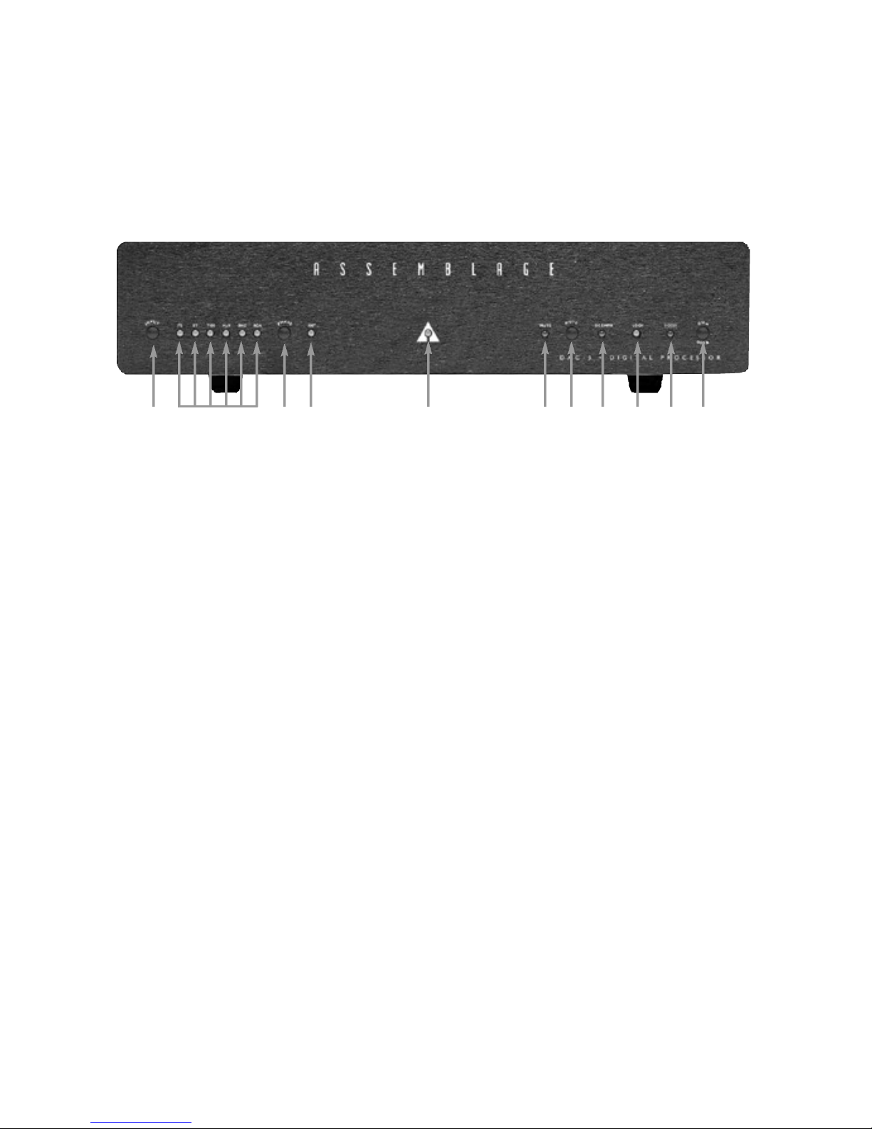
assemblage DAC-3 Instruction sheet

Construction and Operating Manual
A S S E M B L A G E
DAC -3 • DIGITAL PROCESSO R W I TH ®

Dear Assembler,
Thank you for purchasing our 24 Bit/96kHz DAC, the Assemblage DAC-3 Digital Processor kit with
HDCD®.Whether you are an experienced home audio builder, or are new to the hobby of D.I.Y. audio,
we think that you will be very pleased with the sonic results and build quality of our kit. This kit was
designed with ease of assembly and reliability in mind, clearly labeled connections, and complete
instructions.
Contents Page
Parts List..............................................................................................................................................4
Tools Required ....................................................................................................................................8
DAC-3 Functions ................................................................................................................................9
What's going on in your DAC-3 ......................................................................................................11
Wire Stripping....................................................................................................................................14
Soldering............................................................................................................................................14
Parts Layout ......................................................................................................................................18
Assembly Instructions......................................................................................................................20
Non-HDCD®Gain Reduction Selection ............................................................................................21
Input AC Line Voltage Selection ....................................................................................................24
Auto/ Mannual Digital Input Selection ............................................................................................26
System Connection ..........................................................................................................................30
Specifications....................................................................................................................................31
Future Upgrades & Options ............................................................................................................31
Guarantees and Warranty ................................................................................................................31
Schematics ........................................................................................................................................32
Warning and Disclaimer of Liability
When constructing this kit, take care that the assembly steps are followed precisely. Take extra care
when completing Step 6; if these steps are executed incorrectly, damage to the DAC-3 may result when
the unit receives power. Under no circumstances does The Parts Connection or Sonic Frontiers,
International assume liability or responsibility for injury or damages sustained in the operation or
assembly of this equipment, or for damages to any equipment connected to it. If you have any
questions regarding the assembly or set up of the DAC-3, please do not hesitate to contact us.
3

Parts List
The following list of parts are separated into groups, one for each circuit board type and chassis
assembly.This is where the parts will be installed or used. Please check the package to ensure that all
parts listed are present and accounted for.Please note that some substitutions may be made at any time
for a component value that may enhance or will maintain the original circuit operation.
On the same note, if you are planning to install the Signature Parts Upgrade kit at this same time,
take note of the parts labeled “Sig.” in this manual. Refer to the Parts Upgrade Instructions for these
replacement parts.
Parts for the Digital I/P PCB:
Printed Circuit Boards:
1 Digital I/P Board (Partially Pre-assembled)
Qty Item/Value Unit / Reference Designators
Miscellaneous
3 4-24 5/16" Philips XLR and Toslink mounting to chassis
2 4-40 Hex head 3/8" Jack screw Holds the I2S connector
5#4 Black External Tooth Lock Washers I2S, XLR and Toslink mounting to chassis
1 3/8 in x 32 Panel Nut H-P Optical Mounting
4 6-32 1/4" Zinc Screws Holds PCB to Chassis Standoff's
4

Qty Item/Value Unit / Reference Designators
4 #6 Internal Tooth lock washer Under screws
8” (Sig.) Solid Core 22awg Tinned Copper CN103, CN104 Digital Inputs
7.5” (Sig.) Teflon Clear Sleeving 18awg CN103, CN104 Digital Inputs
1 Nylon Spacer H-P Optical Mounting
Parts for the Left & Right O/P Boards:
Printed Circuit Boards
1Left & Right O/P Board Combo (Partially Pre-assembled)
Qty Item/Value Unit / Reference Designators
Output Connectors
4” (Sig.) Kimber Kable TCSS TWpr 19awg R/BK To Audio O/P jacks CN203, CN303
4 4-24 5/16" Philips XLR mounting to chassis
4 #4 Black External Tooth Lock Washers XLR mounting to chassis
8 6-32 1/4" Zinc Screws Holds PCB's to Chassis Standoff's
8#6 Internal Tooth lock washer Under screws
Parts for the Power Supply Board:
Printed Circuit Boards
1 Power Supply PCB (Bare Board)
Qty Item/Value Unit / Reference Designators
Semi-Conductors
2 74HC14 U411, U412
1 CD74HC4017E U408
1 74HC74N U410
1 74HC00 U413
1 ULN2003 U409
2 LT317AT ADJ. U401, U405
2 LT337AT ADJ. U402, U406
1 7805 + 5V Fixed Regulator U407
2 7812 + 12V Fixed Regulator U403, U404
1 LED - Coool Blue T1 LD408 Power Indicator
8 LED - Green T1 LD401-407, LD411, Lock, Phase, Digi in's
3LED - Red T1 LD409, LD410, LD412 Mute, De-Emph, HDCD®
11 1N4002 D417-427
16 (Sig.) SF4002 or HFA4002 D401-416
4 1N4148 D428-430, (D431 under pcb as noted in text)
Capacitors - Electrolytic (Radial)
11µF/50V C459 under pcb as noted in text
12 47µF/25V C435-444, C446, C453
12 3300µF/35V C417-428
5

Qty Item/Value Unit / Reference Designators
Capacitors
1 120pF (C460 under pcb as noted in text)
16 10nF C401-416
17 100nF C429-434, C445, C447-452, C455-458
1 220nF C454
Parts for the Power Supply Board: (Continued)
Qty Item/Value Unit / Reference Designators
Resistors - 1/4 Metal Film 1%
1100R R427
4 243R R401, R404, R409, R412
3 300R R405, R407, R408
2 626R R406, R420
1 1K62 R431(under pcb as noted in text)
1 1K97 R419
4 2K64 or 2K67 R402, R403, R410, R411
1 3K97 R421
1 4K32 R429
3 16K9 R414, R416, R418
6 100K R413, R415, R417, R422, R423, R426
31M5 R424, R425, (R430 under pcb as noted in text)
Switches
3 Right Angle, Tact PCB Mount SW401, SW402, SW403 I/P, Phase, Mute
1 DPST Push On-Push Off SW404 Main Power Switch
Transformers
1 15V 25VA Toroidal TR402
2 18V 25VA Toroidal TR401, TR403
Connections
13 Pin Male Header Single Inline J401
12 Pin Female Shorting Jumper J401 Selects Auto/Manual I/P Scan
310 Pin Ribbon w/1 connector CN401-3 Power to other Brd's
110 Pin Male Dual Inline CN404 Cable to Digital I/P PCB
1 10 Cond. 1 foot Flat Ribbon CN404 to CN106 connection
Cable w/connectors
Miscellaneous
6 Heat Sink Single TO-220 U401-6 Voltage Reg's
4 Teflon Shoulder Washer U401, U402, U405, U406
6 Silpads U401-6 Voltage Reg's
1800 mA, & 400mA SLO BLO Fuses F101 (only one used, see text)
1 pr. 5x20 Fuse Clips PCB M't. F101
6

Qty Item/Value Unit / Reference Designators
1 Fuse Cover Boot F101
1 in Heat Shrink Tubing R431
Hardware
64-40 X 3/8" philips PH SS Screws U401-6 Heatsinks
6 #4 Kepnuts U401-6 Heatsinks
9 6-32 1/4" Zinc Screws Holds PCB to Chassis Standoff's
9#6 External Tooth lock washer Under Screws
Qty Item/Value Unit / Reference Designators
Main Chassis Components:
1 Main Chassis
1 Main Chassis Top Cover
1 Front Panel - Aluminum
3 Tact Button Scan I/P, Phase, and Mute
1 Plunger Button For Power Switch
Chassis Mounted Hardware
1 (Sig.) RCA Female Jack - RED CN303 Audio O/P Right
1 (Sig.) RCA Female Jack - WHITE CN203 Audio O/P Left
1 (Sig.) RCA Female Jack - BLACK CN104 S/PDIF I/P
1 BNC Male, Chassis Mt. 75 Ohm CN103 S/PDIF I/P
1 IEC Filtered Socket AC Input
4 E. A. R. - Mounting Feet Chassis Feet
Chassis Assembly Hardware
14 4-40 1/4" Blk Counter Sunk Holds Top Cover
24-40 X 3/8" Philips PH SS - Blk Holds IEC to chassis
2 #4 External Tooth lock washer - Blk Under IEC Screws
2 #4 Kepnuts Holds IEC to chassis
1 6-32 1/4" Zinc Screws IEC AC Safety Ground to chassis
4 6-32 1/2" Screws Feet to Chassis
3 M4 x 6 Screws Holds Transformers
3 M4 Washers Holds Transformers
1 #6 3/4" Solder Lug IEC AC Safety Ground to chassis
4 #6 Flat washer Feet
2 #10-32 Kepnuts Holds Front Panel to chassis
Miscellaneous
10 ft WonderSolderTM Silver Solder
1 ft Solder-wick
1 Detachable AC power cord
1Construction and Operation Manual (If you have made it this far, chances are it's here!)
1 Warranty Card - Remember to return this card.
7

Tools Required
In addition to the parts supplied in the kit, you will need any or all of the following tools to complete
the construction of the DAC-3 kit.
1 Solder Sucker
1 Pencil tip soldering iron of good quality (900oF tip temperature max.)
1 #1 Philips screwdriver
1 #0 Philips screwdriver
110mm wrench, nutdriver or ratchet (3/8" will also work)
1 12mm wrench, nutdriver or ratchet (1/2" will also work)
1 14mm wrench, nutdriver or ratchet (9/16" will also work)
16" crescent wrench (adjustable wrench)
1 Pair of fine tipped needle nosed electronics pliers
1 Pair of regular needle nosed pliers
1 Pair of regular pliers
1 Wire stripper or hobby-knife (If you trust yourself with your fingers!)
1Wire side cutters
1 Ruler/Scale (not shown)
8

DAC-3 Functions :
A - Source Selector Tactile Button
This button will activate a manual or automatic
advancement to the next digital source input.(See page
25 for setup.)
B - Source Selector LED's
These LED's indicate which digital source input is
currently selected - either the I2S,ST-Optical,TOSLINK-
Optical, AES/EBU, Coaxial-BNC, or Coaxial-RCA.
C - Phase Tactile Button
Reverses the absolute polarity of the Analog Output
Signals.
NOTE ON PHASE SELECTION:
The phase inverts the absolute polarity of the analog
output (A positive signal becomes a negative signal).
This can be used to compensate for recordings with
inverted polarity. The correct phase for a recording can
be found by playing a CD in both phase positions.When
absolute polarity is correct the music will be more
precise, with a wider, deeper soundstage.
D - Phase LED
This LED will indicate the currently selected phase
polarity. When lit, the absolute phase is inverted 180
degrees.
E - Power LED
This coool blue LED will light when the DAC-3 is
plugged in and switched on while receiving AC power.
F - Mute LED
Muted conditions of all the audio O/P's are indicated by
this LED.While lit this indicates that the audio O/P's are
muted. This Mute LED comes on during digital I/P
scanning, or when no active digital source is connected
and received by the DAC-3, (In both cases, no Lock
condition also applies.)
G - Mute Tactile Button
Depressing this button will active the muting relays for
each audio channel and signal phases, allowing no
audio from any of the audio O/P's as indicated by the
Mute LED above.
H - De-emphasis LED
This LED lights when a digital source is recorded with
the standard CD pre-emphasis of 50/15 microseconds.
(This LED rarely comes on.)
I - Lock LED
This LED indicates when a signal from a digital source,
with a sampling rate of 32kHz to 96kHz, is being
properly received.
G - HDCD®LED
Lights when an HDCD®encoded Disc is played into the
DAC-3.
H - Power Switch Button
The switch is a push-on push-off type button.The power
to the DAC-3 is completely turned off while the switch is
in the out position.
BA C HGIHGFED
9

Connection Functions
I - AC Power Cord Socket
Plug in the female end of the detachable power cord
here.
J - XLR - Audio Output Right Channel
Balanced XLR Output connects to a balanced right
channel line input on a preamplifier, integrated amplifier,
or receiver.
K - RCA - Audio Output Right Channel
Un-balanced RCA Output connects to an un-balanced
right channel line input on a preamplifier, integrated
amplifier, or receiver.
L - S/PDIF Coaxial - RCA Input
Plug in a digital source that has a Coaxial digital output
with RCA connectors.
M - S/PDIF Coaxial - BNC Input
Plug in a digital source that has a Coaxial digital output
with BNC connectors.(75 Ohm characteristic impedance).
N - Optical-ST Digital Input
Plug in a digital source that has a ST-Optical digital
output here.
O - Optical-Toslink Digital Input
Plug in a digital source that has a Toslink Optical digital
output here.
P - AES/EBU Digital Input
Plug in a digital source that has an AES/EBU digital
output with XLR connectors. (110 Ohm characteristic
impedance).
Q - I2S Digital Input
Plug in a digital source that has a I2S digital output here.
(13W3 connector).
R - RCA - Audio Output Left Channel
Un-balanced RCA Output connects to an un-balanced
left channel line input on a preamplifier, integrated
amplifier, or receiver.
S - XLR - Audio Output Left Channel
Balanced XLR Output connects to a balanced left
channel line input on a preamplifier, integrated amplifier,
or receiver.
IJKN QPO
L M
RS
10

What’s going on in your DAC-3
Pacific Microsonics
PMD-100 Digital Filter
and HDCD®Decoder
IEC AC Input Filter -
filters out high frequency
components in AC line
voltage - also prevents
digital noise from getting
out to the AC line
Potted Dual
Secondary Toroidal
Power Transformer -
for lower emitted magnetic
field and noise
Power Supply Filter
Caps - to smooth raw
DC voltage
Auto / Manual Digital
Input Selector
Crystal CS8414 Input
Receiver-reclocks incoming
digital signal
Left DAC Output PCB
4 layer
Right DAC Output PCB
4 layer
Digital Input PCB
4 layer
DC Servo stage
nulls out DC offset of
I/V converter
Output Muting Relay
(Shunt configuration)
Non-HDCD gain
reduction disable/enable
jumper
Dual ISO-150 Isolate
the digital ground noise
from the DAC output
boards
AC input voltage
selection jumpers
Power Supply PCB
2 layer
LT1357 I/V Converters -
converts current
output of DACs to
a voltage output
24 Bit Resolution Burr-Brown
PCM 1704 DACs (2 per channel) -
converts digital data stream into
analog wave form by quantizing each
sample into a discrete AC current

Before-You-Start Kit Overview
Before you start assembling your DAC-3, please take a few minutes to read this preface on the
construction manual and the kit.
Zen and the Art of Electronics Assembly:
Assembling a high quality electronic device requires a certain frame of mind.The object is not to rush
through and get the kit assembled as quickly as possible, but to methodically and correctly put together
the pieces of this audio jigsaw puzzle.The kit could take as long as 4-6 hours to complete, so plan your
attack accordingly and take breaks often, you will find the natural places to do so as you go through the
assembly steps.The final kit appearance will benefit from your rested mind.
Clues:
If the instructions are followed to the letter, this DAC will work correctly right from the start. If you try to
assemble the kit purely from the pictures/illustrations without reading the body of the text, your unit will
most likely not work.
Please note that this kit is not intended for the complete novice. A certain level of competency is
assumed in electronics assembly - i.e. the ability to solder, and follow instructions. The use of a
voltmeter/multimeter may become an added asset.
Parts Count:
The parts for your Assemblage kit have been packaged into several groups: capacitors, resistors, semi-
conductors, and hardware. Each component type is individually packaged to allow for ease of
identification.
While every precaution has been taken to ensure that you have received a complete kit, your kit has
been picked and packed by humans.Therefore, please use the Parts List starting on page 4, to ensure
that you have all parts present and accounted for. Before you convince yourself that something is
missing, check again! Large cardboard boxes are notorious for hiding small parts, as are the packing
materials.
General Instructions:
Where necessary a simple overview of the upcoming step is presented to you before you actually do
that procedure. This little preamble will help to clarify the next assembly step and give you a broader
understanding of the construction methods to use, and hopefully aid you in getting it right the first time.
Following this is a list of the parts or components that will be needed or constructed in this immediate
section, then a detailed description of the assembly procedures for that section.
The top of the printed circuit boards is the one side that has the white silk-screening on it.Therefore you
know that the backside has no screening on it, and no parts, accept for the enhancements to the Power
Supply PCB.
Stuffing the PC Boards:
The process of stuffing the main board with parts is in fact a relatively simple procedure - Generally the
sequence will be to simply obtain the bag containing the appropriate part, carefully bend the leads,
12

place the part into the holes in the PC board, then solder and trim the leads. (Please review our
soldering instructions on the 14 page).
If you inspect the boards, you will notice that all parts locations have been labeled with the appropriate
part reference designator. Each different set of components has been placed in its own individual bag,
which has its own label and also listing the part type. (You will find the reference designators listed on
the Parts List.) Therefore, when you are asked to install the resistor R1, you simply procure the labeled
bag with that part in it. Once the part is installed and soldered in place, you can check that component
off the supplied checklist in this manual. There are also several photos and diagrams detailing parts
placement to reduce any possible confusion that may arise regarding parts placement.Please note too,
that there may be some subtle differences between some of the parts shown in the photographs and
those supplied with your kit. On occasion, our technical staff may substitute parts with ones of equal or
higher quality.
NOTE:Talking about part substitutions, there is a Signature parts upgrade kit available for the DAC-3.
(see page 31 for details)
Mechanical Assembly:
The DAC-3 has been designed with ease of assembly in mind. To this extent, the chassis has been
designed with built-in standoffs, to which the PC boards are attached.This allows the PC boards to be
easily installed and removed.
There is a minimum of wiring involved in putting this kit together. Generally - the IEC socket connects to
the power supply board, - the digital S/PDIF input connectors and the audio output RCA jacks are wired
to their respective boards, - and the connection of a few ribbon cables to interconnect the 4 circuit
boards.
Please be sure to follow the installation instructions closely, because some important mounting detail
etc. may be included in any step.
Wire Stripping:
Unless otherwise instructed elsewhere in this manual, the normal procedure to 'prepare' a cut wire is as
follows;
- Trim or cut the wire to the desired length.
-Strip back the wire jacket 3/16" (~5mm), to expose the wire inside. Use your favorite tool, the knife or
wire strippers. If you are using the knife, please be careful and read the instructions on the following
page.
- Twist the wire strands to gather them together and then solder them. This is called the 'tinning
process'.
13

If a lead bender is not being used, hold the
component (resistor, capacitor, LED,...) with a
pair of needle nose pliers and bend the leads to
the appropriate width so it can fit through the
donut pads in its position on the circuit board.
DO NOT bend the leads by applying pressure to
the component, bend by pushing directly on the
lead.
Position the component on the circuit board and
hold it in position as you bend the leads out.
To help conduct the heat from the soldering
iron, “tin” the tip of iron by applying a touch of
solder to the already heated iron tip.
14
If you own a wire stripper, we’re assuming you know how to use it. If not, and you are new to the world
of audio construction, you can use a hobby knife to do the same job. Simply cut around the insulation
leaving an appropriate length for the lead, be very careful to cut only the insulator and not the wire itself.
Pull the excess insulation away and you have your lead. If the wire is made of strands, twist the lead
between your fingertips to keep it from fraying.
Wire Stripping with a Knife:
Soldering:
Let it be said once, to get it out of the way - all soldering must be done with rosin core solder! There is
no warranty on equipment in which acid core solder has been used. Please use the silver solder
provided in the kit. On this note, please review the following pages.

Push the soldering iron tip against the lead and
the foil donut pad on the circuit board and hold for
2 or 3 seconds.Then apply the solder to the other
side of lead, also touching the donut pad.Let the
heated lead and pad melt the solder, not the iron
tip. The solder should flow around the lead.
Remove the iron and solder and let the
connection cool.Trim off the excess lead.
When done CORRECTLY, by heating the lead
and foil donut pad simultaneously, the solder
should flow outward, gradually blending from the
lead to the foil.
When done INCORRECTLY, by just heating
the foil pad and not the lead, a hard rosin bead
will surround the lead, insulating it from the
connection.
An INCORRECT solder is also done by just
heating the lead and not the foil pad.Here a hard
rosin bead forms on the pad, insulating it from the
lead.
To correct these unacceptable solder joints
reheat and if necessary apply a little more solder.
HINT:It is handy to keep a damp sponge nearby
to clean the iron’s tip after each joint is
completed.
Solder Bridges -solder bridges usually happen when too much solder is used, or the solder is dragged
from one connection to another when heat is applied. If a bridge develops, turn the circuit board upside
down and reheat the connection, allowing the solder to flow onto the iron tip. Then resolder the
connections as before, being careful that just enough solder is used to make a connection.
15

16
Parts Layout: (Power supplies and Controls)

17

18
Parts Layout:
Left DAC Output Digital

19
Right DAC OutputInput

Remove Paint on these
stands-off tops
Assembly Instructions:
PC Board Preparations:
I know that you are more than ready to go, so lets now get
right to preparing the printed circuit boards, (PCB's).
Locate the Left and Right output combo board.Now with the
pair of regular pliers, snap off the top edge and bottom edge
end rails from the left and right output boards. Work along
the edges to break off the rails.
Collect all the 4 boards for this DAC-3 kit, they are as follows;
-Power Supply PCB,
- Left Channel DAC Output board,
- Right Channel DAC Output board,
- Digital Input board.
Using your file - debur the edges of all the boards as
necessary.
Step 1A:
Chassis Preparations:
Originally I was going to start by working on the
circuit boards, then I thought, why not install the
boards into the chassis as soon as they are done?
That way they will be keep out of harms way for the
longest period of time.
With this in mind, lets prepare the chassis for
installation of the circuit boards.
-If you are installing SignatureParts Upgrade Kit
Soundcoat, this is a great time to refer to the
Upgrade kit Instruction and install the Soundcoat
on to the chassis.
-To keep digital noise to a minimum, it is important
to have a good chassis ground connection at all
points needed.Refer to the photo for the chassis
stand-offs that needed to be masked or cleared of
paint during the painting process. The paint will
easily scrape off the tops of the indicated points if
they are not clear already.
✓
20

21
Step 1B:
On the underside of the chassis there are
provisions to screw mount the E.A.R. feet.
4x E.A.R. Feet
4x 6-32 1/2" Philips SS screws
4x #6 Flat washers
Using a washer under each screw, attach the 4
feet to the bottom of the chassis.The screws need
not be very tight to hold them in place.You'll see.
Step 2:
1x RCA Female Jack - White CN203 Audio
O/P Left (Sig.)
1x RCA Female Jack - Red CN303 Audio
O/P Right (Sig.)
- Install the two panel mount RCA jacks into the
chassis from the outside. The RED striped
RCA jack is for the RIGHT channel and the
WHITE for the LEFT channel.
-The proper order for the washers is one
shoulder washer against the RCA jack, then
the chassis panel sandwiched between it and
the second washer, the ground lug tab next,
and then the nut on the inside.
-Orient the RCA jack so that the opening for the
signal wire in the center of the jack faces up,
hold the outside of the RCA jack with a 12mm
wrench or pliers, and tighten the inside 12mm
nut.Bend the ground lug slightly forward to the
inside of the chassis.This will make it easier to
solder later.
Note: I am sorry for the loose fit of the RCA jacks
and the extra care necessary to mount these
parts. The chassis hole needs to be large enough
to fit the Signature Upgrade part, the Kimber Ultra-
Plate RCA jacks.
Step 3:
1x RCA Female Jack - Black CN104 S/PDIF I/P
(Sig.)
1x BNC Male, Chassis MT CN103 S/PDIF I/P
-The RCA jack mounts in the same fashion as
the RCA's for the audio O/P's.The ground lug
needs to point, like on a clock face, to the 7:30
position and bent inwards as well.
-The BNC connector is mounted in the 'D'
shaped hole from the outside of the chassis,
with the nut and washer on the inside of the
chassis.
Step 4A:
Digital Input Board:
Starting with the 4 layer Digital Input PCB, see the
photo below, we will mount the last few remaining
parts, set the HDCD®gain attenuation setting of
your preference, and then into the chassis it goes.
You may have noticed that the circuit boards are
not all completely stuffed. After all this is still a kit
right? The parts needed in this step are;
1x 1 foot Flat Ribbon Cable w/connectors
8” Solid Core 22awg Tinned Copper wire (Sig.)
7.5” Teflon Clear Sleeving 18awg (Sig.)
1x 3/8” x 32 panel nut
4x 6-32 1/4" Philips Zinc Screws
4x #6 Internal tooth lock washer
3x 4-24 5/16" Philips
2x 4-40 Hexhead 3/8" Jack screw
5x #4 Black External Tooth Lock Washers
1x Nylon spacer
-The locations of these parts will be easy to
find by looking at the outlines on the board
itself, and as always the Reference Designator
is there on the PCB to further aid you in
locating the parts' home position.
-The ribbon cables are marked with a black line
down one side to indicate pin #1. Install the
cable with the black edge to pin #1 on the
PCB.
-HDCD®GAIN SCALING - Due to popular
demand, the installation of the 2 pin Shorting
Jumper on J102 is up to you.This is where you
select the HDCD®gain attenuation settings
you prefer. The PCB descriptor is self-
explanatory, but I will not assume anything!
(You may know why!) If you do not want the
audio O/P level to change +6dB when you play
a HDCD®recorded CD, compared to a
standard CD, then you place the Shorting
Jumper so that it straddles the left 2 male pins
on J102 (FIXED). Conversely, if you do want
the audio O/P level to track the different CDs'
Table of contents
Popular Music Equipment manuals by other brands

Vintage Revolution
Vintage Revolution PedalPro owner's manual

Roland
Roland MV-8000 Specifications

Roland
Roland S-0808 features and benefits

Yamaha
Yamaha DTX-Multi 12 Service manual

Wenger
Wenger Flex TechBridge Assembly instructions and owner's manual

Monitor Audio
Monitor Audio platinum series II instruction manual