manuals.online logo
Brands
  1. Home
  2. •
  3. Brands
  4. •
  5. Extron electronics
  6. •
  7. Music Equipment
  8. •
  9. Extron electronics MVC 121 Plus User manual

Extron electronics MVC 121 Plus User manual

IMPORTANT:
Go to www.extron.com for the
complete user guide, installation
instructions, and specifications.
MVC 121 Plus • Setup Guide
The Extron MVC 121 Plus is an audio mixer and volume controller that will mix up to two mono mic/line inputs (balanced/
unbalanced) with one stereo line level input (balanced/unbalanced). All audio input signals are converted from analog to digital
prior to processing or routing. Each mic/line input and the line level input have their own gain control adjustment screws. The
mixed variable output also features a volume control knob on the front panel.
NOTE: For full installation, configuration, and operation details, see the MVC 121 Plus User Guide, available at
www.extron.com.
Rear Panel Features and Connections
a12 VDC power connector fFixed output connector
bMic 1 and 2 Phantom power LED gRS-232 connector
cMic/Line input connectors (1 – 2) hDigital input connector
dLine input connector (3) iReset button
eVariable output connector
Installing the MVC 121 Plus
1. Disconnect power from all equipment.
2. (Optional) Mount the unit to a rack or furniture.
3. Connect the audio inputs.
• Connect up to two balanced or unbalanced mono mic/line level input devices to
connector cabove (see the 6-pole wiring diagram on the right). Alternatively,
two 3-pole connectors may be used.
• A balanced or unbalanced stereo line level input may be connected to dabove (see the 5-pole wiring diagram below).
Balanced audio
Tip
Ring
Tip
Ring
LR
Slee
ves
Unbalanced audio
Tip
Sleeve
Sleeve
Tip
LR
Do not tin the wires!
4. Connect the audio output.
• For variable balanced or unbalanced stereo output controlled
by the front panel knob of the MVC 121 Plus, connect an
amplier to the Variable connector e, above (see the wiring
diagram on the right).
• For xed stereo output, connect an output device to Fixed
connector f(see the wiring diagram above).
5. Connect a control device. Connect a host device, such as a computer, to
one of the following MVC ports to congure and control the MVC 121 plus via
Simple Instruction Set (SIS™) commands.
• RS-232 port (rear panel) — Connect a host device to the Tx, Rx, and
_(ground) pins of this 6-pole captive screw connector (g). The default
baud rate for this port is 38400 baud, 1 stop bit, no parity, 8 data bits, and
no ow control (see the wiring diagram on the right).
• Config port (front panel) — See Front Panel Features on the next page.
6. Digital input connector. Up to three congurable input ports (see hon the
rear panel diagram above) allow connection to various devices including motion
detectors, alarms, buttons, photo (light) sensors, and temperature sensors. This
connector shares a common ground with the RS-232 connector (see the wiring
diagram on the right).
Both the RS-232 and digital input connectors may be used simultaneously by
using a 6-pin captive screw connector with two wires sharing the ground connector
(see the diagram on the right).
12MIC/LINE
Balanced MIC
Unbalanced MI
C
Jumper
Unbalanced Stereo Output
Tip
NO GROUND HERE.
Slee
ve(s)
Tip
NO GROUND HERE.
Balanced Stereo Output
Tip
Ring
Sleeve(s)
Tip
Ring
LR
LR
Left
Right
Left
Right
Do not tin the wires!
Transmit (Tx)
Receive (Rx)
Ground (Gnd,
)
RS-232
21
Tx Rx
DIGI IN
3
Do not tin the wires!
1
2
3
_
RS-232
21
Tx Rx
DIGI IN
3
2
1
+48V
MIC
12MIC/LINE
LINE 3
LRRL
POWER
0.4A MAX
12V
RS-232
VARIABLE
FIXEDLR DIGI IN
MVC 121 Plus
Tx Rx 1 2 3
INPUTS OUTPUTS
RESET
123
4 5
67
9
8
RS-232 DIGI IN
Tx Rx 1 2 3
68-1937-50 Rev. B
10 13
Extron USA Headquarters
+1.800.633.9876 (Inside USA/Canada Only)
Extron USA - West: +1.714.491.1500 FAX: +1.714.491.1517
Extron USA - East: +1.919.850.1000 FAX: +1.919.850.1001
© 2013 Extron Electronics — All rights reserved. All trademarks mentioned are the property of their respective owners. www.extron.com
MVC 121 Plus • Setup Guide (continued)
7. Reset button. The recessed reset button (see ion the rear panel diagram
on the previous page) is used to access various modes of resets. The green
power LED on the front panel indicates the reset mode that was used.
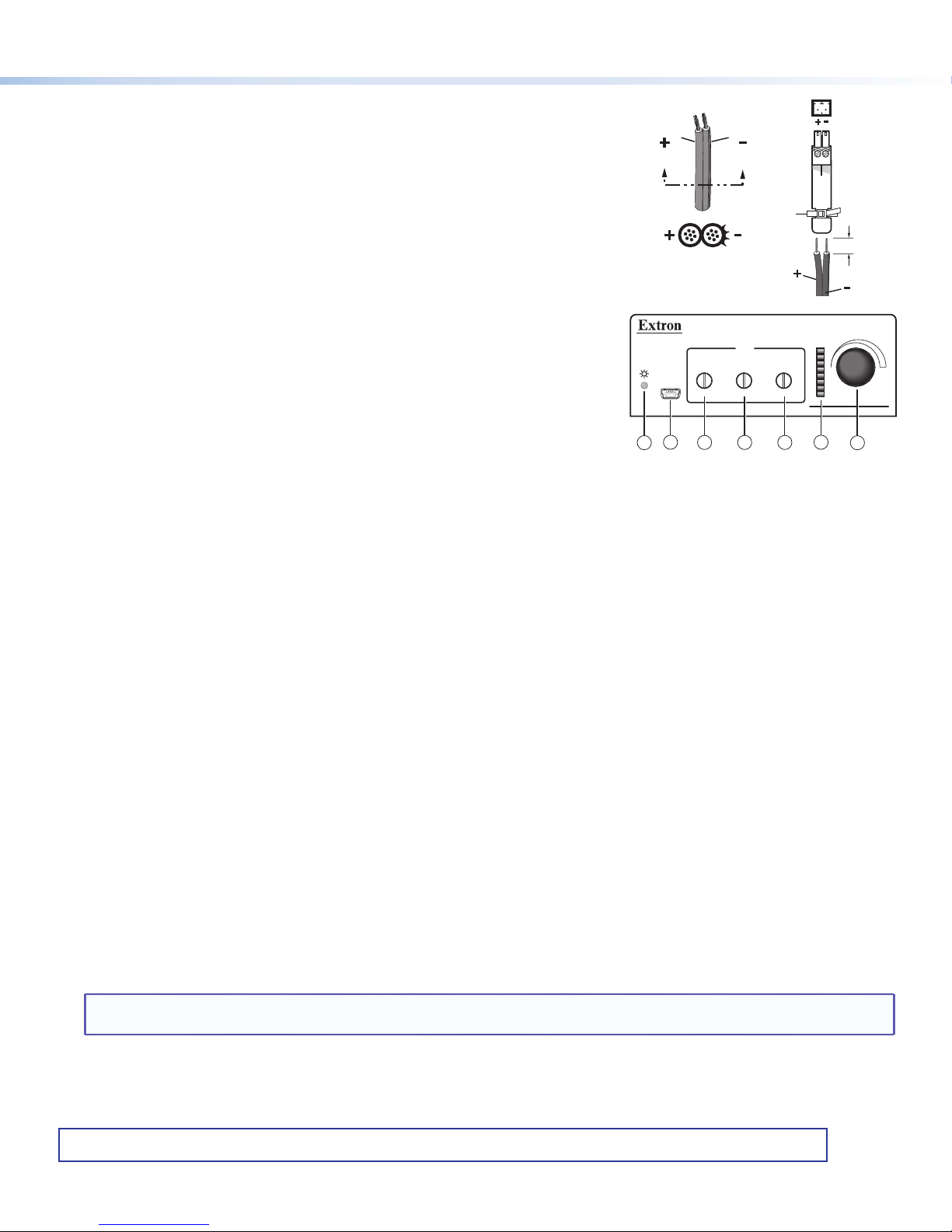
8. Connect power to the MVC by connecting the included 12 VDC external
power supply to the rear panel power connector (see aon the rear panel
diagram). The wiring diagram is shown on the right.
9. Install the software. Conguration and control is done via both hardware
encoders and software. The control software, DSP Congurator, is available
at www.extron.com (see Software and Manual Download from the Website
below). The control software help le contains operation descriptions.
Front Panel Features (see the front panel diagram at right)
aPower/Reset LED — This power indicator lights green when the MVC 121 Plus
is operational. The LED also blinks per mode reset.
bConfiguration (Config) port — Connect a PC to the USB Mini-B connector for
conguring the MVC using the DSP Congurator Software. The MVC 121 Plus
USB driver must be installed prior to using this port.
cMic 1 input gain control — Rotating the encoder screw clockwise increases the gain setting. Rotating the encoder screw
counterclockwise decreases the gain. This adjustment controls the single gain point in the mix matrix that mixes mono mic 1
levels to the stereo output bus.
dMic 2 input gain control — Rotating the encoder screw clockwise increases the gain setting. Rotating the encoder screw
counterclockwise decreases the gain setting. This adjustment controls the single gain point in the mix matrix that mixes
mono mic 2 levels to the stereo output bus.
eLine level input 3 gain control — Rotating the encoder screw clockwise increases the gain setting. Rotating the encoder
screw counterclockwise decreases the gain setting. This adjustment controls the single gain point in the mix matrix that
mixes line level input 3 to the stereo output bus.
fLED ladder indicator bar — As the mix-point gain or output volume increases or decreases, the LED indicator bar lights
from the bottom to the top to indicate the current mix-point or volume level. As the volume is increased or decreased within
a volume range, the top lit LED ashes once. If the knob is turned past maximum volume, all 8 LEDs ash for as long as the
knob continues to be turned. After 3 seconds of inactivity, the knob controls the variable volume output.
gVolume level adjust knob — Rotating the adjustment knob clockwise increases the output volume. Rotating the knob
counterclockwise decreases the volume.
Software and Manual Download from the Website
1. Using any internet browser, go to www.extron.com.
2. From the Extron home page, select the MVC 121 Plus from the Product Shortcuts drop-down menu.
3. Select the Downloads tab on the MVC 121 Plus product page.
4. Select the User Guide from the list of available documentation and click on it to either view or download it to the hard drive
for future reference.
5. To download the control software, on the Downloads tab select DSP Configurator.
6. The link navigates to the selected software download page. Fill out the form, then download the software to the hard drive.
NOTE: On the first installation of DSP Configurator, the USB driver loads automatically. Follow the on-screen instructions.
Once the USB driver has loaded, DSP Configurator continues to load.
By default, the program installs in C:\Program Files\Extron\DSP Congurator and an icon is placed on the desktop.
SECTION A–A
Power Supply
Output Cord
Ridges
A
Smooth
A
Ridges
Smooth
2-P
ole Orange
Captive Scre
w
Connector
(12V)
Tie Wrap
3/16”
(5 mm) Max.
VOLUME
CONFIG
MIX
MICMIC LINE
321
MIXER/VOLUME CONTROLLER
MVC 121 Plus
2
13 4 5 67

Other manuals for MVC 121 Plus

3

Other Extron electronics Music Equipment manuals

Extron electronics PowerCage FOX AEX 104 User manual

Extron electronics

Extron electronics PowerCage FOX AEX 104 User manual

Extron electronics FOX AEX 108 User manual

Extron electronics

Extron electronics FOX AEX 108 User manual

Extron electronics AXP 50 C AT User manual

Extron electronics

Extron electronics AXP 50 C AT User manual

Popular Music Equipment manuals by other brands

Fishman ELLIPSE AURA - user guide

Fishman

Fishman ELLIPSE AURA - user guide

Komet Aero 33 owner's manual

Komet

Komet Aero 33 owner's manual

Neumann KM D AES 42 brochure

Neumann

Neumann KM D AES 42 brochure

Mod K-700 instructions

Mod

Mod K-700 instructions

Millennia HV-32P user guide

Millennia

Millennia HV-32P user guide

Amumu NEO-SP30 owner's manual

Amumu

Amumu NEO-SP30 owner's manual

Trident A-Range owner's manual

Trident

Trident A-Range owner's manual

Channel Vision AB-404 instructions

Channel Vision

Channel Vision AB-404 instructions

DFI Clockwork V2 Delay user manual

DFI

DFI Clockwork V2 Delay user manual

APART ZONE4 Manual guide

APART

APART ZONE4 Manual guide

Sony DWR-R02D user guide

Sony

Sony DWR-R02D user guide

Akai MPC 2500 Service manual

Akai

Akai MPC 2500 Service manual

AxelTech OXYGEN 3000 PLUS user manual

AxelTech

AxelTech OXYGEN 3000 PLUS user manual

Yamaha FB-01 Service manual

Yamaha

Yamaha FB-01 Service manual

Xaoc Devices ZAGRZEB Operator's manual

Xaoc Devices

Xaoc Devices ZAGRZEB Operator's manual

Noise Engineering Polydactyl Versio instruction manual

Noise Engineering

Noise Engineering Polydactyl Versio instruction manual

Silver Apt Stream-In user manual

Silver Apt

Silver Apt Stream-In user manual

BlueChip Baby b. user manual

BlueChip

BlueChip Baby b. user manual

manuals.online logo
manuals.online logoBrands
  • About & Mission
  • Contact us
  • Privacy Policy
  • Terms and Conditions

Copyright 2025 Manuals.Online. All Rights Reserved.