P.5
50+ EXPERIMENTS
1. Simple LED circuit
2. Spinning LED light
3. Function of the reed switch
4. Demonstration of resistance and current
5. Resistors in series connection
6. Resistors in parallel connection
7. Function of the touch plate
8. A simple demonstration of a function of the PNP transistor
9. A simple demonstration of a function of the NPN transistor
10. Two LEDs in parallel connection
11. Three LEDs in parallel connection
12. LED and spinning LED with a single switch
13. LED and spinning LED with separate switches
14. Basic circuit operation of LED
15. Spinning LED light in advance circuit operation of LEDs
16. LEDs combination
17. Function of a diode
18. A simple demonstration of the light sensor
19. A practical example: Light triggered LED
20. A practical example: Darkness triggered LED
21. Demonstration of a simple function of SCR
22. A practical example of SCR
23. Digital segment LED displaying“1”
24. Digital segment LED displaying“2”
25. Digital segment LED displaying“8”
26. Digital segment LED displaying“F.”
27. Digital segment LED switching between“1” and “8”
28. Digital segment LED switching between “I”, “L” , “F” and “E”
29. Light control seven-segment LED display – C (Dark Type)
30. Light control seven-segment LED display – E (Light Type)
31. Flashing LEDs
32. Dog barking sound with ashing LED
33. Dog barking sound and ashing digit “1”
34. Rooster crowing sound and ashing digit“2”
35. Cat meowing sound and ashing digit“3”
36. Horse neighing sound and ashing digit “4”
37. Bird chirping sound and ashing digit“5”
38. Duck quacking sound and ashing digit “6”
39. Sheep baaing sound and ashing digit “7”
40. Cuckoo calling sound and ashing digit“8”
41. Frog croaking sound and ashing digit “9”
42. Manual control horse neighing sound with push switch control ashing
digit “0”
43. Magnet control sheep baaing sound with ashing LED
44. Touch control rooster crowing sound with ashing LED
45. Light control cat meowing sound with ashing LED
46. Darkness activated dog barking sound
47. Security alarm based on wiring disconnection
48. Water level LED alarm
49. Light intensity indicator
50. Darkness activated spinning LED light
51. Light control spinning LED light
Adult supervision and assistance is required.
This unit is only for use by children aged 8 years and older.
Not suitable for children under age 3 years old due to small part(s) and
component(s) – CHOKING HAZARD.
Read and follow all instructions in the manual before use.
This toy contains small parts and functional sharp points on components. Keep away
from children under age 3 years.
2 x AA size batteries are required (not included)
Please retain the information and this manual for future reference.
Instructions for parents are included and have to be observed.
WARNING! Not intended for children under 8 years. This product contains (a) small
magnet(s). Swallowed magnets can stick together across intestines causing serious
injuries and death. Seek immediate medical attention if magnet(s) are swallowed or
inhaled.
This toy contains functional sharp points on component leads and wires, requiring
care when handling.
Warning. Do not use close to the ear! Misuse may cause damage to hearing.
WARNING
Before setting up any experiment, please double check and make sure all
wiring connections you have made are correct before inserting the batteries
and switching on the unit, as failure may result in damage to components or
circuit board unit.
When experiment is nished, make sure the batteries are disconnected and
switch o the unit before you clear away the wires.
Do not apply any components or parts to the experiment other than those
provided with this kit.
If this product malfunctions or "locks up", try switching o and back on
again or removing and re-inserting batteries.
Do not lock the motor or other moving parts. Otherwise it may cause
overheating.
The toy is not to be connected to more than recommended number of power
supplies.
CAUTION !
Ensure all wires are correctly connected to the numbered spring terminals of the
main circuit board unit as stated wiring sequence of each experiment
Bend the spring terminal over and insert the exposed shiny conductor part of
wire into spring terminal. Make sure the wire is securely connected to spring
terminal.
For example if the wiring sequence is 4-33, 1-10-32-35, 2-12, then rst connect a
wire between spring terminal 4 and 33; next connect a wire between spring
terminal 1 and 10, and then a wire between spring terminal 10 and 32, a wire
between spring terminal 32 and 35, and nally connect a wire between spring
terminal 2 and 12. This is an example to demonstrate wiring connections only,
not an exact circuit connection in the experiment.
If the circuit does not work, check the wire and spring terminal connection to
see whether it is probably not well connected or the insulated plastic part of a
wire is inserted to spring terminal.
Use 2 x AA size batteries (not included)
For best performance, always use fresh batteries and remove batteries when not
in use
Batteries must be inserted with the correct polarity
Non-rechargeable batteries are not to be recharged
Re-chargeable batteries are only to be charged under adult supervision
Re-chargeable batteries are to be removed from the toy before being charged
Dierent types of batteries or new and used batteries are not to be mixed.
Exhausted batteries are to be removed from the toy
The supply terminals are not to be short-circuited
Only batteries of the same or equivalent types are to be used
Do not dispose of the batteries in re
Do not mix old and new batteries
Do not mix alkaline, carbon zinc and re-chargeable batteries
The overall aim for this electronic circuit kit is for you to get a better understanding of how connecting dierent wiring sequence will make dierent science
experiments. Each experiment is targeted at dierent basic concept of electronics & electricity. Please make sure to read carefully and all wires are correctly
connected in the indicated diagram in order to have each experiment work.
BATTERY INFORMATION
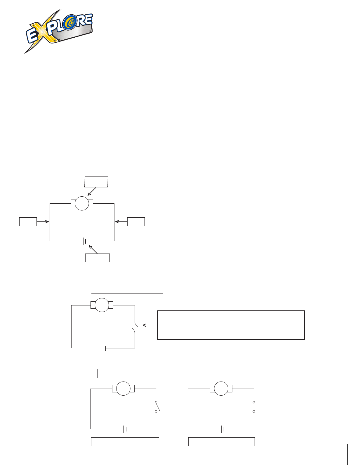
Objective :
WIRING SEQUENCE AND CONNECTION