Alpine DC Power Supply Installation Notes 5
Installing the Alpine 3808 Power Supply
8If you are going to install a replacement power supply, follow the installation steps on
page -3.
9Leave the ESD strap permanently connected to the chassis, so that it is always available
when you need to handle ESD-sensitive components.
Installing the Alpine 3808 Power Supply
To install a DC power supply in the Alpine 3808 switch:
1Attach the ESD strap that is provided to your wrist and connect the metal end to the ground
receptacle that is located on the top-right corner of the switch front panel.
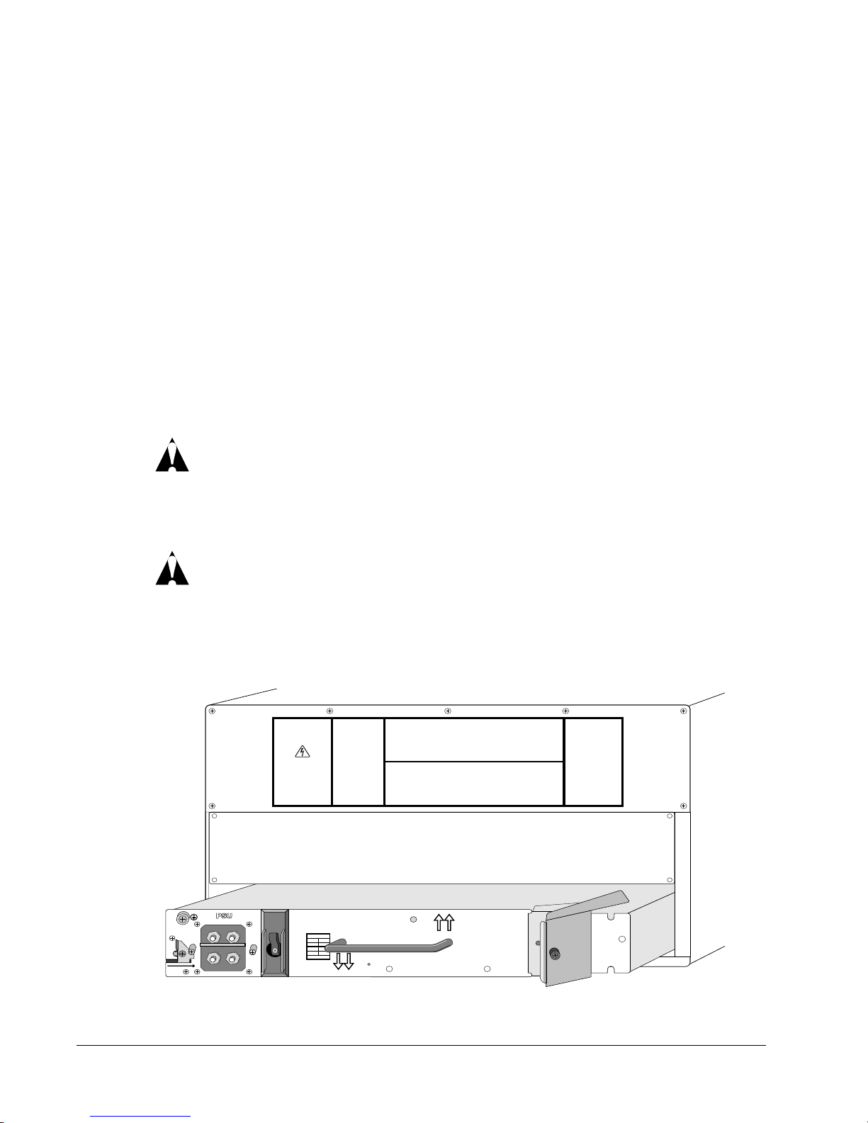
2Ensure that the following is true:
—The power supply is oriented correctly using the text on the front of the power supply
—The ejector/injector lever is open
—The safety latch is in the remove position
—The breaker is in the off position
Caution: When you insert a power supply, use one hand to support the power supply
from the bottom and the other hand to hold the central handle on the front of the power
supply. Do not use just the ejector/injector lever to insert a power supply.
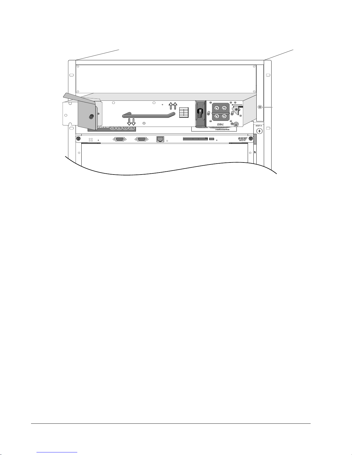
3Use the central handle to guide the power supply into the bay while supporting the supply
from the bottom with your other hand.
4Place both hands on each side of the power supply to slowly and evenly slide the power
supply into the bay. During the last inch of insertion into the chassis, place one hand on the
central handle to steady the power supply and use your other hand to gently push the
ejector/injector lever towards the power supply to engage the power supply backplane
connectors.
Caution: Do not slam the power supply into the backplane. This or other excessive force
will cause damage and possibly require the return of the chassis.
5Secure the power supply by tightening the screw on the ejector/injector lever using a #2
Phillips-head screwdriver.
6Slide the locking latch away from the remove position.
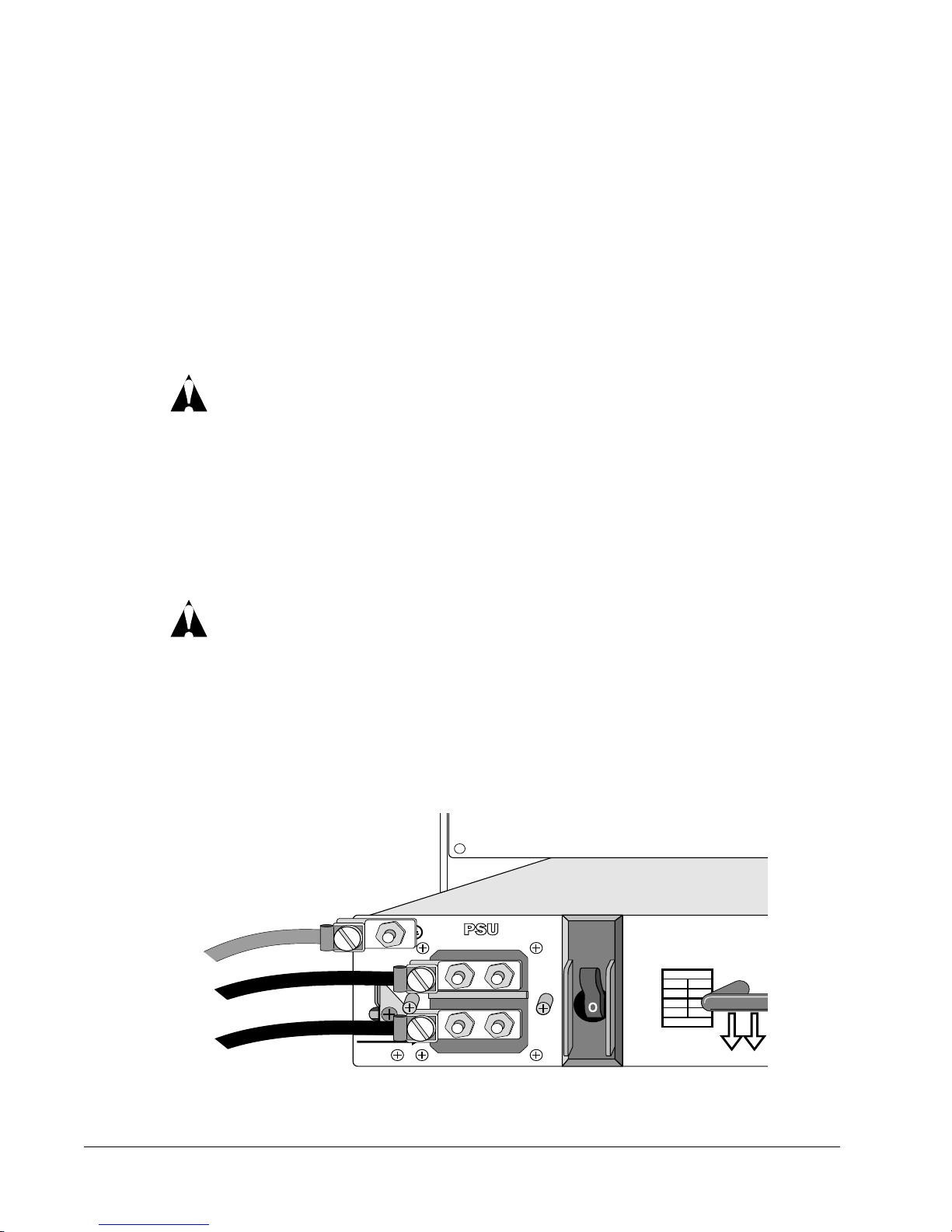
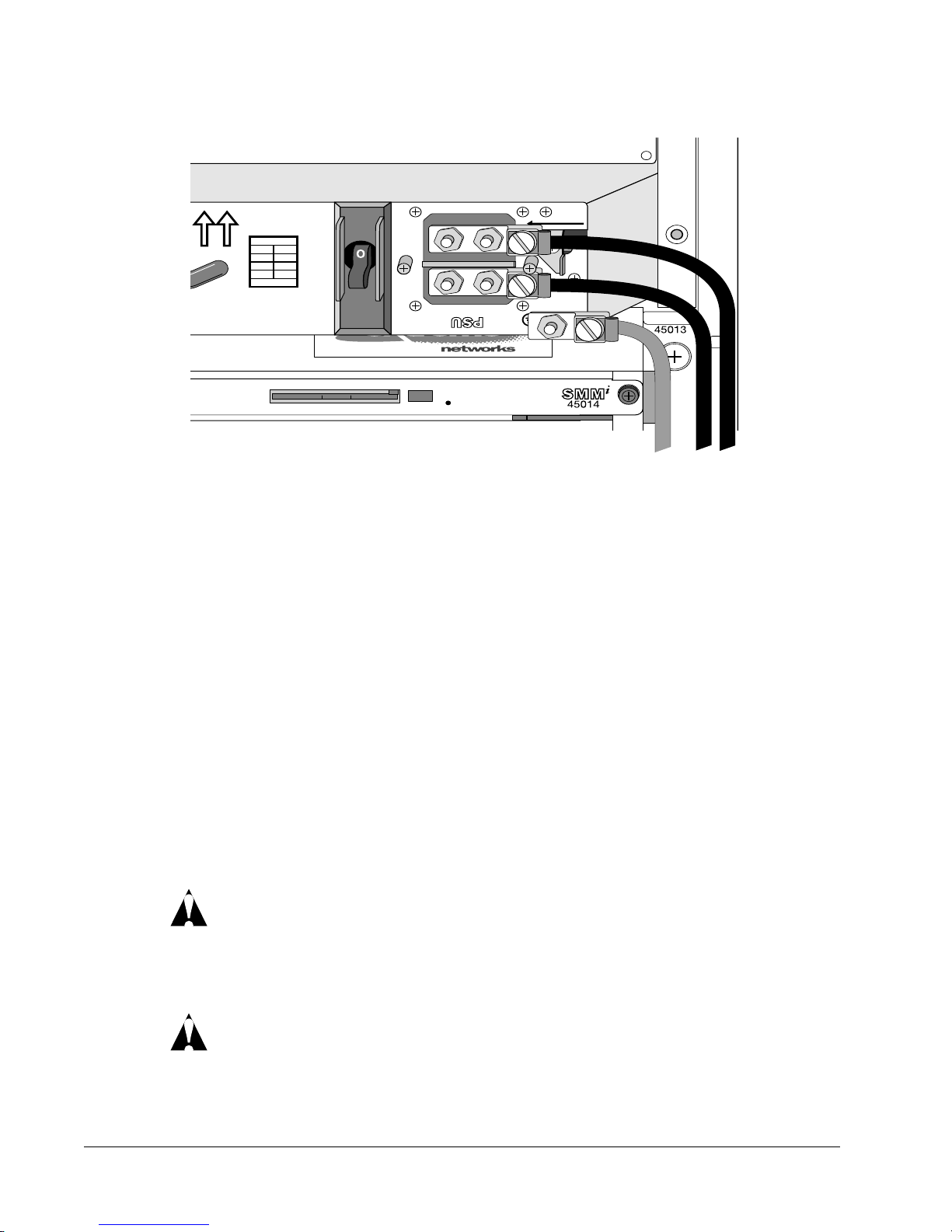
7Remove the plexiglas cover that shields the power connection on the power supply.
8Attach the DC power and ground cables to the power supply, as shown in Figure 4.