8. Use the Camera End Beam from
the hard case and slide it over the ex-
pansion joint.
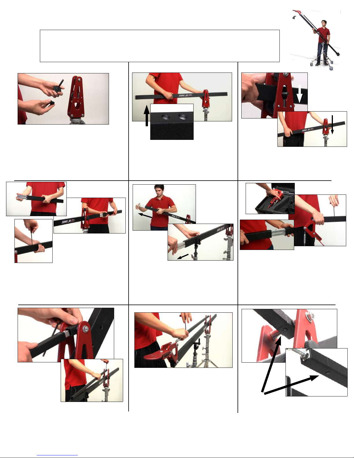
Use the T Handles Hex tool to expand
the joint and create a firm connection.
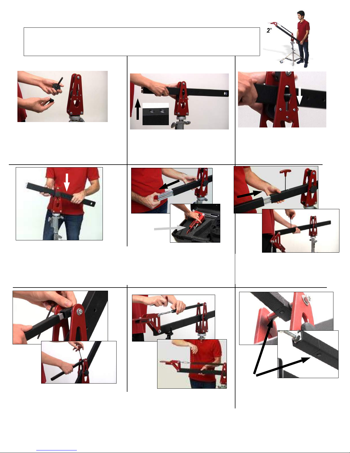
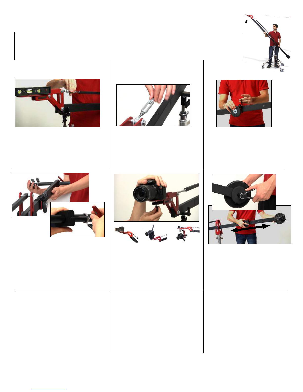
11. Merge the two pieces by running
the Center Pivot Bolt. Use the wide slot
space for easy bolt alignment. Slide if
down the slot and re attach the knob.
7. Pull out the expansion joint from the
end of the Center Jib Beam until the
spring pin clicks into place.
NOTE: You may want to use the
Steady Rest and stand to support the
Jib beam during set up.
9. Connect the male end of the 4 Para
Beam to the center post. Use the Hex tool
to screw the para beam set screw and se-
cure it into place.
6. Pull the expansion joint from the 2’ Tail
Beam until the spring pin clicks into place..
Insert it into the female end of the Center
Jib Beam. Use the hex tool to expand the
joint and secure the connection.
PIC/ VID
3. Remove the Center Pivot bolt from
the center post by unscrewing the soft
grip knob on the end.
4. Place the 4’ Tail Beam (w logo)
thru the hallow middle of the center
post. Position it so that the holes on
the beam’s edge are facing upward.
Vid Remove the Center Pivot
bolt from the center post.
PIC/ VID
PIC/ VID
5. Run the Center Pivot Bolt through
the Beam to the other side of the Center
Post. Use the wide space for easy bolt
alignment.
10. Connect the Turnbuckle on the
Camera Platform beam to the female
end of the Para Beam using the Hex
tool and set screw.
NOTE: Be sure the tip of the set
screw goes thru the bottom hole of the
Para Beam to form a secure connec-
tion. You should feel it protrude thru
the bottom of the beam.
Be sure to check this on both ends of
the para beam.
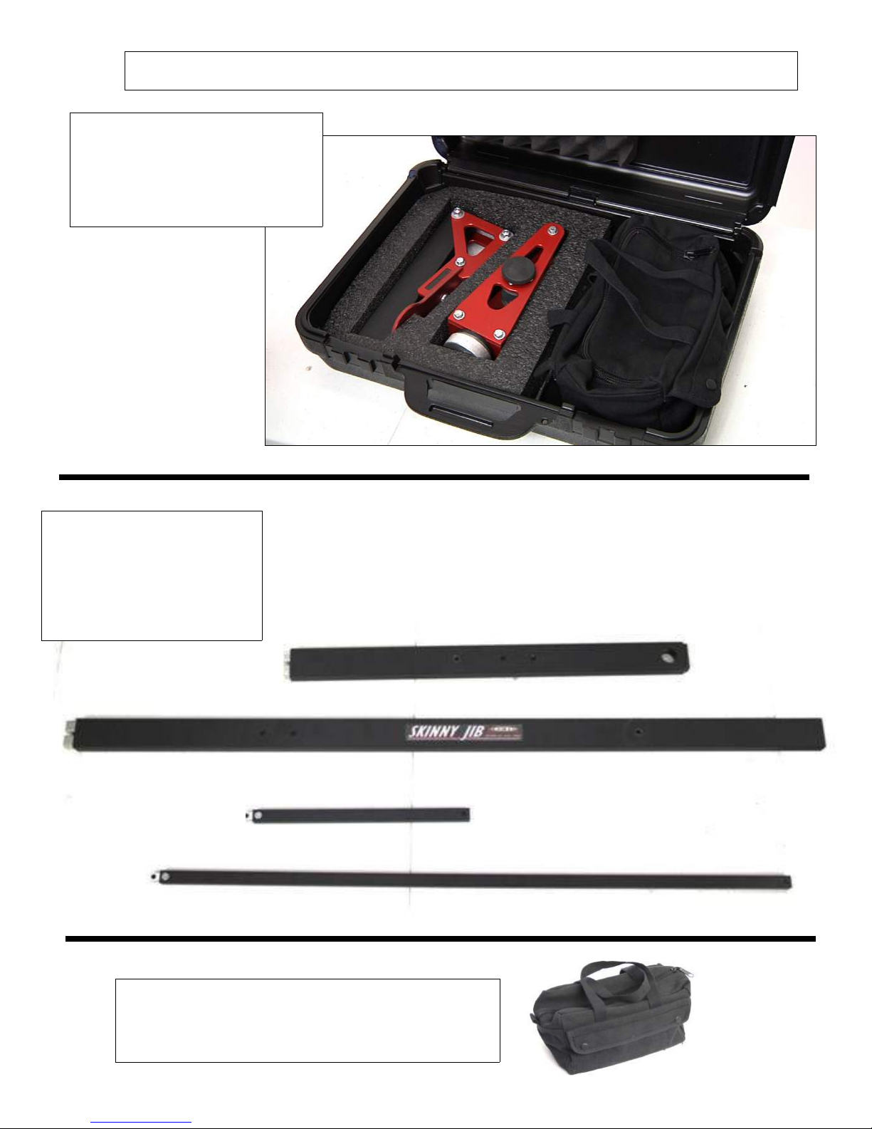
Skinny Jib SETUP INSTRUCTIONS - 4’ Configuration
STOP/ NOTE: The Skinny Jib can be used at 2’ or 4’ Configuration.
Below are the instructions for the 4’ Configuration. (Pages 8, 9 & 10)
Refer to pages 5, 6 and 7 for instructions on the 2’ configuration