manuals.online logo
Brands
  1. Home
  2. •
  3. Brands
  4. •
  5. Ezgo
  6. •
  7. Offroad Vehicle
  8. •
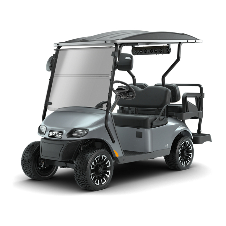
  9. Ezgo TXT 48V User manual

Ezgo TXT 48V User manual

REPAIR AND SERVICE MANUAL
TXT 48V
ISSUED JANUARY 2010
ELECTRIC POWERED GOLF CAR
614279
Page F-2
FRONT SUSPENSION AND STEERING
Repair and Service Manual
Read all of Section B and this section before attempting any procedure. Pay particular attention to all Notices, Cautions, Dangers and Warnings.
MAINTENANCE
In the following text, there are references to removing/installing
bolts etc. Additional hardware (nuts, washers etc.) that is
removed must always be installed in its original position unless
otherwise specified. Non-specified torque specifications are as
shown in the table contained in Section A.
Routine maintenance of the front suspension and steer-
ing consists of:
• periodic inspections for loose, worn or damaged
components
• alignment checks
• lubrication of ball joints and wheel bearings
See Lubrication Chart and Periodic Service Schedule in
Section A. Be sure to use only the recommended lubri-
cants. Maintain the correct adjustment of the front bear-
ings and repack them in accordance with the Periodic
Service Schedule or if a bearing replacement is
required. Routine examination of the tires will provide
indications if an alignment is required.
Lubrication
Tool List Qty. Required
Grease gun..................................................................1
Shop towels..............................................................AR
Grease the rack ball joint (1) and tie rod ends (2 and 3)
(Ref. Fig. 2 on Page F-2) per Periodic Service Schedule
in Section A. Wipe off old grease that is forced out of
rubber boot.
Fig. 2 Lubrication Points
Wheel Bearing and King Pin Bushing
Inspection
To prevent possible injury or death resulting
from a vehicle falling from a jack, follow the lift-
ing procedure in Section B of this manual. Be
sure the vehicle is on a firm and level surface.
Never get under a vehicle while it is supported
by a jack. Use jack stands and test the stability
of the vehicle on the stands before starting any
repair procedure. Always place chocks in front
and behind the wheels not being raised. Use
extreme care since the vehicle is extremely
unstable during the lifting process.
Lift the front of the vehicle and support on jack stands as
per SAFETY section. Rotate the front wheel and feel for
any roughness. While holding spindle with one hand,
grasp bottom of tire with other hand and rock tire back
and forth on spindle.
Some minor rocking movement of tire is normal.
If excess movement is detected, the wheel bearing may
require repacking and adjusting or replacement. “Wheel
Bearing Packing” on Page F-2 “Wheel Bearing Adjust-
ment” on Page F-3.
If the wheel bearing is satisfactory, a worn spindle bear-
ing, which is not a serviceable item, is indicated and the
spindle must be replaced. “Spindle Replacement” on
Page F-12
Wheel Bearing Packing
Tool List Qty. Required
Grease gun..................................................................1
Bearing packer (Recommended).................................1
Remove hub from spindle and disassemble. “Wheel
Bearing and Race Replacement” on Page F-8.
Clean all bearings, grease seal, hub and dust cap in sol-
vent and dry thoroughly. Inspect for signs of damage.
Pitting or a blue coloration of the rollers will require
replacement of the bearing. If the roller portion of the
bearing is to be replaced, the race must also be
replaced. “Wheel Bearing and Race Replacement” on
Page F-8.
The front wheel bearings are tapered roller type and
must be packed with grease at installation or any time
the bearing is removed for inspection. It is recom-
NOTICE
Front of Vehicle 1
3
2
NOTICE
FRONT SUSPENSION AND STEERING
Page F-3
Repair and Service Manual
Read all of Section B and this section before attempting any procedure. Pay particular attention to all Notices, Cautions, Dangers and Warnings.
mended that a bearing packer attached to a grease gun
be used; however, manual packing is acceptable if done
correctly. To pack a bearing manually requires that a dab
of grease be placed in the palm of the hand and the
bearing be dipped in the grease. Force the grease up
through and around all of the rollers until the entire bear-
ing is saturated in grease.
Assemble hub and install on spindle. “Hub Replace-
ment” on Page F-7.
Once hub is placed onto spindle and before outer wheel bear-
ing is installed, fill the area between the inner and outer wheel
bearings about 1/2 - 3/4 full with grease.
Wheel Bearing Adjustment
Tool List Qty. Required
Socket, 1 1/2", 1/2" drive.............................................1
Ratchet, 1/2" drive.......................................................1
Torque wrench, 1/2" drive, ft. lbs.................................1
Adapter, 3/8" drive to 1/2"............................................1
Torque wrench, 3/8" drive, in. lbs. ...............................1
If performing a wheel bearing adjustment only, lift and
support front of vehicle per SAFETY section. Remove
dust cap (1) and cotter pin (2) and loosen castellated nut
(3).
If performing a wheel bearing adjustment as part of
another procedure, make sure wheel is mounted to hub
hand tight with lug nuts (4) and hub is loosely retained
on spindle (5) with castellated nut (Ref. Fig. 3 on Page
F-3).
Seat bearings by rotating wheel while tightening castel-
lated nut until slight resistance is felt.
Rotate the wheel 2 - 3 more turns to displace excess
grease. If required, tighten castellated nut (3) again until
slight resistance is felt. If the cotter pin hole in the spin-
dle (5) aligns with a slot in the castellated nut, insert a
new cotter pin (2). If the hole does not align, the castel-
lated nut must be loosened to align with the closest
available slot in the nut.
Check for smooth and free rotation of the wheel and an
absence of play when the wheel is grasped by the out-
side of the tire. Bend the cotter pin (2) against the flats
of the castellated nut (3).
Replace the dust cap (1) and lower vehicle per SAFETY
section.
Fig. 3 Bearing Adjustment
If completing a wheel bearing adjustment as part of
another procedure, tighten front wheels per WHEELS
AND TIRES section.
Wheel Alignment
Tool List Qty. Required
Tape measure..............................................................1
Chalk............................................................................1
Wrench, 9/16"..............................................................1
Wrench, 3/4"................................................................1
Crowfoot socket, 3/4", 1/2" drive..................................1
Torque wrench, 1/2" drive, ft. lbs..................................1
Socket, 13 mm, 3/8" drive............................................1
Ratchet, 3/8" drive .......................................................1
Torque wrench, 3/8" drive, in. lbs.................................1
Lift the front of the vehicle and support on jack stands as
per SAFETY section. Confirm the alignment of the front
springs. “Front Spring Replacement” on Page F-6.
Rotate each wheel and scribe a chalk line around the
circumference of the tire at the center of the tread pat-
tern. Lower vehicle and, with tires in the straight ahead
position, roll it forward approximately five feet in order to
allow the tires to take their normal running position.
Measure the distance between the chalk lines at both
the front and rear of the tires (Ref. Fig. 4 on Page F-4).
The measurement taken at the front of the tires should
be 0" - 1/8" (0 - 3 mm) less than the rear.
NOTICE
Front of Vehicle
3
1
2
4
5
Page F-4
FRONT SUSPENSION AND STEERING
Repair and Service Manual
Read all of Section B and this section before attempting any procedure. Pay particular attention to all Notices, Cautions, Dangers and Warnings.
Fig. 4 Wheel Alignment
To hold threaded tube while loosening jam nut, use a
wrench on the center, flat section of tube.
The tie rod has different threads on each end. The end with
the groove in the threaded tube has left hand threads while
the end without the groove has conventional right hand
threads.
To adjust wheel alignment, loosen tie rod jam nuts (1)
and turn tie rod (2) until correct alignment is achieved.
Tighten jam nuts to 36 - 40 ft. lbs. (49 - 54 Nm) torque.
Test drive vehicle and confirm steering wheel is cor-
rectly centered. If it is not centered, disconnect interme-
diate shaft from steering shaft and center steering
wheel (Ref. Fig. 5 on Page F-4). Reconnect intermedi-
ate shaft and tighten bolt to 155 - 215 in. lbs. (180 - 250
kg cm) torque.
Fig. 5 Disconnect Intermediate Shaft to Center
Steering Wheel
X
Rear
X
Front
1/8" (3 mm)
0" (0 mm)
-
+
21
1
View from Underside
of Vehicle
Front of Vehicle
NOTICE
Intermediate
Shaft
Remove Bolt

Other Ezgo Offroad Vehicle manuals

Ezgo TXT 48V User manual

Ezgo

Ezgo TXT 48V User manual

Ezgo 602080 User manual

Ezgo

Ezgo 602080 User manual

Ezgo EZGO User manual

Ezgo

Ezgo EZGO User manual

Ezgo RXV FREEDOM User manual

Ezgo

Ezgo RXV FREEDOM User manual

Ezgo RXV ELECTRIC User manual

Ezgo

Ezgo RXV ELECTRIC User manual

Ezgo FREEDOM Instruction Manual

Ezgo

Ezgo FREEDOM Instruction Manual

Ezgo 2Five User manual

Ezgo

Ezgo 2Five User manual

Ezgo 622021-GB User manual

Ezgo

Ezgo 622021-GB User manual

Ezgo TXT FLEET User manual

Ezgo

Ezgo TXT FLEET User manual

Ezgo SHUTTLE 4 User manual

Ezgo

Ezgo SHUTTLE 4 User manual

Ezgo 622021-FI User manual

Ezgo

Ezgo 622021-FI User manual

Ezgo RXV golf car 2008 User manual

Ezgo

Ezgo RXV golf car 2008 User manual

Ezgo 605681 User manual

Ezgo

Ezgo 605681 User manual

Ezgo EZGO 2001 User manual

Ezgo

Ezgo EZGO 2001 User manual

Ezgo 2010 TXT 48 FLEET User manual

Ezgo

Ezgo 2010 TXT 48 FLEET User manual

Ezgo 611103 Operating instructions

Ezgo

Ezgo 611103 Operating instructions

Ezgo 28645-G01-DK Instruction Manual

Ezgo

Ezgo 28645-G01-DK Instruction Manual

Ezgo FREEDOM User manual

Ezgo

Ezgo FREEDOM User manual

Ezgo EZGO User manual

Ezgo

Ezgo EZGO User manual

Ezgo TERRAIN 1000 User manual

Ezgo

Ezgo TERRAIN 1000 User manual

Ezgo FREEDOM HP User manual

Ezgo

Ezgo FREEDOM HP User manual

Ezgo RXV GOLF CAR User manual

Ezgo

Ezgo RXV GOLF CAR User manual

Ezgo TXT Fleet Electric User manual

Ezgo

Ezgo TXT Fleet Electric User manual

Ezgo 605681 User manual

Ezgo

Ezgo 605681 User manual

Popular Offroad Vehicle manuals by other brands

Yamaha SRX700D Service manual

Yamaha

Yamaha SRX700D Service manual

Polaris 2011 PREDATOR 50 Service manual

Polaris

Polaris 2011 PREDATOR 50 Service manual

GAS GAS K2 QUAD 250 - SERVICE Service manual

GAS GAS

GAS GAS K2 QUAD 250 - SERVICE Service manual

Polaris Sportsman 500 H.O. owner's manual

Polaris

Polaris Sportsman 500 H.O. owner's manual

GMX GMXK150WHI Assembly manual

GMX

GMX GMXK150WHI Assembly manual

Textron PROWLER 500 2018 Operator's manual

Textron

Textron PROWLER 500 2018 Operator's manual

Yamaha YFM250RX 2008 Service manual

Yamaha

Yamaha YFM250RX 2008 Service manual

Yamaha KODIAK 400 Ultramatic 4x4 owner's manual

Yamaha

Yamaha KODIAK 400 Ultramatic 4x4 owner's manual

Yamaha GRIZZLY 350 owner's manual

Yamaha

Yamaha GRIZZLY 350 owner's manual

Yamaha BLASTER YFS200V owner's manual

Yamaha

Yamaha BLASTER YFS200V owner's manual

Arctic Cat 450 i TRV/OT Operator's manual

Arctic Cat

Arctic Cat 450 i TRV/OT Operator's manual

Crossfire 500ATV owner's manual

Crossfire

Crossfire 500ATV owner's manual

Segway SGW500F-A7 owner's manual

Segway

Segway SGW500F-A7 owner's manual

A-EON Cobra 220 Service manual

A-EON

A-EON Cobra 220 Service manual

cectek Gladiator Service manual

cectek

cectek Gladiator Service manual

KYMCO Mongoose 90 R owner's manual

KYMCO

KYMCO Mongoose 90 R owner's manual

Yamaha VIKING YXM700PE owner's manual

Yamaha

Yamaha VIKING YXM700PE owner's manual

Can-Am 2007 Mini DS90 Operator's guide

Can-Am

Can-Am 2007 Mini DS90 Operator's guide

manuals.online logo
manuals.online logoBrands
  • About & Mission
  • Contact us
  • Privacy Policy
  • Terms and Conditions

Copyright 2025 Manuals.Online. All Rights Reserved.