eZway EZ 900HC Specifications

Form 2-202
Rev. 7/31/18
EZ 900
Bathtubs
Operator’s Instructions
EZ Way, Inc.
PO Box 89
Clarinda, IA 51632
1-800-627-8940
www.ezlifts.com
WARNING: Cancer and Reproductive Harm - www.P65Warnings.ca.gov.

Study this manual carefully before operating your bathing system.
This bath system is intended for professional use only where the patient is under supervision of trained personnel.
Operating instructions and recommended maintenance procedures are explained in the following pages. If you
have any questions regarding the operation or maintenance of your bathing system and cannot find the answer in
this manual, please contact us at 1-800-627-8940.
The system is designed for years of trouble-free operation, with proper use and maintenance. Bathtub and shower
water must be run at least every three days.
Height Adjustable Models
EZ 900H
EZ 900HC cleaning
EZ 900HCW cleaning/whirlpool
Fixed Height Models
EZ 900F
EZ 900FC cleaning
EZ 900FCW cleaning/whirlpool
2

3
Unpacking Instructions
Unpack the EZ 900 Height Adjustable Bathtub panel by removing the screws (A) on both sides of the pallet and
remove the crate.
Assemble the bathtub (cardboard box) to the panel by removing the back of the panel, and use the transport
wheel beam (B) and wooden ramp L=4’1” (C), if ordered, to unload off pallet. The transport wheel beam can
also be used to transport the bathtub in place into the bathroom.
EZ Way recommends using at least two people when handling and transporting the tub.
Measurements: 5’ x 3’2” x 4’4” (L x W x H). Gross weight: 500 lbs.
A
C B

Features and Controls
Bathtub Height Adjustment and Filling
Position Description
1. Bathtub up/down control buttons
2. Thermoscopic mixer
3. Thermometer
4. On-off valve for bathtub filling
5. Bathtub filling spout
6. Bathtub overflow drain
Drain-close/open
Patient Shower
Position Description
2. Thermoscopic mixer
3. Thermometer
9. On-off valve for patient showering
10. Patient shower hose
11. Patient shower handle
12. Handle bracket
Cleaning System (C)
Position Description
13. Shut-off safety valve
14. Spray equipment hose
15. Spray handle
16. Spray handle bracket
17. Mixing setting screw (inside the panel)
18. Detergent filling lid
19. Yellow cleaning adapter, for whirlpool
Whirlpool System (W)
Position Description
20. Motor control on/off for whirlpool
21. Adjustable whirlpool jet
22. Aeration control valve
23. Whirlpool inlet safety screen
24. Adjustable footrest, two positions
16
17
14
13
18,19
15
4

5
Autofill Controls
Bathtub Filling
Start the automatic bathtub filling process by
pressing the “bathtub filling symbol” (4) to the left
of the thermostat (2). The green light (30) will be
lit and water will fill the bathtub.
The red “running water” light (31) to the right of
the thermometer indicates that the thermometer
shows the filling water temperature and can be
adjusted by turning the thermostat knob (2).
When the water level reaches the “waterline” inside
the bathtub, (about 53 gallons, 200 liters) the
bathtub filling will automatically stop and both the
green (30) and the red light (31) will switch off.
The light (33) automatically indicates that
the thermometer shows the still bathtub water
temperature.
More water can be added into the bathtub. When
pressing the “bathtub filling symbol” (4) once more,
the green light (30) will flash and water will be
added for approximately one minute.
This procedure can be repeated or stopped by
pressing the “bathtub filling symbol” (4).
WARNING: Always physically check water
temperature before and during bathing/showering
to ensure that the thermoscopic mixer (2) is
functioning.
Showering
Remove the shower handle (11) from the panel and
hold it over the bathtub away from the patient.
Press the “shower handle symbol” (9) to the right of
the thermostat. The green light (32) will illuminate
and water will spray from the shower handle.
The red “running water” light (31) to the right of
the thermometer indicates that the thermometer
shows the running shower water temperature and
can be adjusted by turning the thermostat knob.
Stop the water flow by pressing the “shower handle
symbol” (9) once. Both the green (32) and the red
(31) lights will switch off. The procedure can be
repeated.
The shower water flow is preset when installing the
bathtub. If other shower flows are required, set the
water flow by adjusting the black ball valve inside
the panel.
Whirlpool
To start the whirlpool system, press the whirlpool
symbol (20) and the green light (34) will be lit.
To stop the whirlpool system, press the whirlpool
symbol (20) and the green light (34) will switch off.
Important: Never start the whirlpool when the
water level is below the jet (21). Read separate
whirlpool instructions.

Basic Operating Procedures
Use the following controls for filling tub and
showering patients. The Whirlpool and cleaning
system are described separately.
Controls
The 900 Bathing System control panel and bathtub
are made of fiberglass. It has a thermoscopic mixer
(2) for the bathtub filling and the patient shower.
The thermoscopic mixer regulates water valve
temperature for the bathtub fill and the patient
shower.
To calibrate the thermoscopic mixer, see enclosed
product manual.
In addition, there are shut-off valves for the tub fill
(4) and patient shower (9).
The thermometer (3) measures bathtub filling water
and patient shower temperature in C.
The temperature probe is located close to the
thermoscopic mixer (2) to provide an accurate
reading of water temperature as the bathtub fills.
By monitoring the thermometer, you can precisely
regulate water temperature with use of the
thermoscopic mixer (2) as the tub fills or when the
patient shower (11) is used.
Height of the tub is adjusted with the tub up/down
controls (1). The tub can be adjusted to any level
from 600 mm (24”) to 1000 mm (40”) above the
floor.
To lower the tub, press and hold the down button
(1). To raise the tub, press and hold the up button
(1).
When releasing the up or down buttons, the
bathtub stops in desired height position.
6

7
Shower System Operation
The patient shower includes a handle (11) located
on the right side on the panel, the thermoscopic
mixer (2) and a shut-off valve (9) on the front of
the control panel. The handle nozzle has a rubber
strainer which is easy to clean, just rub your thumb
over the strainer.
Using the Shower
1. Lift the shower handle (11) and hold it over the
tub, away from patient.
2. Turn valve (9) to “ON” position for patient
shower.
3. Set the thermoscopic mixer (2) to desired
temperature.
4. Physically test water temperature and adjust
thermoscopic mixer (2) to suit. Adjust water
flow with shutoff valve (9) located on front of
control panel.
5. Shower or rinse patient with shower handle.
6. After showering, turn valve (9) to “OFF”
position and return handle (11) to its bracket
(12).
The patient shower system is also useful for rinsing
residue and debris from tub when cleaning (see
cleaning system description).
Please note: Shower handle should not be held in
the bath water while bathing.
Whirlpool
The shower hose shall be used when flushing the
whirlpool system, see separate description.

Whirlpool System Operation
The EZ whirlpool system allows you to regulate
both water flow directions and quantity of air.
Using the Whirlpool System
1. Turn the adjustable whirlpool outlet jet (21),
located at the drain end of the tub, counter-
clockwise to completely open position.
2. Fill the bathtub making sure that the water
level covers the outlet jet (21). Also, ensure
that the whirlpool inlet screen (23) is in place.
WARNING: Always physically check water
temperature before and during bathing/
showering to ensure that the thermoscopic
mixer is functioning.
3. Set the adjustable whirlpool outlet jet (21) for
desired flow direction. Centred for the perineal
area or to either side for circular flow. The
adjustable jet rotates in a friction housing and
is easily turned to the desired position. Avoid
placing the jet in a full upward position, as this
could cause the water to splash.
4. With the patient in the bathtub, turn on the
whirlpool unit by pushing the “ON-OFF”
control button (20) on the control panel. Make
sure the whirlpool inlet screen (23) is not
obstructed so that full flow is maintained.
5. To make any further adjustments in water flow
direction, change the adjustable whirlpool
outlet jet (21).
6. Increase or decrease whirlpool stream by turning
the air control (22).
7. Turn the whirlpool unit off by pushing the
“ON-OFF” control button (20) on the control
panel.
Please note: If the whirlpool motor starts without
any jet stream in the bathtub, verify that the
adjustable whirlpool outlet jet (21) located at the
drain end of the tub is fully open. If not, turn it
counter-clockwise to completely open position.
Verify that the screen (23) is in place. Do not start
the pump if the screen is missing.
WARNING: Disconnect electric power before
attempting any service or repair.
8

9
Patient Handling
Preparing Tub for Use
1. Close the drain plug by turning the overflow
drainage knob (6).
2. Set adjustable foot rest (8) into position
appropriate for the patient’s legs.
3. Fill tub using on-off valve (4).
4. Set and monitor fill water temperature with
thermoscopic mixer (2) and thermometer (3).
Please note: Footrest is not used when patients are
transferred into the tub on EZ Way’s stretcher lift.
WARNING: Always physically check water
temperature before and during bathing/showering
to ensure that the thermoscopic mixer (2) is
functioning.
Ambulatory Patient Transfer
For patient comfort and safety, we recommend that
ambulatory patients are transferred directly into the
prefilled tub on EZ Way’s stretcher/chair lift.
Refer to the Mobile Bath Lift System operating
manual for correct procedures. See page 10 of
this manual for “Patient Transfer into Tub” for
recommended procedures for bathing patients on
the chair lift and stretcher lift.
Ambulatory patients can step into the tub, in its
lowest position, with assistance. When patient is
comfortable, raise tub with the tub lift control (1)
on the panel to a comfortable working height.
After use, lower the tub to allow the patient to exit.

manual.
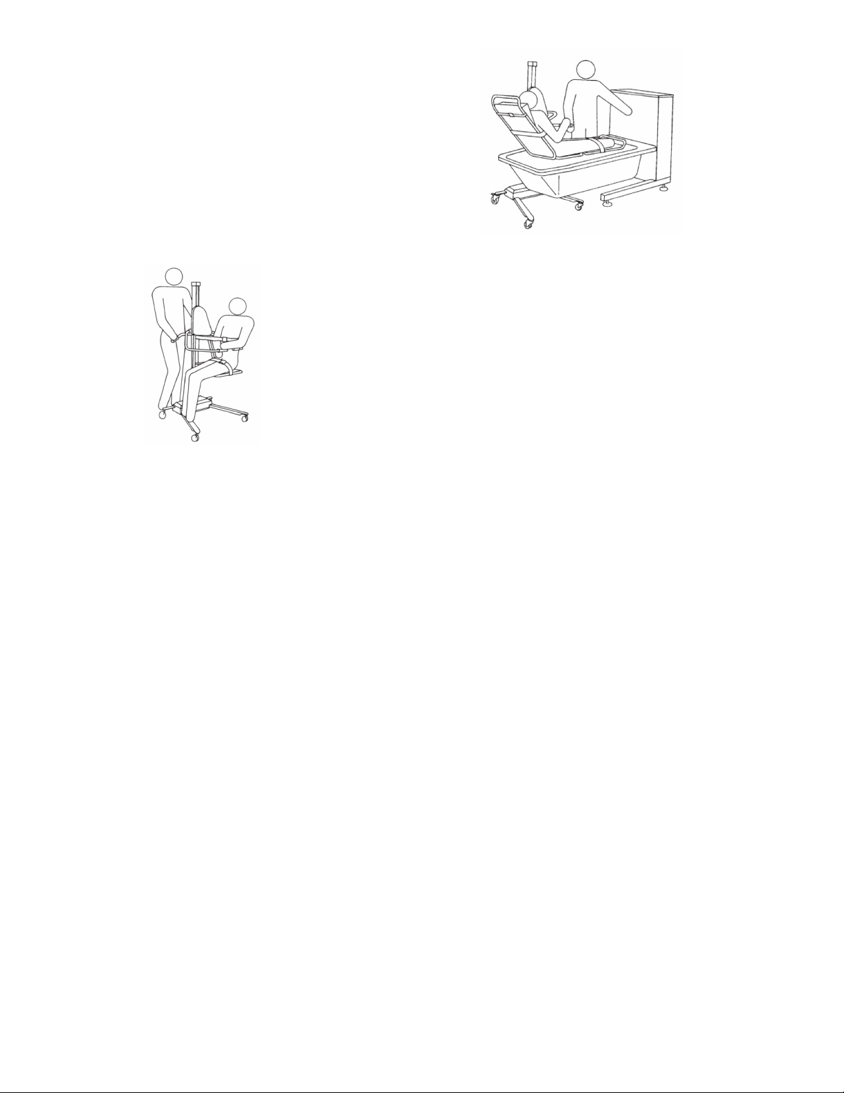
Recumbent Patient Transfer, EZ Way Stretcher Lift
Recumbent patients can be transferred directly and
safely into the tub, on the height-adjustable EZ
Way stretcher lift. Refer to the EZ Mobile Bath Lift
System operator’s manual for correct procedure.
Transferring Patient on Stretcher Lift into Tub
1. Prefill the tub in its lowest position and
physically test water for proper temperature.
Move patient on the stretcher lift over tub
and lock the lift casters. Important: Raise the
stretcher to ensure clearance over the rim of
the tub. This is to avoid the patient from being
pinched between tub rim and stretcher frame
during transfer. The footrest in the tub is not
used together with the stretcher.
2. Raise the tub to a comfortable working height.
When the tub is in position, you can lower the
stretcher into the tub using the lift. Important:
Before raising or lowering the tub, make
sure that the patient’s hands firmly grasp the
stabilizing bar on stretcher or that the patient’s
arms are crossed over his/her body. This is to
avoid pinching arms or fingers between the
stretcher frame and tub rim when the stretcher
is lowered or raised.
3. After bathing, lower the tub to raise the patient
above the water level to allow water to drip into
the tub. You can use the patient shower system
to rinse the patient in this position. The patient
can then be dried or wrapped in a bath towel
and transferred away from the bathtub.
Please note: Wipe beneath stretcher to prevent
water from dripping on the floor.
Important: Safety belts must be securely fastened
around patient at all times. For further details,
refer to the EZ Mobile Bath Lift System operator’s
manual.
Patient Handling
Patient Transfer into Tub with EZ Mobile Bath
Lift System
While sitting, safely secured patients can be
transferred directly into the tub on the height-
adjustable EZ Mobile Bath Lift System. Refer to the
EZ Mobile Bath Lift System operator’s manual for
correct procedures.
Transferring Patient on Mobile Bath Lift System
into Tub
1. Prefill the tub in its lowest position and
physically test water for proper temperature.
Move patient on the chair into position over
tub and lock the chair lift casters.
The adjustable footrest in the tub can be used
together with the chair to add patient comfort
and security. Important: Raise chair seat to
ensure clearance of all body parts over the tub
rim. This is to avoid the patient from being
pinched between tub rim and chair frame
during transfer.
2. Raise the tub to a comfortable working height.
When the tub is in place, lower the chair into
the tub. For added patient comfort, arm support
and backrest can be rotated to outer side of tub
rim. Important: Make sure that the patient’s
arms are crossed over his/her body. This to avoid
pinching arms or fingers between chair frame
and tub rim when chair is lowered or raised.
3. After bathing, lower the tub to raise the patient
above water level to allow water to drip into the
tub. You can use the patient shower system to
rinse the patient in this position. The patient
can then be dried or wrapped in a bath towel
and transferred away from the bathtub.
Please note: Wipe beneath chair to prevent water
from dripping on the floor.
Important: Safety belts must be securely fastened
around patient at all times. For further details,
refer to the EZ Mobile Bath Lift System operator’s
10

11
Cleaning System Operation
Important: This system is never to be used on
patients, only on equipment.
The cleaning detergent is mixed with cold water to
minimize inhalation.
The cleaning spray handle (15) on the yellow hose
is located on the side of the control panel in a
bracket (16).
Water flow is controlled by a shut-off safety valve
(13) with a key, located on the left end wall of the
control panel.
Detergent is automatically mixed with the water,
in a pre-set concentration of approximately 2%,
controlled by a mixing setting screw (17) on the
injector inside the panel. When an alternative
calibration setting is required, see next column.
Daily Use of the Cleaning System:
1. Remove the cleaning spray handle (15) from
bracket (16). Hold the handle over the bathtub
while opening the shut-off safety valve (13)
with the special key.
2. Briefly spray the cleaning mixture into the tub
while checking the color, smell and the foam of
the mixture. Spray over all interior surfaces of
the tub. Remove residue and debris with cloth
or brush.
3. To clean the EZ chair lift and stretcher lift,
position them over the tub and spray them
with cleaning mixture. The chair and stretcher
have removable pads and the stretcher has a
head pillow that can be placed in the tub for
cleaning.
4. After cleaning, rinse with fresh water using the
shower handle on the right side of the control
panel.
Detergent Filling
Open the lid (18) on top of the panel and fill with
maximum 4-1/3 cups (1.5 liter) of concentrated
detergent.
WARNING: Avoid skin or eye contact with
cleaning/detergent, which can be highly corrosive.
If contact is made, rinse immediately with excess
water. If irritation occurs, consult a doctor.
Always read and follow detergent supplier
directions carefully.
Calibrating the Detergent Mixture of the Cleaning
System
Detergent is automatically mixed with the cold
water, in a pre-set mixture of 2% at the factory.
If an alternative calibration is needed, follow the
instructions below to achieve a mixture of 2% or
what is recommended by your detergent supplier.
To calibrate the mixing setting, you will need:
• Screwdriver
• Measuring cup of at least 10 ounces
• Bucket with at least 3-gallon capacity
A. Remove the back panel cover.
B. Empty the detergent bottle by loosening its hose
from the injector. When empty, connect the
hose to the injector again.
C. Fill the measuring cup with 8 ounces of
concentrated detergent, open the detergent
bottle lid (18) and pour it into the bottle.
D. Place the empty 3-gallon bucket in the tub and
hold the cleaning spray handle (15) with yellow
hose over the bucket for filling.
E. Open the cleaning key-grip safety valve (13)
to completely open position and spray into the
bucket.
F. Observe the water level when bucket fills while
the bottle empties. Bucket should reach the
3-gallon mark at the same time as the bottle
empties. If bucket fills first, turn the detergent
mixing setting screw (17) on the injector
slightly counter-clockwise, using the screwdriver.
If bottle empties first, turn the detergent mixing
setting screw (17) slightly clockwise.
16
17
14
13
18,19
15

G. Repeat procedures A-F until the mixture is as
required.
H. Close cleaning key-grip safety valve (13), and
return the cleaning handle (15) to the bracket
(16) on the side of the panel.
I. Attach the back panel cover.
The cleaning system is now ready for use. See
detergent filling on previous page.
Once the proper mixture setting is established, no
further calibration is required unless a different
detergent is used.
Please note: Mixture should be calibrated in
accordance with your detergent supplier.
Whirlpool System Cleaning
Clean the Whirlpool System
A tailor-made yellow whirlpool inlet cleaning
adapter (19) for the whirlpool system is delivered
separately with the EZ 900 HCW. It is to be stored
on top of the detergent filling lid (18).
1. Turn the adjustable whirlpool outlet jet (21)
located at the drain end of the tub counter-
clockwise to completely open position.
2. Remove the whirlpool inlet safety screen (23)
by turning the screen counter-clockwise.
3. Fit in the yellow adapter (19) placed on top of
the detergent filling lid (18) to the whirlpool
inlet (24).
4. Remove cleaning shower handle (15) from
yellow cleaning hose (14) by pressing the dots
on the quick coupling.
5. Snap the hose with its coupling onto the
adapter and flush cleaning through the system
by turning the cleaning “key” (13) on the side
of the panel.
6. Cleaning mixture will flush through the
whirlpool outlet (21) into the tub.
7. When this is done, turn cleaning system off and
repeat procedure with patient shower handle
(11) to flush system with fresh water.
8. Return the yellow adapter (19) onto the top of
the detergent filling lid (18).
Safety and Control Instructions
• Ensure that the bottle is filled with detergent, see
previous page.
• Never use cleaning shower handle on patients as
detergent is highly corrosive. The hose is placed
opposite the patient shower to prevent misuse.
• Equipment must be cleaned after each use.
WARNING: Avoid skin or eye contact with
detergent, which is highly corrosive. If contact
is made, rinse immediately with excess water. If
irritation occurs, consult a doctor. Always read
and follow detergent supplier instructions.
12
16
17
14
13
18,19
15

13
Cleaning the Adjustable Whirlpool Jet (21)
Cleaning the jet: Turn the “jet friction housing”
counter clockwise 90° and pull it out. Clean the jet
and the housing.
Cleaning the valve housing: Remove by lifting the
two hooks (inside the housing) and pull it out.
Cleaning the valve (inside): Turn it counter-
clockwise and pull out.
Cleaning the Screen (23)
Remove the whirlpool inlet safety screen by turning
it counter clockwise.
WARNING: Avoid shin or eye contact with
detergent, which is highly corrosive. If contact
is made, rinse immediately with excess water. If
irritation occurs, consult a medical doctor. Always
read and follow label directions carefully.
Routine Maintenance
Daily Maintenance
• Clean the tub after every use.
• Check the cleaning supply at least daily,
depending on the frequency of use.
• Avoid abrasive cleaners which may scratch the gel
coat finish of the fiberglass bathtub and the panel.
• When the tub is not in use, lower it to its lowest
position and make sure all valves are closed.
• Clean the strainers on the patient and cleaning
shower handles by rubbing it with your thumb.
• Visually inspect the tub interior to make sure
there are no nicks or cracks which may scratch the
patient.
Please note: Iodine, bromine, and methylene blue
can discolor the fiberglass.
The recommended frequency of these maintenance
procedures will depend on the hardness of your
water supply and how often the equipment is used. It
is good practice to establish these routine procedures
on a weekly basis and then adjust the frequency as
your conditions indicate.
All mechanical parts inside the bathtub panel are
maintenance free.
WARNING: The equipment must not be used
in any way that varies from the safety precautions
and operating procedures detailed in this manual.
The equipment must not be operated by anyone
until the user has read and understands the
operating manual.

Installation Instructions
Bathroom Layout
Recommended room size: 10’ x 11’, or larger.
EZ Way recommends at least two people assemble
the bathtub.
Plumbing Rough - In
• The EZ Way installation set includes check
valves, valve with strain, NPT20 nipples and
flexible hoses.
• All other pipes and fittings to and from bath
connections are to be supplied by others and
installed to comply with local building and
plumbing regulations.
• To eliminate pipe debris it is essential that supply
pipes are thoroughly flushed before connecting
the bathtub.
• Level the bathtub legs by adjusting the feet.
• Avoid any kinks on the hose curve when
connecting to the bathtub.
• The bathtub drainage shall be connected to floor
or wall drainage.
• The thermostat is preset at the factory. Read the
Rada 320 Series Product Manual when calibrating
the thermostat.
Electrical Rough-In
Standard electrical requirements: 110 volts, 60 Hz,
16 Amps.
Permanent connection installed by others.
Please note: All electrical conduit, fitting and
wire to bath is to be supplied and installed by your
professional electrician in accordance with local or
applicable electric code as a minimum requirement.
Main switch, in accordance with IEC 328, with
green signal lamp, 16 A main fuse and earth circuit
breaker are not included and must be separately
purchased.
TECHNICAL SPECIFICATIONS
Weight Filled: 1,100 lbs.
Weight Empty: 500 lbs.
Water Volume: 66 USG
Water Pressure:
40-85 psi.
Inlet dynamic pressures nominally balanced
to within 10% of each other during flow
Flow Rate: 2-32 USG
Hot Water Temperature: 150° F, recommended
Drainage: .45 USG per second
CAUTION: Polarity and grounding must be correct.
Improper connection may result in injury.
• Black 1 for Neutral/Common
• Black 2 for Line/Hot
• Yellow/green for ground
No serviceable parts are located inside of the
bathtub.
Environmental Conditions
• Ambient temperature range of +10° C to +40° C
• Relative humidity range of 30% to 75%
• Atmospheric pressure range of 700 hPa to 1060
hPa
14

15
Floor Drainage
Mount the bracket for the drainage pipe to the front
of the panel. Adjust by cutting the length of the
pipe.
Wall Drainage
Mount the bracket for the drainage pipe to the back
of the panel.

900 HCW Installation Drawing
3-1/2”
2-1/2”
WALL DRAINAGE
FLOOR DRAINAGE
MIN 10” 17-3/4”
1-1/2”
MIN 1’ 11-3/4” MAX 3’ 3-1/3”
MIN 3’ 7-3/4” MAX 4’ 11-1/2”
WALL
16

17
900 FCW Installation Drawing
3-1/2”
2-1/2”
WALL DRAINAGE
FLOOR DRAINAGE
MIN 10” 17-3/4”
1-1/2”
2’ 8”
4’ 4”
WALL

Installation Drawing
2’ 8-3/4”
1’ 7-1/2”
4”
8” 1’ 9-1/2”
2’ 3-1/3”
2’ 3/4”
2’ 3-1/2”
2’ 8-3/4”
7’ 7-1/2”
4” 3”
2’ 1-3/4”
1’ 9”
3-3/4”
8”
5-1/2” 6-1/4”
2”
18

19
Wiring Diagram

Wiring Diagram
20
This manual suits for next models
6
Table of contents
Other eZway Bathtub manuals
Popular Bathtub manuals by other brands

Whirlpool
Whirlpool Ariel ARL-702 installation manual

Kohler
Kohler K-1151 Homeowner's guide

American Standard
American Standard 3052OD.X0X Installation instructions and owner's manual

Kohler
Kohler K-1111-H2 Roughing-In Guide

Kohler
Kohler K-1158 Roughing-In Guide

Kohler
Kohler Hourglass K-1209-LA Roughing-In Guide