2
2
INDEX
SAFETY INFORMATION......................................................................................................................................................... 4
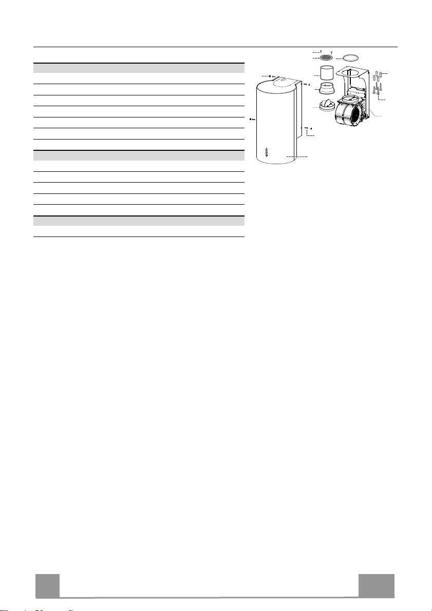
CHARACTERISTICS ............................................................................................................................................................. 7
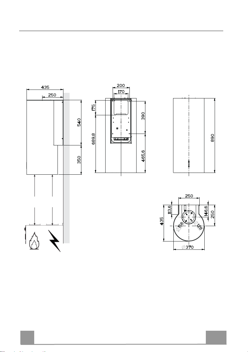
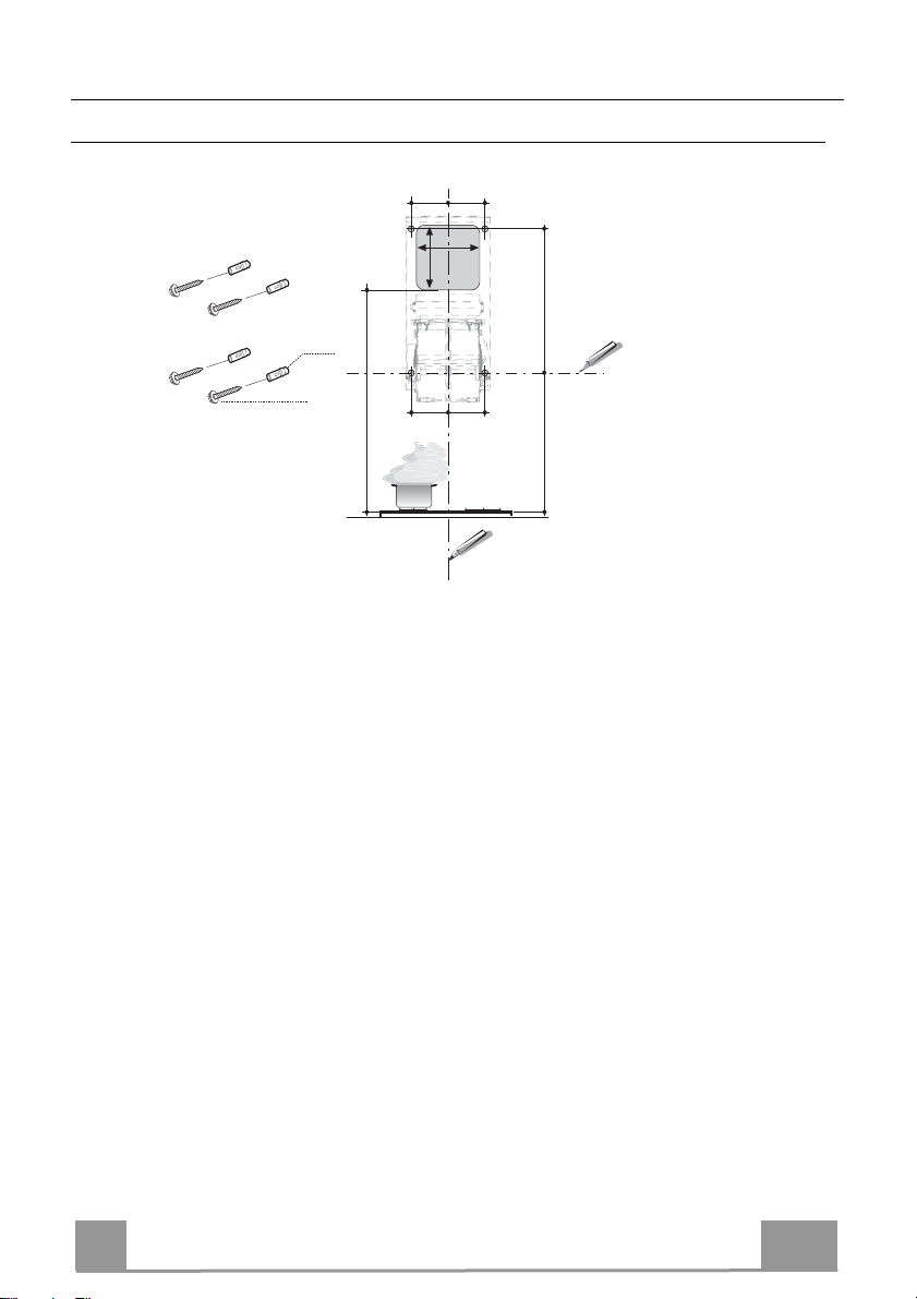
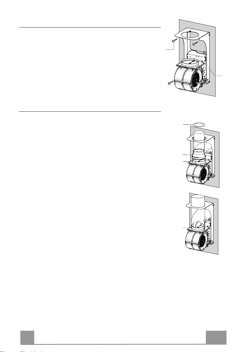
INSTALLATION...................................................................................................................................................................... 9
USE ...................................................................................................................................................................................... 13
MAINTENANCE................................................................................................................................................................... 14
УКАЗАТЕЛЬ
ИНФОРМАЦИЯ ПО БЕЗОПАСНОСТИ................................................................................................................................ 16
ХАРАКТЕРИСТИКИ............................................................................................................................................................ 19
УСТАНОВКА........................................................................................................................................................................ 21
ЭКСПЛУАТАЦИЯ................................................................................................................................................................ 25
УХОД.................................................................................................................................................................................... 26
INDHOLD
OPLYSNINGER OM SIKKERHED......................................................................................................................................... 28
APPARATBESKRIVELSE ................................................................................................................................................... 31
INSTALLATION.................................................................................................................................................................... 33
BRUG................................................................................................................................................................................... 37
VEDLIGEHOLDELSE .......................................................................................................................................................... 38
ÍNDICE
INFORMACIÓN DE SEGURIDAD.......................................................................................................................................... 40
CARACTERÍSTICAS ........................................................................................................................................................... 43
INSTALACIÓN ..................................................................................................................................................................... 45
USO...................................................................................................................................................................................... 49
MANTENIMIENTO............................................................................................................................................................... 50
سﺮﻬﻔﻟا
ﺔﻣﻼﺴﻟا ﺺﺨﻳ ﺎﻤﻴﻓ تﺎﻣﻮﻠﻌﻣ ..................................................................................................................................52
ﺺﺋﺎﺼﺨﻟا...........................................................................................................................................................55
ﺐﻴآﺮﺘﻟا.............................................................................................................................................................57
ماﺪﺨﺘﺳﻻا.............................................................................................................................................................61
ﺔﻧﺎﻴﺼﻟا ﺔﻴﻠﻤﻋ....................................................................................................................................................62
TURINYS
SAUGUMO INFORMACIJA................................................................................................................................................... 64
PRIETAISO APRAŠYMAS .................................................................................................................................................. 67
MONTAVIMAS ..................................................................................................................................................................... 69
NAUDOJIMAS...................................................................................................................................................................... 73
VALYMAS IR PRIEŽIŪRA ................................................................................................................................................... 74
EN
RU
DK
ES
SA
LT