page 2
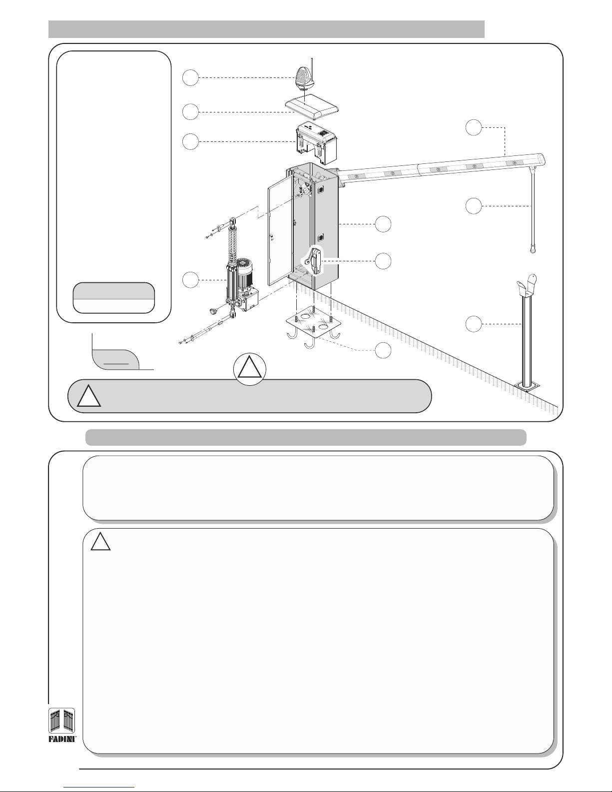
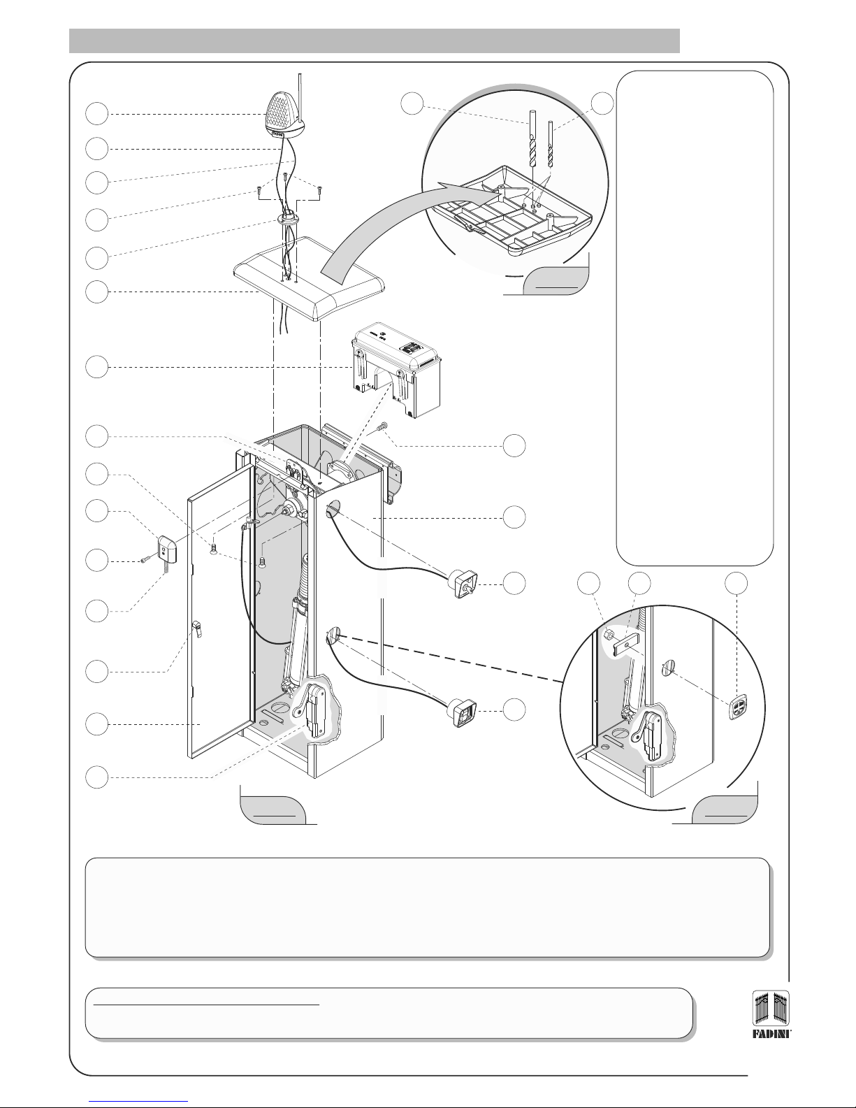
1. Miri 4 flasher with Birio A8
aerial (optional)
2. Housing cabinet cover
3. Accessory control box with
Elpro 980 unit
4. Cos 982 hydraulic control unit
group with hydraulic piston
and oil reservoir
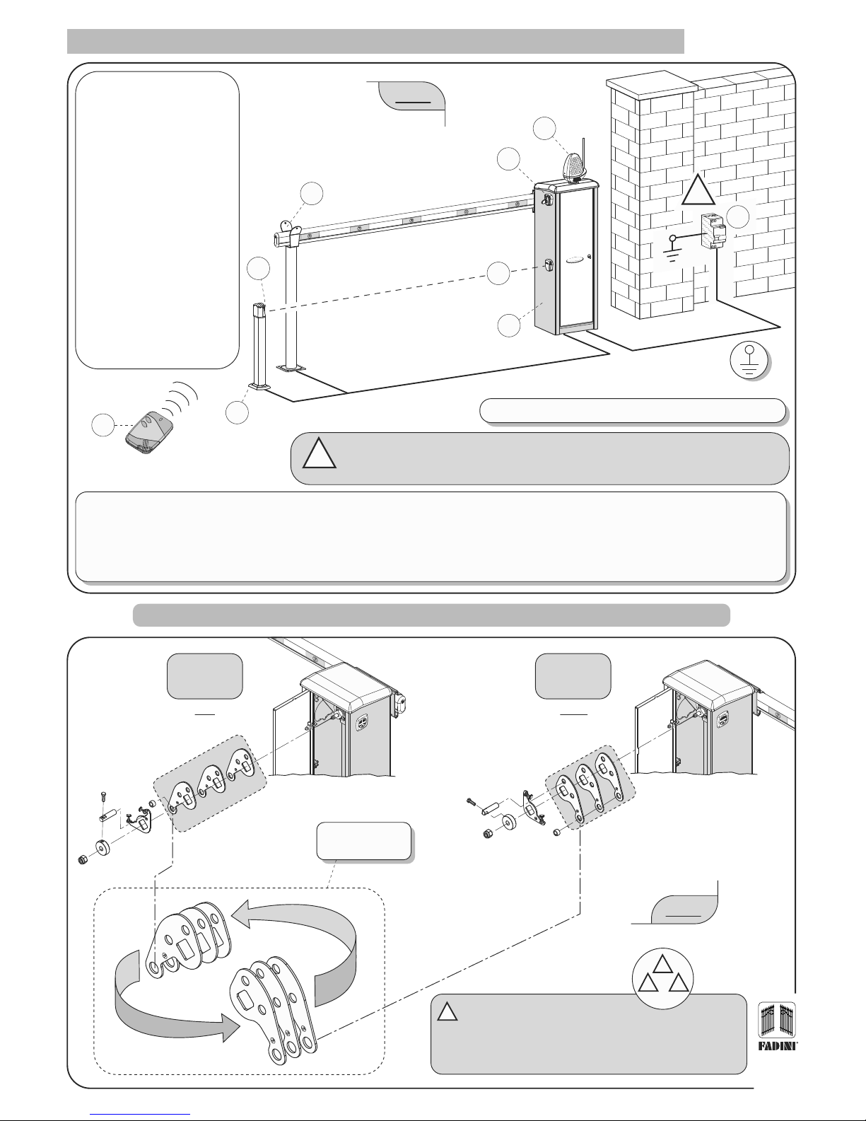
5. Barrier cabinet - right hand
version
6. Cabinet door switch for
general electrical power
disconnection
7. Anchor plate with anchor
bolts
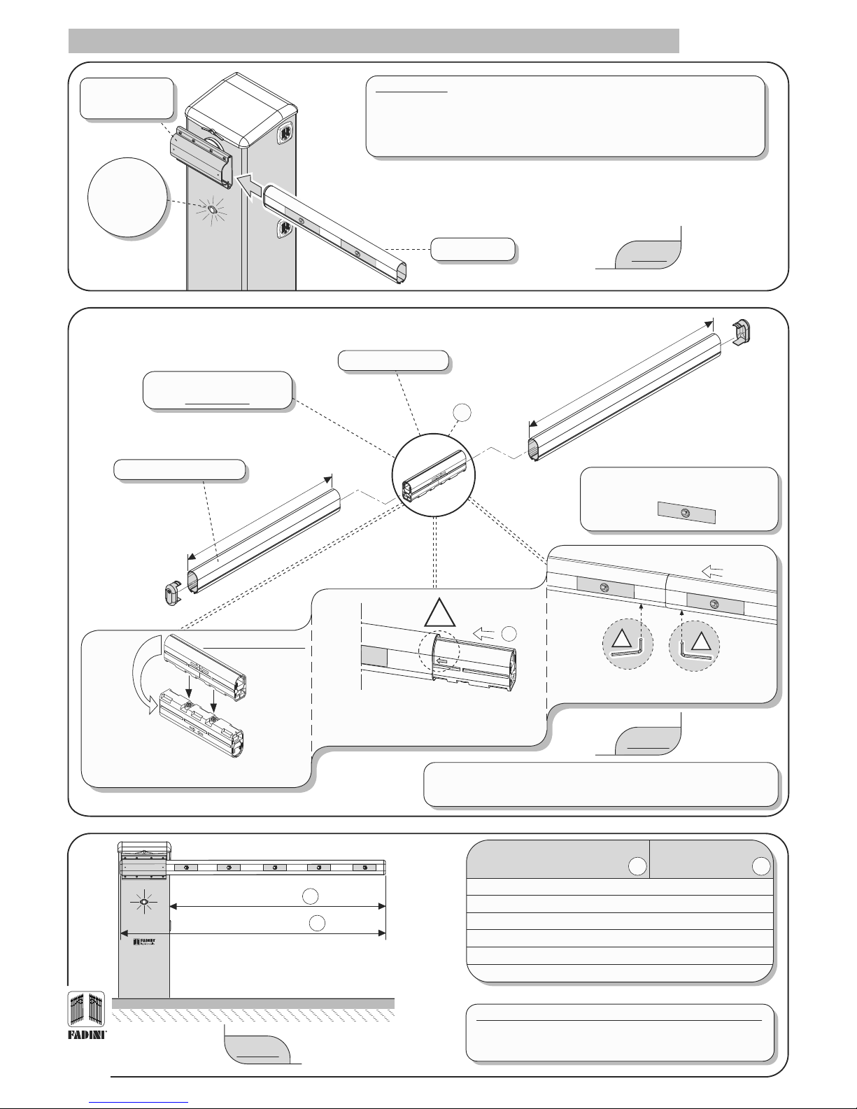
8. Beam arm in R532 anodised
aluminium, made up of two
modules: 2.10 m + 3.20 m
9. Folding leg (optional)
10. Fixed pedestal with yoke
(optional)
1
2
3
4
5
6
7
8
9
10
Bayt 980
Hydraulic
!The firm Meccanica Fadini, as the manufacturing firm, is not responsible for the lack of observance of
proper standards of installation or of applications not indicated in this instruction booklet.
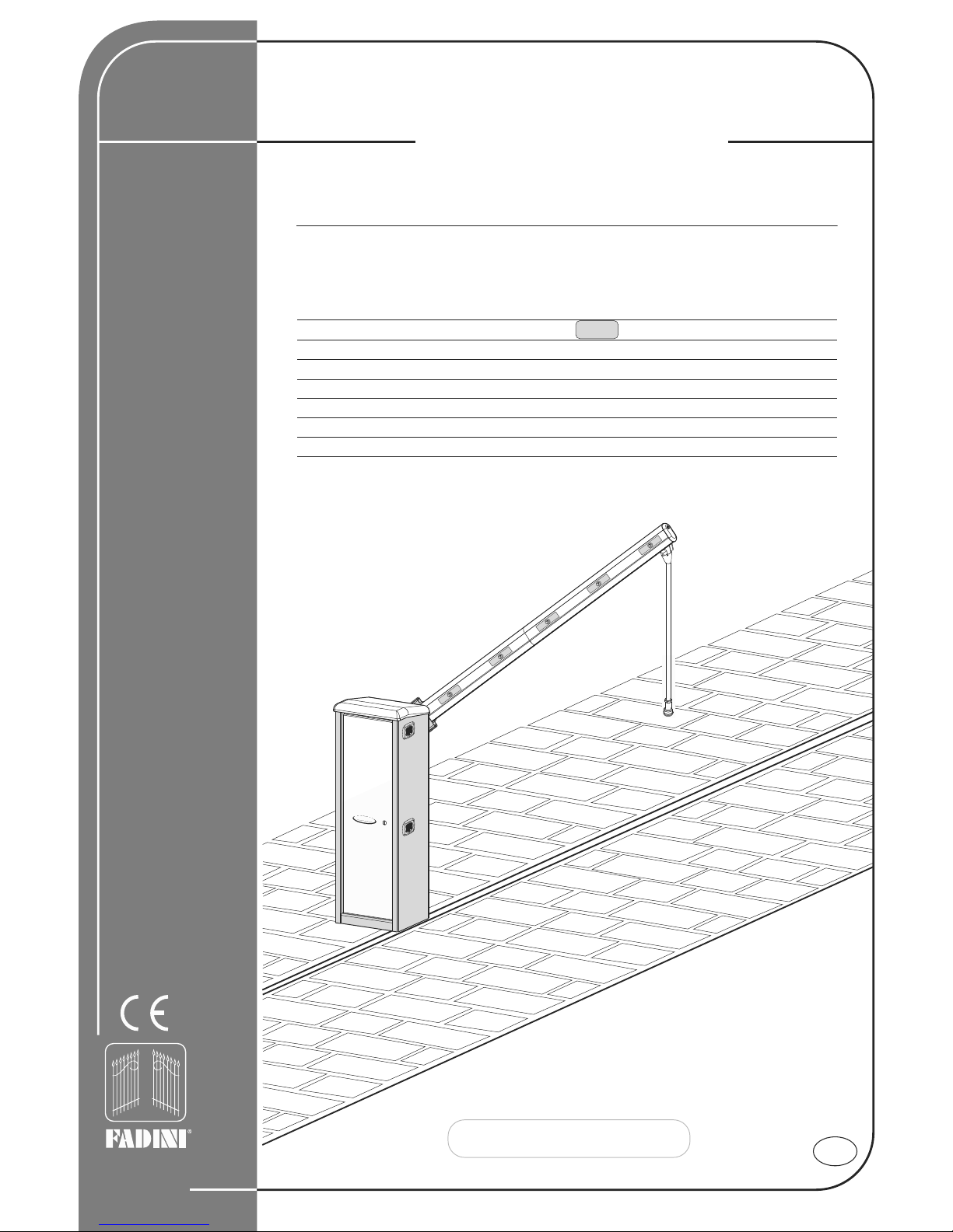
FIG. 1
PRELIMINARY WARNINGS FOR SAFETY AND THE PROPER OPERATION OF THE SYSTEM
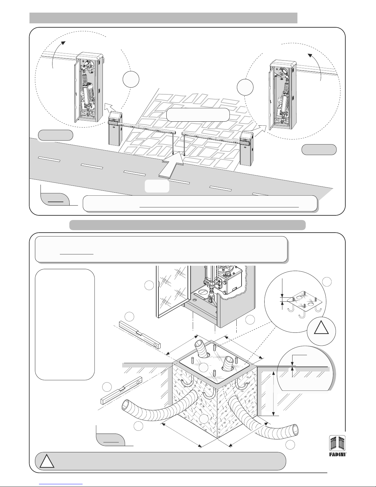
Before proceeding to the actual installation of the automated mechanism in the ground it is necessary to verify as follows:
- The installation, inspection, testing, risk analysis and following maintenance procedures must be performed by qualified and authorised technical
personnel.
- This automated mechanism has been designed for the exclusive use with the minimum required safety, signalling and command accessories, which are
indicted in this booklet.
- Any other application not expressly indicated in this booklet could bring about malfunction or damages to things or persons.
- Check and verify the consistency of the terrain so as to avoid future settling or deformation in the area in which the automated mechanism is to be
installed.
- Check and verify in the immediate vicinity of the site and underneath it that there are no service conduits that could interfere with the necessary excavations
in the ground.
- Verify that, in the immediate vicinity and underneath the site of the installation of the accessories, there are no sources of electromagnetic disturbances,
such that the magnetic/electromagnetic fields of any possible metallic mass detection loops and of all the system command and control electronics for
the device might be masked or unduly influenced.
- Check and verify that the electrical mains supply lines powering the electrical motor are 230V±10% at 50Hz.
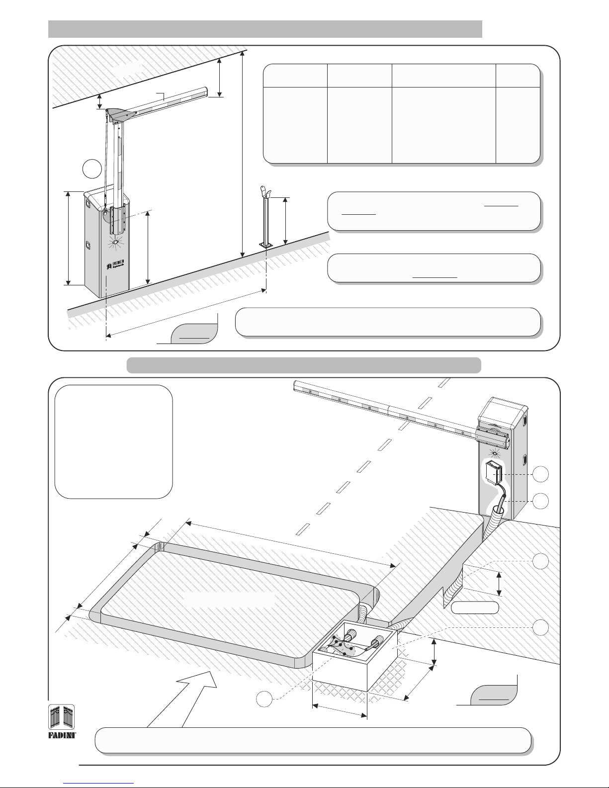
- Electrical power supply for the Bayt 980 must be delivered by way of electrical cables with a section of 1 mm2for a maximum distance of 50 metres. For
distances longer than 50 metres it is recommended that cables with sections suitable for a proper standard of installation be used.
- During the entire movement of the barrier beam there must be no obstacles or aerial contacts that obstruct its movement.
- For any necessary substitutions of elements or accessories, utilise only original components indicated by the manufacturing firm.
- All of the packing material and other waste must be disposed of through specialised firms. Do not dispose of toxic substances into the environment.
The Meccanica Fadini Company is not responsible for any damages brought about by improper utilisation or any use that is not specifically indicated in
this booklet. Furthermore, it will not respond for malfunctions due to the use of materials or accessories not indicated by the same firm.
- The manufacturing firm reserves the right to bring about modifications to this booklet without notice.
- All of the drawings and figures in this booklet are purely indicative and may not represent a real installation. It is the job of the installer to verify them
and adapt them to the actual requirements.
!
FOR PERFECT APPLICATION AND FUNCTION OF THE BAYT 980 IT IS RECOMMENDED THAT THE FOLLOWING EXPLANATION POINTS AND THEIR
RESPECTIVE DRAWINGS FOUND IN THIS INSTRUCTION BOOKLET ARE FOLLOWED.
IMPORTANT: THE ENTIRE INSTALLATION MUST BE PERFORMED BY QUALIFIED TECHNICAL PERSONNEL,
WITH RESPECT FOR THE EN 12453 - EN 12445 SAFETY REGULATIONS
AND MACHINE DIRECTIVE 2006/42/CE.
CARRY OUT A CAREFUL RISK ANALYSIS ACCORDING TO THE REGULATIONS IN FORCE.
!
Made in Italy
the gate opener