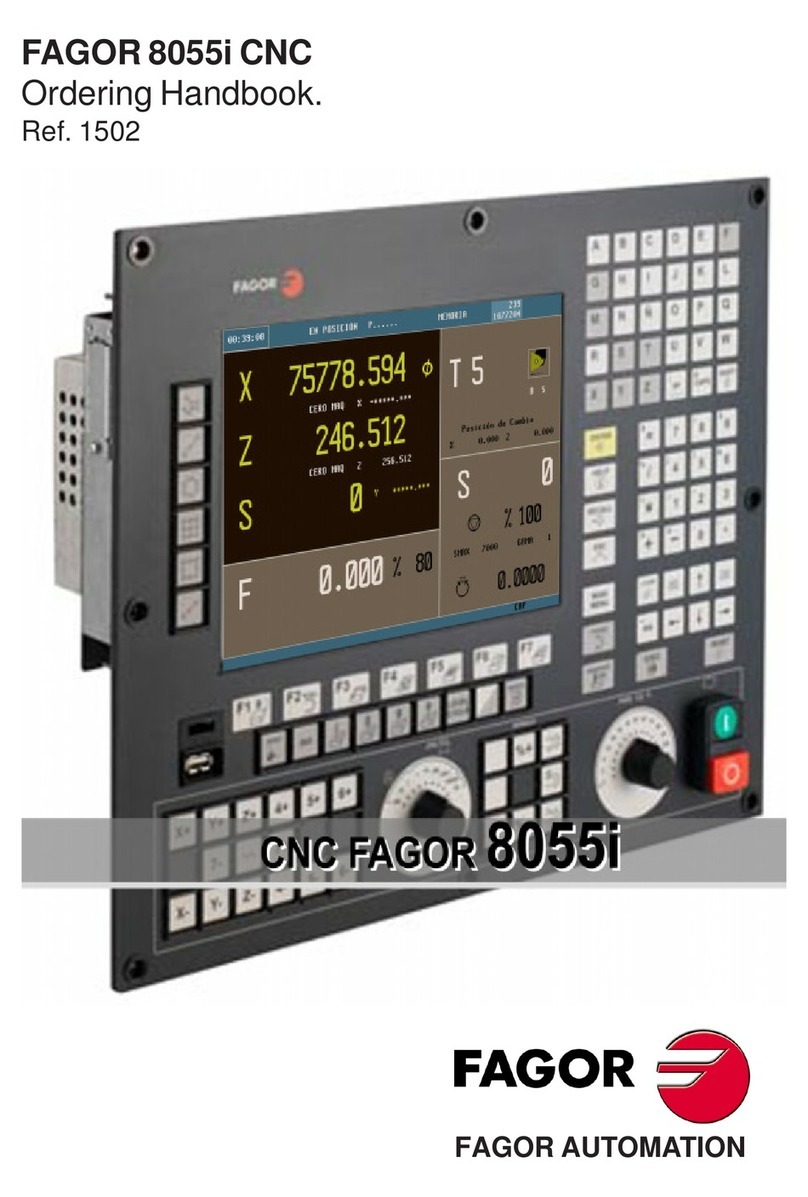
Fagor CNC 8070 Owner's manual

CNC 8070
REF. 0504
(SOFT V02.0X)
PROGRAMMING MANUAL
(Soft V02.0x) Ref. 0504


Unauthorized copying or distributing of this software is prohibited.
All rights reserved. No part of this documentation may be transmitted, transcribed, stored in a backup device
or translated into another language without Fagor Automation’s consent.
Microsoft
®
and Windows
®
are registered trademarks of Microsoft Corporation, U.S.A.
Programming manual


PRELIMINARY WARNINGS
MACHINE SAFETY
It is up to the machine manufacturer to make sure that the safety of the machine is enabled
in order to prevent personal injury and damage to the CNC or to the products connected to it.
On start-up and while validating CNC parameters, it checks the status of the following safety
elements:
• Feedback alarm for analog axes.
• Software limits for analog and sercos linear axes.
• Following error monitoring for analog and sercos axes (except the spindle) both at the
CNC and at the drives.
• Tendency test on analog axes.
If any of them is disabled, the CNC shows a warning message and it must be enabled to
guarantee a safe working environment.
FAGOR AUTOMATION shall not be held responsible for any personal injuries or physical
damage caused or suffered by the CNC resulting from any of the safety elements being
disabled.
HARDWARE EXPANSIONS
FAGOR AUTOMATION shall not be held responsible for any personal injuries or physical
damage caused or suffered by the CNC resulting from any hardware manipulation by
personnel unauthorized by Fagor Automation.
If the CNC hardware is modified by personnel unauthorized by Fagor Automation, it will no
longer be under warranty.
COMPUTER VIRUSES
FAGOR AUTOMATION guarantees that the software installed contains no computer viruses.
It is up to the user to keep the unit virus free in order to guarantee its proper operation.
Computer viruses at the CNC may cause it to malfunction. An antivirus software is highly
recommended if the CNC is connected directly to another PC, it is part of a computer network
or floppy disks or other computer media is used to transmit data.
FAGOR AUTOMATION shall not be held responsible for any personal injuries or physical
damage caused or suffered by the CNC due a computer virus in the system.
If a computer virus is found in the system, the unit will no longer be under warranty.
Programming manual


• • • Programming manual
CNC 8070
(SOFT V02.0X)
i
INDEX
1. Creating a program
1.1 Program structure ..............................................................................................................1
1.2 Block structure ...................................................................................................................4
1.3 Programming in ISO code..................................................................................................5
1.3.1 List of preparatory "G" functions.....................................................................................8
1.4 High-level language programming ...................................................................................11
1.5 Parameters, constants and expressions ..........................................................................13
1.5.1 Arithmetic parameters...................................................................................................14
1.5.2 Operators and functions ...............................................................................................16
1.5.3 Expressions ..................................................................................................................19
2. Machine overview
2.1 Axis nomenclature............................................................................................................21
2.2 Coordinate system ...........................................................................................................23
2.3 Reference systems ..........................................................................................................24
2.3.1 Origins of the reference systems ..................................................................................25
2.4 Home search....................................................................................................................26
2.4.1 Definition of "Home search"..........................................................................................26
2.4.2 "Home search" programming........................................................................................27
3. Coordinate system
3.1 Plane selection (G17/G18/G19/G20) ...............................................................................29
3.1.1 Work plane programming by two directions (G20)........................................................31
3.1.2 Longitudinal tool axis selection.....................................................................................33
3.2 Programming in millimeters (G71) or in inches (G70)......................................................34
3.3 Absolute (G90) or incremental (G91) coordinates ...........................................................35
3.4 Programming in radius (G152) or in diameters (G151)....................................................37
3.5 Coordinate programming .................................................................................................38
3.5.1 Cartesian coordinates...................................................................................................38
3.5.2 Polar coordinates ..........................................................................................................39
4. Origin selection
4.1 Programming with respect to machine zero.....................................................................43
4.2 Fixture offset ....................................................................................................................45
4.3 Coordinate preset (G92) ..................................................................................................47
4.4 Zero offsets (G54-G59/G159)..........................................................................................48
4.4.1 Incremental zero offset (G158) .....................................................................................50
4.4.2 Excluding axes in the zero offset (G157)......................................................................52
4.5 Zero offset cancellation (G53)..........................................................................................53
4.6 Polar origin preset (G30)..................................................................................................54
5. Technological functions
5.1 Machining feedrate (F) .....................................................................................................55
5.2 Feedrate related functions ...............................................................................................57
5.2.1 Feedrate programming units (G93/G94/G95)...............................................................57
5.2.2 Feedrate blend (G108/G109/G193)..............................................................................59
5.2.3 Constant feedrate mode (G197/G196) .........................................................................61
5.2.4 Cancellation of the % of feedrate override (G266)........................................................63
5.2.5 Acceleration control (G130/G131) ................................................................................64
5.2.6 Jerk control (G132/G133) .............................................................................................66
5.2.7 Feed-Forward control (G134) .......................................................................................68
5.2.8 AC-Forward control (G135)...........................................................................................70
5.3 Spindle speed (S).............................................................................................................72
5.3.1 Spindle speed programming.........................................................................................73
5.3.2 Turning speed limit........................................................................................................75

Programming manual
CNC 8070
(SOFT V02.0X)
ii
5.4 Tool number (T)................................................................................................................76
5.5 Tool offset number (D)......................................................................................................79
5.6 Auxiliary (miscellaneous) functions (M)............................................................................81
5.6.1 List of "M" functions ......................................................................................................82
5.7 Auxiliary functions (H) ......................................................................................................88
6. Tool path control
6.1 Rapid traverse (G00)........................................................................................................89
6.2 Linear interpolation (G01) ................................................................................................91
6.3 Circular interpolation (G02/G03)......................................................................................95
6.3.1 Cartesian coordinates (Arc center programming).........................................................97
6.3.2 Cartesian coordinates (Radius programming) ..............................................................98
6.3.3 Polar coordinates ........................................................................................................101
6.3.4 Temporary polar origin shift to the center of arc (G31) ...............................................104
6.3.5 Arc center in absolute coordinates (G06/G261/G262)................................................105
6.3.6 Arc center correction (G264/G265).............................................................................107
6.4 Arc tangent to previous path (G08) ................................................................................108
6.5 Arc defined by three points (G09) ..................................................................................109
6.6 Helical interpolation (G02/G03)......................................................................................111
6.7 Electronic threading with constant pitch (G33)...............................................................113
6.8 Rígid tapping (G63)........................................................................................................115
6.9 Manual intervention (G200/G201/G202)........................................................................117
6.9.1 Additive manual intervention (G201/G202).................................................................118
6.9.2 Exclusive manual intervention (G200) ........................................................................119
7. Geometry assistance
7.1 Square corner (G07/G60) ..............................................................................................121
7.2 Semi-rounded corner (G50)...........................................................................................123
7.3 Controlled corner rounding, radius blend, (G05/G61)....................................................124
7.3.1 Types of corner rounding ............................................................................................126
7.4 Corner rounding, radius blend, (G36) ............................................................................130
7.5 Corner chamfering, (G39) ..............................................................................................132
7.6 Tangential entry (G37) ...................................................................................................134
7.7 Tangential exit (G38)......................................................................................................135
7.8 Mirror image (G11, G12, G13, G10, G14)......................................................................136
7.9 Coordinate system rotation, pattern rotation, (G73).......................................................139
7.10 General scaling factor ....................................................................................................142
8. Additional preparatory functions
8.1 Dwell (G04) ....................................................................................................................145
8.2 Software limits by program (G198-G199).......................................................................146
8.3 Hirth axes (G170-G171).................................................................................................147
8.4 OEM subroutines (G180-G189) .....................................................................................148
8.5 Changing of parameter range of an axis (G112)............................................................150
8.6 Probing (G100)...............................................................................................................151
8.6.1 Include/exclude probe offset (G101/G102).................................................................152
9. Tool compensation
9.1 Tool radius compensation ..............................................................................................157
9.1.1 Functions associates with radius compensation.........................................................158
9.1.2 Beginning of tool radius compensation.......................................................................161
9.1.3 Sections of tool radius compensation .........................................................................165
9.1.4 Change of type of radius compensation while machining...........................................169
9.1.5 Cancellation of tool radius compensation...................................................................171
9.2 Tool length compensation ..............................................................................................174

Programming manual
CNC 8070
(SOFT V02.0X)
iii
10. Canned cycles
10.1 General concepts...........................................................................................................175
10.1.1 Canned cycle definition...............................................................................................175
10.1.2 Influence zone of a canned cycle ...............................................................................176
10.1.3 Canned cycle cancellation..........................................................................................176
10.1.4 Work planes ................................................................................................................177
10.1.5 Programming order.....................................................................................................178
10.1.6 Programming in other planes......................................................................................180
10.2 G81. Drilling canned cycle .............................................................................................182
10.2.1 Programming example................................................................................................183
10.3 G82. Drilling canned cycle with variable peck................................................................184
10.3.1 Programming example................................................................................................188
10.4 G83. Deep-hole drilling canned cycle with constant peck..............................................189
10.4.1 Programming example................................................................................................191
10.5 G84. Tapping canned cycle............................................................................................192
10.5.1 Programming example................................................................................................194
10.6 G85. Reaming canned cycle..........................................................................................195
10.6.1 Programming example................................................................................................196
10.7 G86. Boring canned cycle..............................................................................................197
10.7.1 Programming example................................................................................................198
10.8 G87. Rectangular pocket canned cycle..........................................................................199
10.8.1 Programming example................................................................................................203
10.9 G88. Circular pocket canned cycle ................................................................................205
10.9.1 Programming example................................................................................................209
11. Multiple machining
11.1 G160. Multiple machining in straight line .......................................................................213
11.1.1 Programming example................................................................................................215
11.2 G161. Multiple machining in rectangular pattern ...........................................................216
11.2.1 Programming example................................................................................................219
11.3 G162. Multiple machining in grid pattern .......................................................................220
11.3.1 Programming example................................................................................................223
11.4 G163. Multiple machining in a full circle.........................................................................224
11.4.1 Programming example................................................................................................226
11.5 G164. Multiple machining in arc pattern ........................................................................227
11.5.1 Programming example................................................................................................229
11.6 G165. Multiple machining in a chord pattern .................................................................230
11.6.1 Programming example................................................................................................232
12. Cycle editor
12.1 General concepts...........................................................................................................233
12.1.1 Associate a multiple machining operation with a canned cycle ..................................235
12.1.2 Machining movements................................................................................................237
12.1.3 Selecting data, profiles and icons ...............................................................................238
12.1.4 Value applied when the value of a parameter is 0 ......................................................240
12.1.5 Simulate a canned cycle.............................................................................................241
12.2 Center punching.............................................................................................................243
12.3 Drilling 1. ........................................................................................................................245
12.4 Drilling 2. ........................................................................................................................247
12.5 Tapping...........................................................................................................................249
12.6 Reaming.........................................................................................................................251
12.7 Boring 1..........................................................................................................................253
12.8 Boring 2..........................................................................................................................255
12.9 Simple pocket.................................................................................................................257
12.10 Rectangular pocket ........................................................................................................260
12.11 Circular pocket ...............................................................................................................265
12.12 Pre-emptied pocket ........................................................................................................270
12.13 2D pocket .......................................................................................................................275
12.13.1 Examples of how to define 2D profiles .......................................................................281
12.14 3D pocket .......................................................................................................................284
12.14.1 Examples of how to define 3D profiles .......................................................................291
12.15 Rectangular Boss...........................................................................................................295
12.16 Circular boss ..................................................................................................................300
12.17 Surface milling................................................................................................................304

Programming manual
CNC 8070
(SOFT V02.0X)
iv
12.18 Point-to-point profile .......................................................................................................308
12.19 Profile.............................................................................................................................312
12.20 Slot milling......................................................................................................................315
12.21 Multiple machining in a straight line ...............................................................................320
12.22 Multiple machining in an arc...........................................................................................321
12.23 Multiple machining in a parallelogram pattern................................................................323
12.24 Multiple machining in a grid pattern ...............................................................................324
12.25 Random multiple machining...........................................................................................325
13. Coordinate transformation
13.1 Movement in an incline plane.........................................................................................329
13.2 Kinematics selection (#KIN ID) ......................................................................................331
13.3 Coordinate systems (#CS) (#ACS) ................................................................................332
13.3.1 Coordinate system definition MODE 1........................................................................334
13.3.2 Coordinate system definition MODE 2........................................................................336
13.3.3 Coordinate system definition MODE 3........................................................................338
13.3.4 Coordinate system definition MODE 4........................................................................339
13.3.5 Coordinate system definition MODE5.........................................................................340
13.3.6 Coordinate system definition MODE6.........................................................................341
13.4 How to combine several coordinate systems .................................................................343
13.5 Tool perpendicular to the plane (#TOOL ORI) ...............................................................345
13.6 Using RTCP (Rotating Tool Center Point) ......................................................................347
13.6.1 Considerations about the RTCP function ...................................................................351
13.7 Tool length compensation (#TLC) ..................................................................................352
13.8 Kinematics related variables ..........................................................................................353
13.9 How to withdraw the tool when losing the plane ............................................................354
14. CNC variables
14.1 Understanding the description of the variables..............................................................355
14.1.1 Access to numeric values from the PLC.....................................................................358
14.1.2 Accessing the variables in a single-channel system...................................................359
14.1.3 Accessing the variables of a single-channel system ..................................................361
14.2 Related to general machine parameters........................................................................364
14.2.1 Channel related ..........................................................................................................366
14.3 Related to axis machine parameters..............................................................................368
14.3.1 Related to gear parameters ........................................................................................371
14.4 Related to jog mode parameters....................................................................................374
14.5 Related to "M" function parameters ...............................................................................375
14.6 Related to kinematic parameters ...................................................................................376
14.7 Related to magazine parameters...................................................................................377
14.8 Related to OEM parameters ..........................................................................................378
14.9 User tables related.........................................................................................................379
14.10 Tool related.....................................................................................................................381
14.10.1 Variables only used during block preparation .............................................................383
14.11 PLC related ....................................................................................................................384
14.12 Jog mode related ...........................................................................................................385
14.13 Coordinate related..........................................................................................................387
14.14 Feedrate related.............................................................................................................389
14.15 Related to the spindle speed..........................................................................................390
14.16 Related to the programmed functions............................................................................391
14.17 Related to the independent axes ...................................................................................396
14.18 Related to the machine configuration.............................................................................397
14.19 Other variables...............................................................................................................400
14.20 Alphabetical listing of variables......................................................................................403

Programming manual
CNC 8070
(SOFT V02.0X)
v
15. Statements and instructions
15.1 Programming statements ...............................................................................................414
15.1.1 Display instructions.....................................................................................................414
15.1.2 Enabling and disabling instructions ............................................................................418
15.1.3 Programming referred to machine reference zero (home)..........................................419
15.1.4 Subroutine instructions ...............................................................................................420
15.1.5 Program instructions...................................................................................................425
15.1.6 Electronic axis slaving ................................................................................................427
15.1.7 Axis parking ................................................................................................................429
15.1.8 Axis swapping .............................................................................................................431
15.1.9 Spindle swapping........................................................................................................436
15.1.10 Selecting the master spindle of a channel ..................................................................439
15.1.11 Longitudinal tool axis selection...................................................................................440
15.1.12 "C" axis: Activate the spindle as "C" axis....................................................................441
15.1.13 "C" axis: Machining of the face of the part..................................................................443
15.1.14 "C" axis: Machining of the turning side of the part......................................................445
15.1.15 Collision detection.......................................................................................................447
15.1.16 Related to manual intervention ...................................................................................449
15.1.17 Splines (Akima)...........................................................................................................452
15.1.18 Polynomial interpolation..............................................................................................455
15.1.19 High speed machining ................................................................................................456
15.1.20 Acceleration control ....................................................................................................458
15.1.21 Coordinate transformation ..........................................................................................460
15.1.22 Definition of macros ....................................................................................................463
15.1.23 Block repetition ...........................................................................................................465
15.1.24 Communication and synchronization between channels............................................468
15.1.25 Movements of independent axes ................................................................................472
15.1.26 Additional programming instructions...........................................................................476
15.2 Flow controlling instructions...........................................................................................479
15.2.1 Jump to a block ($GOTO) ...........................................................................................479
15.2.2 Conditional execution ($IF).........................................................................................481
15.2.3 Conditional execution ($SWITCH) ..............................................................................483
15.2.4 Block repetition ($FOR) ..............................................................................................484
15.2.5 Conditional block repetition ($WHILE)........................................................................485
15.2.6 Conditional block repetition ($DO) ..............................................................................486
16. Probing canned cycles.
16.1 Tool calibration ...............................................................................................................488
16.1.1 Measure or calibrate the length of a tool. ...................................................................489
16.1.2 Measure or calibrate the radius of a tool. ...................................................................492
16.1.3 Measure or calibrate the radius and length of a tool...................................................494
16.2 Probe calibration ............................................................................................................497
16.3 Surface measuring canned cycle...................................................................................500
16.4 Outside corner measuring canned cycle........................................................................504
16.5 Inside corner measuring canned cycle ..........................................................................507
16.6 Angle measuring canned cycle......................................................................................510
16.7 Outside corner and angle measuring canned cycle.......................................................513
16.8 Hole measuring canned cycle........................................................................................516
16.9 Boss measuring canned cycle .......................................................................................519


CNC 8070
(SOFT V02.0X)
I
ABOUT THIS MANUAL
Title
Programming Manual.
Type of documentation
It describes functions and instructions of the CNC language.
Internal code
It is part of the manual directed to the enduser. The code ofthe manual
depends on the software version –standard– or –advanced–.
Version
It corresponds to the software version: (Soft V02.0x).
Start-up
Warning
CNC 8070 USER (IN) STAN Code 03753611
CNC 8070 USER (IN) AVANZ Code 03753631
Verify that the machine that integrates this CNC meets the
89/392/CEE Directive.
Before starting up the CNC, read the instructions of chapter 1 in the
Installation Manual.
The information described in this manual may be changed due to
technical modifications.
FAGOR AUTOMATION, S. Coop. reserves the right to make any
changes to the contents of this manual without prior notice.


CNC 8070
(SOFT V02.0X)
III
ABOUT THE PRODUCT
Software options
Bear in mind that some of the features described in this manual
depend on the software options that are installed.
“M” model “GP” model
Number of execution channels 1 to 4 1 to 4
Number of axes 4 to 28 4 to 28
Number of spindles 1 to 4 1 to 4
Number of tool magazines 1 to 4 1 to 4
COCOM version Option Option
Sercos digital drive system Option Option
Tool radius compensation Standard Option
"C" axis Standard Not available
RTCP transformation Option Not available
High speed machining (HSC). Option Option
Probing canned cycles Option Not available
Tandem axes Option Not available
Synchronism and cams Option Not available


CNC 8070
(SOFT V02.0X)
V
VERSION HISTORY
Here is a list of the features added in each software version and the manuals that describe them.
The version history uses the following abreviations:
Software V01.0x February of 2002
First version.
Software 1.1x September of 2002
INST Installation manual
PRG Programming manual
OPT Operation manual
Feature
Probe management through a digital input. It is not possible to manage it through the
“Counter” module connector.
INST
Set the numbering of the digital I/O. INST
Kinetics for rotary table. INST
Possibility to park and unpark SERCOS axes from the PLC. INST
Keyboard simulation from the PLC. INST
New treatment of the JOG panel (Key + Direction). INST / OPT
New machine parameters.
• Probe setting.
• Numbering of the digital I/Os.
• Kinetics for rotary table.
• Repositioning feedrate after a tool inspection.
INST
New variables.
• Probe setting.
• Numbering of the digital I/Os.
• Key simulation.
• Repositioning feedrate after a tool inspection.
• General scaling factor.
• Kinetics dimensions.
INST
PRG
General scaling factor (#SCALE). PRG
Pobring canned cycles (#PROBE). PRG
Probe selection (#SELECT PROBE). PRG
Programming of warnings (#WARNING). PRG
Block repetition ($RPT). PRG
Improved programming of high speed machining (#HSC). PRG
Improved programming of axis swapping (#SET AX, #CALL AX, #FREE AX, #RENAME). PRG
Macros: The number of macros in a program is now limited to 50. PRG
Improved tool table. OPT
Protection passwords. OPT
Manual mode (jog). Tool calibration with or without probe. OPT
Manual mode (jog). Automatic loading of zero offsets table. OPT

VIII
CNC 8070
Version history
(SOFT V02.0X)
VI
January of 2005 Software: 2.0x
Manual mode (jog). Programming of feedrate “F” and spindle speed “S”. OPT
Axis selection/deselection for handwheel jog. OPT
Theoretical path simulation. OPT
Definition of the first block of a block search. OPT
Confirm that the CNC is not in automatic mode when executing a program. OPT
Syntax check in MDI. OPT
Feature
Feature
Operation under Windows XP INST
Emergency shutdown with battery (Central unit PC104) OPT
New languages (Basque and Portuguese) INST
Multi-channel system, up to 4 channels.
• Spindle swapping
• Axis swapping
• Communication and synchronization between channels.
• Common arithmetic parameters.
• Access to variables per channel.
INST
PRG
OPT
Multi-spindle system, up to 4 spindles PRG / INST
Tool management with up to 4 magazines. INST
Tandem axis. INST
New kinematics table-spindle (TYPE13 to TYPE16). INST
New kinematics for C axis (TYPE 41 to TYPE 43) INST
Parameter matching between the CNC and the Sercos drive INST
New machine parameters.
• Warning level on Gantry axes (WARNCOUPE)
• Placing the vertical softkeys on the right or on the left (VMENU).
• Apply cross compensation to either theoretical or real coordinates (TYPCROSS).
• Apply leadscrew compensation to either theoretical or real coordinates (TYPLSCRW).
• Defining the default compensation mode (IRCOMP).
• Defining the type of reference pulse (REFPULSE).
• Memory sharing between applications (PLCDATASIZE).
• Generic OEM machine parameters (MTBPAR).
• Reading Sercos variables from the CNC (DRIVEVAR).
• Backlash peak compensation (BAKANOUT, BAKTIME, ACTBAKAN).
INST
The behavior of rotary axes has been changed. Machine parameters AXISMODE,
UNIDIR, SHORTESTWAY.
INST
Possibility of Sercos transmission at 8 Mhz and 16 Mhz. Parameter SERBRATE. INST
Define the anticipation time for the axes to be considered to be in position. Machine
parameter ANTIME and the PLC mark ADVINPOS.
INST
The "(V.).TM.MZWAIT " variable is not necessary in the subroutine associated with M06. INST
Filters to eliminate the resonance of the spindle when it works as C axis or in rigid tapping. INST
PLC. The TMOPERATION may take the values 13 and 14. INST
PLC. New mark MMCWDG to detect that the lockup of the operating system. INST
PLC. Accessing arithmetic parameters and OEM parameters with CNCRD returns the
value multiplied by 10000 (reading in float mode).
INST
PLC. The CNCEX command and the FREE mark to execute a CNC block.
New commands at the PLC.
• New mark to disable the cross compensation tables (DISCROSS).
• New mark to correct the parallelism on Gantry axes (DIFFCOMP).
• Definition of external symbols (PDEF).
INST
New variables.
• Software version.
• Variables to be set via PLC.
• Variables for adjusting the position.
• Fine adjustment variables.
• Feedback inputs.
INST / PRG

CNC 8070
Version history
(SOFT V02.0X)
VII
Electronic-cam editor. INST
Optimize the reading and writing of variables from the PLC. Only the following will be
asynchronous.
• The tool variables will be read asynchronously when the tool is neither the active one
nor in the magazine.
• The tool variables will be written asynchronously whether the tool is the active one or
not.
• The variables referred to local arithmetic parameters of the active levels will be read
and written asynchronously.
INST / PRG
Spindle parking and unparking. INST
The RESETIN mark is not necessary to park/unpark axes or spindles from the PLC. INST
Sercos control in velocity. INST
Behavior of the beginning and end of tool radius compensation when not programming
a movement.
PRG
Changing the type of radius compensation while machining. PRG
Via program, loading a tool in a specific magazine position. PRG
Programming of modal subroutines (#MCALL). PRG
Executing a block in a channel (#EXBLK). PRG
Programming the number of repetitions in the block (NR). PRG
Direct resolution of 2D and 3D pockets without requiring a softkey. PRG
Simulating a canned cycle of the editor separately. PRG
New method to jog the axes using the JOG keyboard. Axis keys and independent
directions.
INST / OPT
Importing DXF files from the program editor or from the profile editor. OPT
Importing programs of the 8055/8055i CNC from the program editor. OPT
Use a softkey to select the repositioning of the spindle after tool inspection. OPT
Backup-restore utility. OPT
Improved profile editor. OPT
Assistance in the program editor. Contextual programming assistance.
• When programming "#", it shows the list of instructions.
• When programming "$", it shows the list of instructions.
• When programming "V.", it shows the list of variables.
OPT
Specific password for the machine parameters for kinematics. OPT
Save the CAN configuration for testing it when starting up the system. OPT
The diagnosis mode shows detailed information on the Sercos connection (Type and
version of the drive and motor connected to it).
OPT
It is possible to print all the information on the configuration from any section of the
diagnosis mode.
OPT
It is possible to simulate a cycle separately from the cycle editor. OPT
Setup assistance.
• Oscilloscope.
• Bode diagram.
• Circularity (roundness) test.
OPT
Feature

VIII
CNC 8070
Version history
(SOFT V02.0X)
VIII
April 2005 Software: 2.03
Feature
New values of machine parameter SERPOWSE for the "Sercos II" board. INST
Independent-axis programming commands. INST
Electronic-cams programming commands. INST
New signals that may be consulted and changed for the independent interpolator
(electronic cam and independent axis)
INST
The simulated axes are ignored regarding the validation code.
When unifying parameters, G00FEED and MAXVOLT are not sent out to the drive. INST
Electronic-cam programming instructions (#CAM ON / #CAM OFF). PRG
Independent-axis programming instructions (#MOVE ABS / #MOVE ADD / #MOVE INF
/ #FOLLOW ON / #FOLLOW OFF).
PRG
G112. Change the drive’s parameter set . PRG
DDSSETUP mode OPT
G31. Temporary polar origin shift to the center of interpolation. PRG
Other manuals for CNC 8070
9
Table of contents
Other Fagor Controllers manuals