Trane Tracer UC400 Installation and operating instructions
Other Trane Controllers manuals
Trane
Trane Tracer MP581 User manual
Trane
Trane TCONT 800 Series Quick setup guide

Trane
Trane TCONT 800 Series Installation and operating instructions
Trane
Trane ComfortLink II XL1050 User manual
Trane
Trane CONTH01AAUTOA Assembly instructions
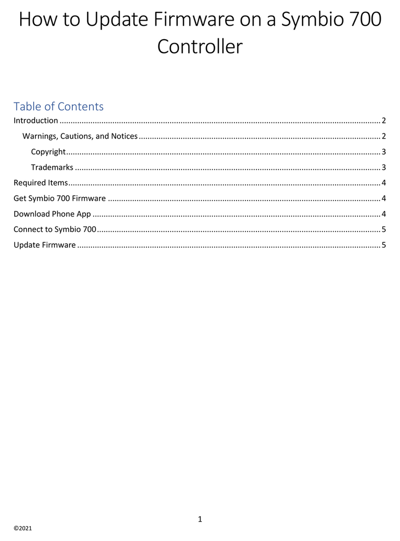
Trane
Trane 700 Use and care manual
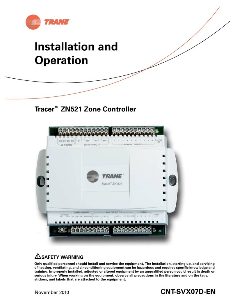
Trane
Trane Tracer ZN521 Owner's manual
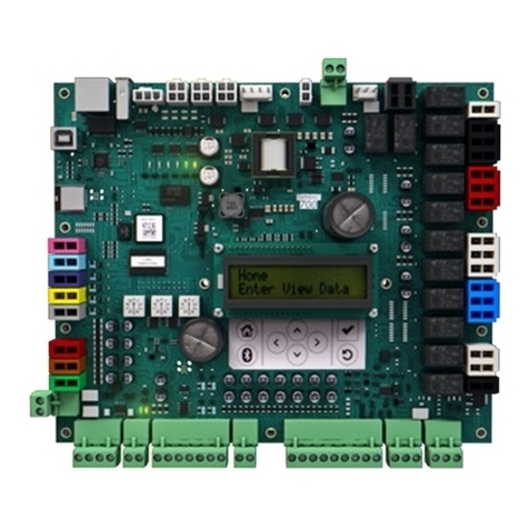
Trane
Trane 700 User guide
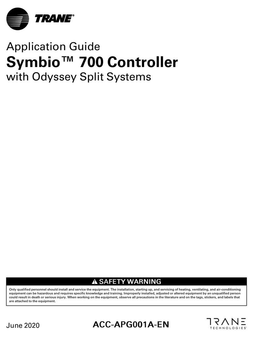
Trane
Trane 700 User guide

Trane
Trane 700 User manual
Trane
Trane Picco R3206A User manual
Trane
Trane Tracer CH535 User manual
Trane
Trane Tracer ZN511 Owner's manual

Trane
Trane Tracer ZN511 User manual
Trane
Trane Tracer UC600 Quick setup guide

Trane
Trane TCONTCCMHCM04A User manual
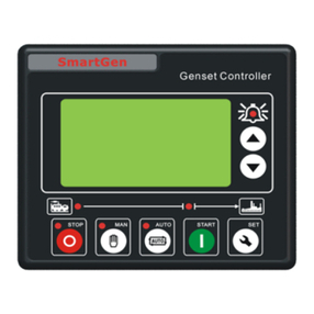
Trane
Trane SmartGen HSC940 User manual
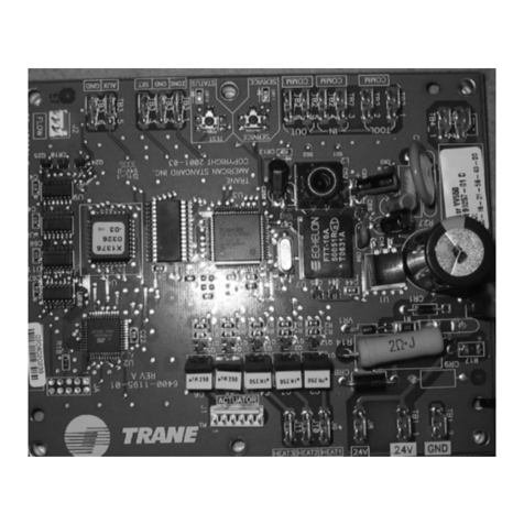
Trane
Trane VAV VV550 LonTalk User manual
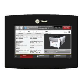
Trane
Trane Tracer TD7 User manual

Trane
Trane Tracer MP581 User manual
Popular Controllers manuals by other brands

Digiplex
Digiplex DGP-848 Programming guide

YASKAWA
YASKAWA SGM series user manual

Sinope
Sinope Calypso RM3500ZB installation guide

Isimet
Isimet DLA Series Style 2 Installation, Operations, Start-up and Maintenance Instructions

LSIS
LSIS sv-ip5a user manual

Airflow
Airflow Uno hab Installation and operating instructions
