Falcon F18 User manual

Owner’s Manual
Revision Date: 2013-02-06
Copyright 2012 – Falcon Marine LLC – 9008 Marlin St. – Cape Canaveral, FL 32920 USA – 321-799-4841

Falcon Marine LLC
The Falcon F18 is a performance boat built and designed for racing. A basic understanding and
knowledge of spinnaker rigged performance sail boats is required to properly set up this vessel and
operate it safely. The F18 is not recommended for beginner and novice crews. Contact the factory
or your closest Falcon representative if you have any questions regarding how this boat should be
assembled, set-up or operated. Improper use or set-up of this boat can result in damage, injury or
even death.
Falcon Marine LLC
Falcon F18
This manual covers the basic assembly of the
above listed models. Before starting assembly,
familiarize your self with the contents of the
containers and the steps in this manual. There
are variations between models and may be some
minor variations based on model year and
options, be sure to follow the appropriate
procedures where applicable.

Table of Contents
1.0 Contents
2.0 Hull Assembly
3.0 Trampoline Assembly
4.0 Line Feeds and Rings
5.0 Trap Bungee
6.0 Mast Rotation
7.0 Mast Assembly
7.1 Spreaders
7.2 Diamond Wires
7.3 Main Halyard
7.4 Spin Halyard
7.5 Standing Rigging
7.6 Bridal Assembly
8.0 Stepping the Mast
9.0 Rudders
9.1 Surf System
9.2 Rudder Alignment
10.0 Spin Pole
11.0 Jib Sheet System
11.1 Jib Rotation Limiter
11.2 Jib Sheet
12.0 Boom and Outhaul
13.0 Downhaul Assembly
14.0 Mast Rotation Quick Release connection
15.0 Mainsail
16.0 Raising the Mainsail
17.0 Lowering the Mainsail
18.0 Mainsheet
19.0 Downhaul
20.0 Outhaul
21.0 Jib
22.0 Spinnaker
22.1 Halyard Run
22.2 Tack Run
22.3 Tack Release
22.4 Attaching the Spin
23.0 Spin Sheet
24.0 Righting line
25.0 Sailing and Beaching
26.0 Righting After a Capsize
27.0 Trailering and Storage
28.0 Design Category
29.0 Maintenance
30.0 Warranty

1.0- Contents
Box contents as they are unpackaged
Some parts may vary slightly from what is pictured.
The exact contents may differ depending on model and options.
Hulls, Line and rigging kit, Spars, Foils, Castings and tramp. Sails and spin hoop not
shown.
For assembly you will need:
Pliers, Socket or box wrench (3/4”), Phillips head screw driver, Tape measure, level, and
Silicone sealant.

2.0– Hull Assembly
After unpacking the hulls, verifying the contents and verifying they did not receive any
damage in transport, find a flat level area to begin the assembly of your boat. Using
the foam end blocks set the hulls so they are parallel and approximately 84 1/2” apart
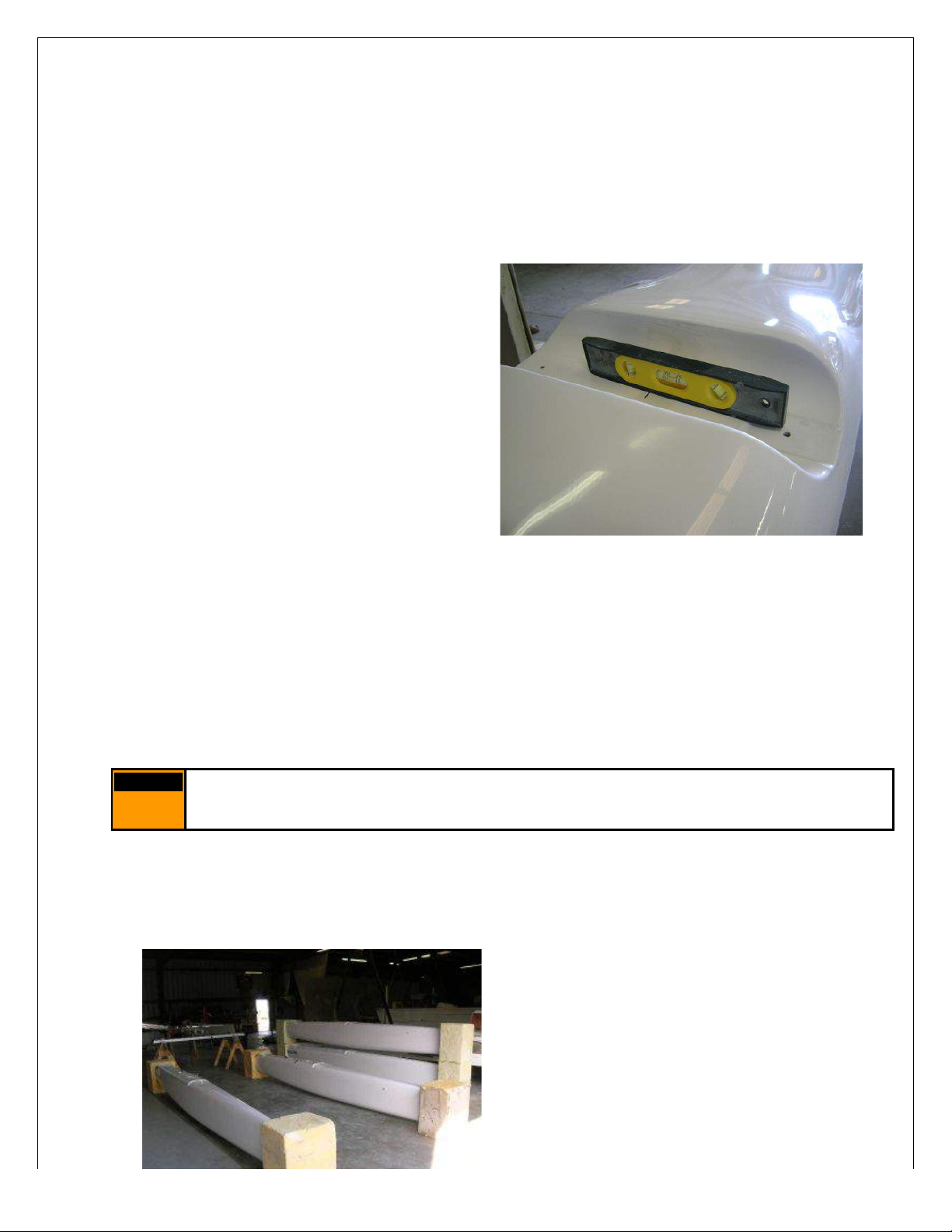
as measured from the centerline of each hull. The hulls of the F18 are canted outboard
3 degrees. Use a wedge on the base of the foam blocks to set the hulls so that they
are at this 3 degree canted position. To verify the placement of the hulls, use a bubble
level placed in the beam pocket of each hull. The pocket base will be level once the
hulls are adjusted to the proper degree of
cant. If you do not have the foam
shipping blocks, place the hulls on
carpet, foam blocks, or other smooth item
where they can be moved without
damaging the surface. You can use
towels or wedges to ensure that the hulls
are set parallel and at the same pitch
angle relative to each other.
With a tape measure first check the
width, then make sure that they are
positioned the same fore and aft, by
taking opposing diagonal measurements
from the same location on each hull. Note, that once the hulls are canted to the proper
3 degrees, the width measurement along the hull centerline will not be same along the
length due to the contour of the hull shape. It is important to try and start with the hulls
as close to the final position as possible. The beams have been prefit at the factory
and the beam sockets in the hulls have very little slop. If they are positioned correctly,
the beams will drop right in place, The forward beam pocket is much deeper and may
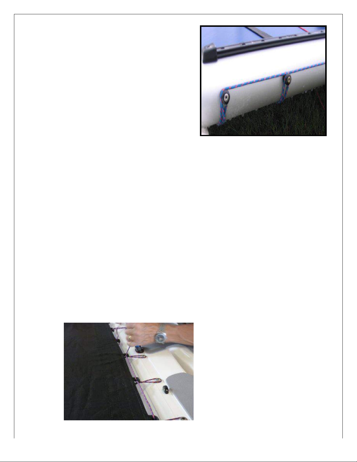
be snug. Note: on the rear beam, the tramp lacing buttons should be aligned to the aft
end. On the front beam the traveler track should be placed forward.
(Figure 2.A).
Once the hulls are set, remove the end
caps and the bolts from the cross bars and
set on the hulls. Dry fit the bolts to ensure
everything will fit smoothly. The hulls were
pre-assembled in the factory, so if they are
aligned properly, the bolts should slide
smoothly into the hulls. After you are
confident of the fit, lift the beams and place
Warning: Properly align the hulls before installing beams using the bolts or
forcing the beams to align the hulls may cause serious structural damage.
Warning

a bead of silicone around the bolt holes and another small amount around the
perimeter of the beam landings. This will seal the holes to help prevent minor leaking
of the boat. Now install the bolts and tighten to 18 to 20 ft/lbs with a torque wrench,
always making sure the hulls have not shifted. Note these bolts need to be kept tight.
They may need tightening after the boat has been sailed few times. They should settle
in after a few sails.
Figure 2B Figure 2C
3.0 – Trampoline Assembly
Fig 3A
After the cross bars are adequately
tightened, now it is time to string the
trampoline. Find the edge on the
tramp with 5 large scallops. Center
the middle scallop around the center
of the cross beam at the mast step
post. The tramp will wrap around the
front of the cross beam and the then
hook the loops on the tramp over each
of the corresponding buttons located
on the back face of the trampoline.
(Figure 3.A)
Now feed the 6’ long fiberglass rod
into the pocket located on the aft end
of the tramp, and center between the
hulls.

In the rigging box, locate a bundle
of lines labeled “Tramp Lacing”.
This bundle should contain:
1 piece 25 foot long
2 pieces 12 foot long
2 or 3 pieces 30 inches long
Begin by lacing the rear of the
trampoline first. With the 1, 25 foot
long piece, tie a loop and wrap
around one end of the tramp tie
rod. (It will be helpful later if you
leave 12-18” of extra line at the
starting end of your loop) Pull the
line snug and bring back under the
rear cross bar and wrap over the
first of the tramp lacing buttons
located on the aft side of the cross
bar. Bring the line forward and
wrap over the exposed end of the
fiberglass rod, and then back to
the first lacing button again. Pull
the line over the top of the first
button and string over the top of
the second. Once over the top of
the second, go back under the
cross bar and wrap around the
fiberglass rod at the first notch,
bringing it back to the second
button, over this button then to the
third. (Figure 3.B)
Continue across the entire tramp
finishing the opposite side in a
mirror of the start. This does not
need to be pulled tight yet at this
stage.
Second locate 1 of the 12 foot long lines and tie one end to the most forward loop
on the side of the trampoline. This line will then feed to the first tramp lacing button
on the top deck of the hull. Wrap the line around the button and then bring it back
through the first loop. From there move the line to the second loop and repeat
down the full number of buttons on the deck. Fig 3C
Fig 3C
Fig 3.B

Repeat this procedure on the opposite hull.
Note at this point the tramp will be loose. Make sure that the trampoline and tie bar
are centered between the hulls.
Now proceed to tighten the rear and then each side lacing taking care to keep the
trampoline and tie bar centered between the hulls. This will likely take several
iterations to get a new trampoline to pull tight. Take care as you are tightening to
keep both the tramp and the tie bar centered between the hulls.
After the tramp is sufficiently tightened use the tails of extra line to wrap around the
end of the trampoline bar to prevent the first and last loop from slipping off the ends.
Once the tramp is laced, remove the 1/8” x 30” lines and tie the foot straps to the
saddles provided on the rear cross bar. Fig 3D
4.0– Line Feeds and Rings
In the rigging box locate the bundle of 3mm bungee and rings labeled “Convenience kit”
Using 1 of the 2mm x 600 long lashing lines, tie the 50mm stainless steel ring to saddle
located on the center of the aft face of the forward cross beam.
It is important to maintain a tight trampoline on these
boats. New trampolines will stretch a fair amount and
it may be necessary to tighten your trampoline after
each of the first few sails after it has been strung

Locate 2 of the 30mm stainless rings and lash them similarly to the trampoline tie bar at
each of the outer most cut outs. Note: Place the lashing outboard of the trampoline tie
line, on each side, to prevent the ties from wearing on the trampoline.
Set aside the remainder of the kit to install in later steps.
Rear – same both sides of tramp Front – At beam center
5.0 – Trap Bungee
In the rigging box are 2 sets of
bungees labeled Trap bungee. The
longer ones are designated for the
forward cross beam, or the crew
bungee, String the forward bungee
through the front cross bar. Open the
beam end cap and tie 1 end of the
bungee to the screw post located just
forward of the bolt. Run the bungee
through the center of the beam to the
opposite side and feed through the
pivot cheek block fastened just aft of
the main bolt. Feed the line back
through the beam and exit through the
end cap in the 7mm bushing. Install a
20mm stopper ball and hog ring as
shown to finish. Perform this same
procedure on both sides of the beam.
Fig 4A Note that with the race kit the
forward bungee system may already
be routed in the beam.
The rear trap bungee will be fed
through the fairlead located on the hull
deck just forward of the dagger board
trunk, and led under the trampoline
forward and through the 50mm
stainless ring lashed to the center of
the forward cross bar. Feed the
bunge then aft to the opposite corner
and tie to aft outboard 30mm stainless
ring lashed to the trap tie bar. The
starting end of the bungee will be
finished with a 20mm stopper ball and
hog ring as shown. Perform the same
procedure to install the bungee on the
opposite side. (Figure 4.B)

Fig 4A Fig 4B
6.0 – Mast Rotation
Find the 5/32” (4mm)line labeled “Mast Rotation”. Feed this line through the cleat
located on the hull just aft of the dagger board trunk, and then under the tramp. Bring
the line back up through the tramp at the grommet located in the center of the tramp
just aft of the storage pocket. Run this line through the turning block provided and back
through the center grommet, under the tramp and back up through the cleat on the
opposite hull.
Note: the turning block will be attached to the line run through the mast rotation arm on
the mast after the mast is stepped to control rotation.

7.0 – Mast Assembly
7.1 - Spreaders: Attach the spreader arms to the fittings located approximately ½way
up the mast. Use the barrel nut to adjust the rake of the spreaders such that they are
equally positioned and a straight edge placed between them will provide a gap of
approximately 56mm measured between it and the mast. The spreader arm should be
approximately 450mm in length.
7.2 - Diamond wires: To install the diamond wires, first remove the base plate from the
bottom of the mast. Feed the threaded stud end end of the diamond wire into 2 slots
located approximately 6” from the bottom, 1 diamond on each side of the mast. Thread
the studs into the bronze adjuster nut and connect the long bolt through the base and
into the center hole of the adjuster nut. Start with the wire studs just even with the
bottom face of the nut. At this point do not secure the lock nuts located on the studs.
( Make sure the assembly is fully extended so that you have room to make the
attachment at the top.)

Once the yoke is attached slide the whole base assembly back onto the mast extrusion
and secure with the 2 #10 screws on the side.
2/3rds of the way up the mast is located 2 strap plates for the upper diamond wire
attachment. Pull the diamond wire up and insert the clevis pin to attach wires to the
plates. (Note at this point you may want to
place a small piece of tape over the pin to keep it from falling out and delay installing
the split rings until all of the mast diamond adjustments have been made.) Once the
top and bottom are secured, you will place the diamond wire over the ends of the
spreader bars. Locate the wire in the center position at the spreader tips.
Using the adjuster nut located on the bottom of the mast base, tighten the system until
there is gentle pressure on the mast and most and all the slack is removed from the
wires.
Site up the mast. If there is a significant side bow in the mast, adjust it now. If the side
bow is slight, continue setting the rake and the final bow adjust will be made later in the
procedure.
To adjust for side bow on the wires: Note the direction the mast is bowing and then
loosen the diamond adjuster bolt; the direction the mast is bowing will now be referred
to the “short” side. Unpin the clevis pin at the upper diamond attachment from the
“long” side. Turn the wire clock wise to shorten the assembly on this side. Make sure
the threaded stud is turning in the block as you rotate the wire. Repin the diamond wire
to the strap, tighten the adjuster bolt again and note the new straightness of the mast.
At this point it just needs to be close.
Start with the extension on the mast spreader arms at its inner most setting. Carefully
measure the distance from the mast track to the center of each wire at the spreader
attachment. This distance should be the same measured on both sides. If one is
longer than the other adjust the rake on one side with the barrel nut adjusters until they
are the same. Note: these measurements are made from the location of the wire, and
not the end of the retention clips on the spreaders. Make sure both are set at the
same angle, as failure to do so may put a permanent twist in the mast when wire
tension is applied. Place a straight edge across the diamond wires and measure the
distance from this to the mast track. Start with a measurement of approximately 56mm.

If the track to wire setting is the same on both sides, you can adjust the barrels equally
on each side until the desired rake is attained.
Once the spreaders arms are even on both sides and the desired starting rake is
achieved, apply slightly more tension from the diamond adjuster bolt at the mast base.
At this point carefully sight up the mast and verify that there is not a bow side to side.
Using the same procedure above make any final adjustments to the wire length to
ensure the mast is straight. Once you are happy with the straightness of the mast and
the settings of the diamonds, you can tighten the jam nuts located on the threaded
studs against the top of the adjuster nut.
Tighten the diamond wires to approximately 36 on the pro Loos gage, approximately
500-600 lbs of tension.
Note that all of these mast settings are approximate for starting your rigging procedure.
Please refer to the tuning manual for the latest settings being used in varying
conditions. Also note small differences may be required to match your particular sail to
the mast. Different sail maker combinations could require significantly different starting
points to accurately match you rig to your sail.
With the spreaders is an 11” long piece of spectra line. Feed this line through the 2
holes located on the spreader arms to act as a guide for the spin halyard.
The settings provided here are suggested starting points, and you will need to adjust
them to fit your own sail, weight and sailing conditions. Always ensure diamond
wires have adequate tension. If you notice your diamond wires loose at any time
during sailing, stop and tighten them. Sailing with loose diamond wires can lead to
As tension is applied monitor that the spreader bars do not shift. They
should set perpendicular to the mast extrusion. If the spreader bars are not
perpendicular to the mast, mast failure can result.
Do not over tension the diamond wires, yet ensure that there is sufficient
tension such that the windward wire will not go slack while sailing. If more
or less prebend is desired, use the rake of the spreader bars to set and then
maintain sufficient wire tension to support the mast.

mast failure or collapse. For a better guide to mast tuning, please refer to the tuning
guide located on our web site. www.falconmarinellc.com
7.3 - Main Halyard: Attach the main halyard
line to the main sail hook as shown. Run the
opposite end of the line up the exterior of the
mast and through the pulley located on the top
of the mast and then back down the inside of
the sail track. The end will then exit through a
hole located directly below the sail track on the
mast base. The halyard turning block is located
just below the boom attachment point. The
mainsail will be hoisted from this point. Once
the sail is up and secure the slack halyard can
be pulled through the mast base and placed in
the trampoline pocket while sailing.
7.4 - Spin Halyard: Run the spin halyard through the pulley tied to the bail
approximately 4’ from the top of the mast. Feed the hoist end down the front of the
mast, through the keeper loop attached to the spreader arms. Keep the spin head end
outside of the mast and clear of the standing rigging. Note the spin halyards supplied
with these boats are tapered. The spin head end of the halyard that will attach to the
spin head is the tapered end (core only). The hoist and snuffer end of the halyard will
be the cover only.
Warning: Always tape spilt rings to prevent them from coming loose during sailing.
Sailing with loose diamond wires can lead to mast failure or collapse.
Warning
Fig 6.D

7.5 - Standing rigging: Find the shrouds and forestay wires and attach to the lower
hole in the mast hound with the 5/16” bow shackle as shown. Note the forestay wire
should be placed in between the 2 shroud wires on the shackle.
Find the trapeze wires and attach them in the upper hole of the mast hound with the
¼” bow shackle.
Feed the jib halyard wire plain loop end through the pulley located on the pigtail
attached to the forestay wire. Secure the 3mm x 6m tag line to the end of the wire.

Attach the shroud adjuster and loop shackle to the hulls using a ¼” clevis pin as
shown. Temporarily set the shroud extensions to their longest setting until the mast
is raised.
Note the bent loop shackle is provided to secure other lines. This should be placed
on the forward side of the side stay connection.
7.6 – Bridal Wire Assembly: The bridal wires should attach to the center of the bridal
assembly as shown. At the apex of the bridals, the large eye will face aft the formed
eye will be forward and the D shackle will face port. The opposite ends of the bridal
wires then are fastened to each hull bow tang. Ensure the port hull connection is the
bridal wire with the additional D shackle. The starboard hull connection will be with a
plain marine fork and clevis pin.

8.0 Stepping the Mast
Before Raising the Mast:
1. Make sure the boat is on level ground. If the surface is not level, place the
bows so they are facing downhill.To make the process easier if there is a
strong wind, make sure the wind is coming from the rear of the boat.
2. If the boat is on the trailer, make sure it is still tied down and that the trailer
tongue is secured so that it will not lift during the procedure.
The F18 race version comes with the jib and downhaul assemblies continuous and
permanently spliced into the front cross bar of the boat. Make sure these are clear
of the mast attachment with the jib controls located forward of the cross bar and the
downhaul assembly located aft of the cross bar.
Place the mast lengthwise on the boat with the base pointing forward and the mast
track down. Attach the side stays to the shroud adjuster plates with the pin located
in the top hole.
Walk the mast aft until the mast base is in line with the front cross bar. Rotate the
mast 180 degrees and pin the mast base to that mast ball using the Mast Step clip
provided as shown. Note, to ensure alignment with the base and ball you need to
keep the mast held 180 degrees off until it is lifted into the vertical position.
Make sure the rigging is clear of the hulls, rudders or any other obstructions and
that the forestay is not wrapped in the shrouds before you begin to lift the mast.
Caution: Always check for overhead wires when raising or lowering the
mast. Contact with electrical power lines can cause serious injury or death.
Caution

One person should stand on the tramp at the rear beam. The second person
should walk the mast up to the person standing on the tramp. They should then
raise the mast to their shoulders and walk forward extending their arms pushing the
mast into a vertical position with tension on the shrouds. At this point rotate the
mast 180 degrees back to a normal position and continue to hold the mast forward.
While keeping pressure on the mast, hand the forestay to the second person and
thread the forestay stud end into the calibrated turn buckle located on the top of the
diamond wire assembly.
The rig can be tightened either from the side stays or the forestay turnbuckles. A
starting point for mast rake should be approximately half way between the
gudgeons using the trap wire measuring method. When tightening the rig make
sure the 2 side stays are set at the same setting. Rig tension should be brought to
approximately 200 lbs. See tuning manual for the most accurate recommended
setting for the conditions. It is very important the there be adequate tension in the
rig before continuing the rigging process. Never attempt to sail with a loose rig.
The mast should be located somewhere from true vertical to slightly angled aft.
This is a tuning adjustment and will vary with sail cut, personal preference, weight
and sailing conditions.
To set the mast rake using the trap wire method; detach one trap wire assembly
once the rig is set and tight. Walk the trap wire forward and hold the attachment
line against the bridal tang fitting. Keeping this point on the line marked and held,
then walk the trap wire to the rear of the boat making sure you clear all of the mast
and rigging. Hold the trap wire to the hull aft and note where the marked point of
the line intersects the hull along its center line. This point should be relatively close
to half way down the transom as a rough starting point.
Caution: Ensure there is adequate tension in your rig before continuing.
Raising sails or sailing with a loose rig can cause the mast to separate from
the mast step and the rig to come down. Lose standing rigging can cause
other systems to become overloaded and fail during use.
Caution

9.0 Rudders
9.1 – Surf System: The rudders will already be installed in the heads with ¼” bolts.
Tie the short piece of 3mm line to the horns of the rudders in a loose loop. Connect
this line to a 16mm block that is run through the inside of the tiller arm extension.
Inside the tiller arm is another 4mm line running from the front of the arm around the
block and exiting through a jam cleat located on the inside face to the tiller arm. By
pulling this line the rudder will move to the up position. Adjust the length of the line
such that a grab loop will be located just at the jam cleat when the rudder is in the
full down position.
There is a longer piece of 4mm line fed from the end of the tiller arm on the outside.
This should be lead through a single block tied to the rudder pull down line. To
deploy the rudder simply pull this line tight and cleat into the auto release jam cleat
located on the side of the tiller arm. Note that these release cleats are adjustable
with a cam turn. There is a + and – stamped on the housing. For the rudder
system mounted on tiller arms, the release works best when set at or near the
minimum tension. For the surf system with the cleats mounted to the rear cross
bar, you should have the setting at or near the maximum release tension

Install the rudder assembly on the gudgeon pintles so the angle of the rudder arms
aims inboard. Pin the rudders in place with the retaining clip in each of the lower
gudgeons. Note: the rudders will not stay attached to your boat if they are not
properly pinned prior to use.
Attach the tiller tie bar by placing the tie bar in the pins provided on the tiller arm.
Secure with a large split ring.
Table of contents
Popular Boat manuals by other brands

Cruisers Yachts
Cruisers Yachts 420 Express Series owner's manual

Fountaine Pajot
Fountaine Pajot ELBA 45 owner's manual

Old Town Canoe Co.
Old Town Canoe Co. 01.1315.2380 owner's manual

Monterey
Monterey 295SY owner's manual

Grady-White Boats
Grady-White Boats Fisherman 216 owner's manual

Anfibio
Anfibio NANO SL manual