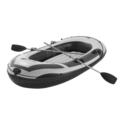
Avon SEASPORT DELUXE JET 320 User manual

WARNING
CAREFULLY READ THIS MANUAL BEFORE OPERATING YOUR
BOAT.
THIS OWNER’S MANUAL IS IN TWO VOLUMES THAT MUST BE
KEPT TOGETHER.
NOTICE:
THE OWNER'S MANUAL IS IN TWO VOLUMES:
- VOLUME 1
DEALS WITH OPERATING PRECAUTIONS AND SAFETY
RECOMMENDATIONS THAT MUST BE OBSERVED.
- VOLUME 2
DEALS WITH TECHNICAL SPECIFICATIONS AND ASSEMBLY
PROCEDURE OF THE BOAT AND ITS EQUIPMENT.
VOLUME 2
TECHNICAL SPECIFICATIONS - ASSEMBLY PROCEDURE
SEASPORT DELUXE JET
320 & 400
NOTICE TO
CUSTOMER
Your boat should have been inspected by an
authorised agent prior to delivery.
Confirmation of this inspection will be found at the
back of this manual with the agents stamp, date and
signature.
CONTENTS
Page Page
Table of technical specification. 2 Operating your boat 26
Electrical diagrams 5 Transportation 30
Assembly procedure 7 Storage 30
Check on unpacking. 7 Maintenance. 33
Inflation system. 8 Emergency procedures. 44
Pressure 9 Troubleshooting. 46
Standard equipment. 11 Certificate of Pre-Delivery Inspection. 47
Pre-operational checks. 25 Declaration of Conformity. X
1

TABLE OF TECHNICAL SPECIFICATIONS
S
SEASPORT DELUXE JET 320 400
Dimensions
Overall length (metres) 3.20 4.00
(feet/inches) 10' 5" 13' 1"
Overall beam (metres) 1.70 1.85
(feet/inches) 5’ 7" 6' 1"
Inside beam (metres) 0.79 0.95
(feet/inches) 2’ 7" 3' 1"
Boat weight (kg)
(lbs) 250
550
300
660
Buoyancy tube (metres) 0.44 0.45
Diameter (feet/inches) 17.3" 17. 7"
Capacity
Airtight compartments 4 4
Persons 36
Weight (1) (kg) 360 490
(Lbs) 800 1080
Inboard data
Yamaha 2 stroke
Single stage axial flow jet pump propulsion with reverse gate.
Fuel capacity (Litre)
(Gal.Imp.)
40
8.8
60
13.2
Maximum power (kW)
(hp)
60.0
80
60.0
80
Certification
(Directive 94/25/CE) C C
All dimensions indicated have a tolerance of +/- 3% The weights indicated for the boats do not include
any extras.
(1) The maximum payload has been calculated according to ISO standards. Operating at or near
maximum payload is only advised in calm water and at reduced speeds.
KEY: To Plan views of Seasport D.L.. Jet 320 and 400, see pages 3 - 4.
1. Navigation light, bow.
2. Bow step.
3. Bow cleat.
4. Bow seat cushion.
5. Bow locker.
6. Davit lifting point, bow.
7. Forward grab handle.
8. Deck.
9. Console / engine cover.
10. Console switches.
11. Warning label.
12. Deck drains
13. Aft grab handles.
14. Avon logo.
15. Davit lifting points stern.
16. Stern cleat.
17. Ski ring.
18. Stern platform.
19. Bow fairleads.
20. Buoyancy tube.
21. Rubstrake.
22. Deck light.
23. Forward seat.
24. Fuel filler cap.
25. Engine.
26. Instrument dials.
27. Tilt helm.
28. Choke knob
29. Steering wheel.
30. Throttle.
31. Bench seat upholstery
32. Jet pump.
33. Navigation lighting mast.
2

GENERAL SPECIFICATIONS
SEASPORT JET 320
Key on page 2
3
19
20
21
9
1
3
17
22
8
10
2
4
5
6
7
23
24
16
11
12
25
26
18
27
28
30
13
14
15
29
31
32
33

GENERAL SPECIFICATIONS
SEASPORT JET 400
Key on page 2
4
19
20
21
9
1
3
17
22
8
10
2
4
5
6
7
23
24
16
11
12
25
26
18
27
28
30
13
14
15
29
31
32
33

Standard wiring for the Seasport Jet 320 and 400
1. Battery.
2. Master switch.
3. Starter relay.
4. Fuse.
5. Rectifier regulator.
6. Ignition coil.
7. Thermal switch.
8. CDI unit.
9. Electrical box.
10. CDI magneto.
11. Starter motor.
12. Multi-function meter.
13. Oil sender.
14. Fuel sender.
15. Speed sensor.
16. Bow Nav.Light
17. Courtesy light
18. Fuel earth.
19. Bilge pump
20. Blower
21. Courtesy light
22. Bilge switch fuse
23. Stop switch.
24. Start switch.
25. Microswitch start
protect
26. Kill switch.
27. Blower switch
28. Nav.Light switch
29. Courtesy switch
30. Main breaker
31. Courtesy light
32. Stern nav. Light
33. Anode.
34. Oil sender relay
35. Fuel gauge.
36. Oil warning light.
G. GREEN.
B. BLACK.
P. PURPLE.
Y. YELLOW.
O. ORANGE.
Br. BROWN.
R. RED.
Bl. BLUE.
Pk. PINK.
W. WHITE
5

ASSEMBLY PROCEDURE
We recommend that you follow the specific order of the assembly procedure. Proceed step by
step and refer to the corresponding pages.
PROCEDURE PAGE SECTION
1. Inventory the elements composing your boat,
and learn how to recognise them. 6CHECK ON UNPACKING
2. Activate valves into inflating position. 7 INFLATION SYSTEM
3. Slightly inflate the main buoyancy tube. 9INFLATION
4. Finish inflation of the boat to the correct pressure. 8-9 INFLATION / PRESSURE
5. Learn to use the standard equipment. 10 STANDARD EQUIPMENT
CHECK ON UNPACKING
CAUTION
DO NOT USE A SHARP TOOL
The pack must contain a fully fitted out hull, deck and buoyancy tube, plus:
SEASPORT JET 320 400
Repair kit
Owner’s manual *
Foot pump
Spark plug ( x2 )
Water hose connector
Master switch keys
Lanyard
Fuel cap key
* 2 volumes
You can equip your boat with many optional accessories (davit lifting equipment etc.). Ask your
dealer to advise you.
NOTE:
IF YOU WISH TO LIFT YOUR BOAT USING DAVITS CONTACT YOUR
DEALER FOR THE CORRECT LIFTING EQUIPMENT AND FITTING
INSTRUCTIONS
WARNING
USE ONLY AVON AUTHORISED DAVIT LIFTING EQUIPMENT.
SEVERE INJURY OR DEATH COULD OCCUR FROM USING EQUIPMENT
PRODUCED TO AN INADEQUATE SPECIFICATION FOR THE BOAT.
6

INFLATION SYSTEM
THE SEMI-RECESSED VALVES
Inflation position Deflation position
Valve closed, the inner button springs
upwards.
Valve open, the inner button pushes down
and twists to the left.
NOTICE:ALWAYS REPLACE VALVE CAP AFTER INFLATING OR DEFLATING
THE FOOT PUMP
1 Hose end piece.
2 Hose base.
3 Outlet for inflation up to
150 mb / 2.2 PSI
4 Outlet for inflation over
150 mb / 2.2 PSI
•Activate all valves into the inflation position.
•Fit the hose (item 2) to the outlet in the foot pump (item 3).
•To inflate your boat properly, the bottom side of the foot-pump must rest on a flat surface.
•Insert the hose end piece (item 1) into the inflation valve.
•Pump evenly to inflate rapidly.
WARNING
DO NOT USE A COMPRESSOR OR A BOTTLE OF COMPRESSED AIR
7
14
2
3

PRESSURE
The correct pressure for the buoyancy tube is 170 mb/2.5 PSI.
We recommend that you purchase a pressure indicator from your Dealer. This will permit a quick
and efficient control of the pressure during inflation. Without a pressure indicator, stop inflating
when the foot-pump gets difficult to operate, and the boat is «hard » (you should not be able to
bend the cone ends).
Ambient temperature of air and water Ambient temperature tubes’ internal pressure
have an effect on the boat’s internal +1°C / +1,8°F +4 mb / 0,06 PSI
pressure -1°C / -1,8°F -4 mb / 0,06 PSI
Therefore, it is important to anticipate:
Because of temperature variations (especially when this variation is important between the
beginning and the end of the day, in hot areas) check and adjust the pressure in the inflated
compartments by inflating or deflating. Be sure that pressure remains within the recommended
zone, between 130 mb/2.0 PSI and 200 mb/3,0 PSI.
RISK OF UNDERPRESSURE
EXAMPLE: Your boat is in direct sunlight on the beach (temperature =50°C/122°F) at
recommended pressure (170 mb/2.5 PSI). After putting it in the colder water (temperature
=20°C/68°F), the internal temperature and pressure of the tubes will both drop (up to 85 mb/1.8
PSI) and YOU WILL HAVE TO INFLATE AGAIN until you regain the lost pressure due to the
difference in temperatures. Therefore a loss of pressure at the end of the day, when ambient
temperature drops, is perfectly normal.
NOTE :
Proper inflation is critical to the performance of the boat. It is the pressure in
the tubes that gives your boat the necessary rigidity to perform well. Under-
inflation causes improper flexing of the tubes which will result in stress and
chafe
RISK OF OVERPRESSURE
EXAMPLE: Your boat is inflated to the recommended pressure (170 mb/2.5 PSI) at the
beginning of the day (low ambient temperature =10°C/50°F). Later in the day, your boat is in direct
sunlight on the beach or on a yacht’s deck (temperature =50°C/122°F). Internal temperature of all
inflated compartments can then increase and reach up to 70°C/158°F (especially for dark-coloured
tubes). The consequence will be a doubling of previous pressure (340 mb/5.0 PSI). YOU WILL
THEN HAVE TO DEFLATE until you reach the recommended pressure.
WARNING
WHEN YOUR BOAT IS OVER INFLATED, PRESSURE BECOMES TOO
STRONG FOR THE INFLATABLE STRUCTURE, AND COULD CAUSE A
BREAK IN THE FABRIC ASSEMBLY
IN CASE OF OVERPRESSURE
SEMI-RECESSED VALVE :
Deflate by pressing the spring loaded
button.
8

TO INFLATE THE MAIN BUOYANCY TUBE
•Inflate to a maximum pressure of 200 mb, (refer to PRESSURE section) making sure that
each compartment is equal.
NEVER COMPLETELY INFLATE
A COMPARTMENT TO FULL
PRESSURE IF OTHER
COMPARTMENTS ARE
TOTALLY DEFLATED
100 %
0 %0%
50 %50 %50 %
100 %100 % 100 %
•Correctly inflated, the internal bulkheads (item 1) are not visible.
•When inflation is over, fit the valve caps tight (clockwise).
NOTE : A slight air-leak before screwing the valve caps is normal.
ONLY THE VALVE CAPS CAN ENSURE FINAL AIR TIGHTNESS.
1. The inflation valve for the stern starboard
buancy tube compartment is located in
the engine compartment. Raise the
console lid for access.
9
1
1

STANDARD EQUIPMENT
GENERAL INFORMATION
Record your H.I.N. and engine numbers in the spaces provided, to assist you in
ordering spare parts from your Avon/Yamaha dealer. Also record and keep these I.D.
numbers in a separate place in case your boat is stolen.
Engine Serial Number
The Engine serial number is stamped on a
plate attached to the forward end of the
engine.
1. Hull Identification Number (H.I.N.)
The H.I.N. is located at the stern of the boat.
FUEL REQUIREMENTS
NOTE : Petrol (Gasoline) - Use regular unleaded petrol (gasoline).
WARNING
PETROL (GASOLINE) AND ITS VAPOURS ARE HIGHLY
FLAMMABLE AND EXPLOSIVE
•Do not smoke when refuelling, and keep away from sparks, flames, or other
sources of ignition.
•Stop the engine before refuelling.
•Refuel in a well-ventilated area.
•Open the fuel tank filler cap, and slowly add fuel to the fuel tank. Be careful not to
spill fuel or overfill the tank.
•To remove the fuel tank filler cap, turn it anti-clockwise.
•Take care not to spill petrol (gasoline). If petrol (gasoline) spills, wipe up
immediately with dry rags. Always properly dispose of petrol-soaked rags.
10
M ODEL
YAM AHA
CODE SERIAL No.
1

•Avoid overfilling the fuel tank. Stop filling when the fuel level just reaches the
bottom of the fuel filler tube. Do not fill up the filler tube because fuel expands as it
warms up and could overflow.
•Fuel tank capacity in the Seasport D.L. Jet 320 is 40 Litres (8.8 gal.imp.) (10.6
gal.US). Fuel tank capacity in the Seasport D.L. Jet 400 is 60 Litres (13 gal.imp.)
(16.2 gal.US).
•If you should swallow some petrol (gasoline), inhale a lot of petrol (gasoline)
vapour, or get petrol (gasoline) in your eyes, seek immediate medical attention.
•If any petrol (gasoline) spills onto your skin, immediately wash with soap and
water. Change clothing if petrol (gasoline) is spilt on it.
1. Fuel filler cap.
2. Use key to help tighten or
release. Keep the key on the
ignition key ring.
•Tighten the filler cap securely after refuelling.
CAUTION
Be careful when refuelling. Avoid getting water or other
contaminants in the fuel tank.
Contaminated fuel can cause poor running or engine damage.
WARNING
PETROL (GASOLINE) AND ITS VAPOURS ARE HIGHLY
FLAMMABLE AND EXPLOSIVE
OIL INJECTION SYSTEM
NOTE :
Engine Oil: YAMALUBE, TWO STROKE MOTOR OIL FOR MARINE
If YAMALUBE is not available, another 2-stroke engine oil with a BIA-
certified TC-W3 rating may be used.
•This engine uses Yamaha's oil injection system, which provides lubrication by
ensuring the proper oil ratio for all operating conditions. No fuel pre-mixing is
necessary (except during break-in). Simply pour petrol (gasoline) into the fuel tank
and oil into the oil tank.
11
2
1

CAUTION
Do not allow the oil tank to empty completely. If the tank
empties the oil injection pump must be bled to ensure proper
oil flow, otherwise engine damage may occur. See page 39.
ENGINE STOP SWITCHES
1. Stop button.
2. Emergency stop switch.
3. Lock plate.
4. Lanyard.
5. Always attach the engine
stop switch lanyard to your
left wrist BEFORE starting
the engine.
6. To prevent accidental
starting of the engine,
always remove the lock-
plate from the stop switch
when the engine is not
running.
•These switches have the following functions: one is to stop the engine normally by
pressing button 1 on the console; the other is to stop the engine if you fall off, or in
case of an emergency, when lock-plate 3 attached to the lanyard is pulled from the
switch 2.
•When the button on the switch is pushed, without removing the lock-plate the
ignition circuit opens and stops the engine immediately.
•Should the lock-plate be removed for any reason, the engine will stop.
12
1. Oil filler cap.
2. oil level is indicated on the
multi-function meter located
on the console.
3. The oil tank capacity is: 3.8
litres (0.83 gal. Imp.) (1.0 gal.
U.S.)
1
1
2
4
5
3
6

WARNING
Once the engine has stopped, you have NO STEERING
CONTROL over the boat.
STARTER SWITCH
1 Start button.
2 Console.
•To start the engine, push the top button 1 on the console 2.
NOTE :
It is not possible to start the engine with the lock-plate removed
from the engine stop switch.
It is not possible to start the engine with the throttle lever in gear.
Note that the master switch and fuel tap must also be switched on.
CONTROLS - THROTTLE LEVER
•To start the boat's engine and to activate the throttle for engine warm-up, the
handle must be in the neutral position. Neutral can be found by rotating the handle
(by grasping the knob or stem) until the handle locks in a vertical position and can
not be rotated in either direction.
1. Knob.
2. Umbrella.
3. Handle.
4. Button.
5. Push and hold button in.
6. Pull umbrella up.
7. Advance handle
13
1
2
1
2
3
4
5
6
7

WARNING
•TAKE EXTREME CARE.
•Some forward thrust will be produced when the engine is running
even when in neutral, so make sure there are no obstacles or
people in front or behind you.
•Before starting the engine, always check the operation of the
throttle lever. It should move smoothly through its full range of
operation.
CONTROLS - SHIFT LEVER
1. Neutral position.
2. Forward shift position.
3. Reverse shift position.
4. Throttle.
•Throttle warm up. Push in the button with your left hand while grasping the umbrella and
knob with your right hand and pull the umbrella up towards the knob. While still holding
the button and umbrella, advance the handle forward or rearward to put the control in
warm-up throttle mode. Once in this mode, the button and the umbrella can be released
and throttle can be adjusted by simply moving the control handle away from the neutral
position to increase throttle and towards the neutral position to decrease throttle.
Returning the handle to the neutral position will disengage throttle warm up.
•Use "Reverse" for slow speed manoeuvring only. It is useful when launching the boat from
a trailer, or when it is necessary to back up out of tight spots where you cannot turn around.
WARNING
•Make sure there are no obstacles or people behind you before
shifting into reverse.
•Do not touch the reverse gate whilst it is being shifted. You could
be pinched.
•Shifting to REVERSE will not slow down or stop the boat from
higher speed. Reverse is for slow speed manoeuvring only.
1. Make sure the reverse gate of
the jet pump goes down to its
stopper position when the
control shift lever is placed in
REVERSE position.
2. Also make sure the reverse gate
of the jet pump goes up to its
stopper position when the
control shift lever is placed in
FORWARD position.
14
1
2
30°
30°
1
2 3
4 4

CHOKE CONTROL & SWITCHES
1. Choke knob.
2. Navigation light
switch.
3. Courtesy Light switch.
4. Blower switch, for
engine compartment
ventilation.
5. Bilge pump switch
6. Warning label.
•Pulling the choke knob supplies a rich fuel-air mixture required to start the engine.
•Pushing switches down at the front turns them on.
•The engine compartment blower must be turned on for at least four minutes
before starting the engine.
•The three switches are also circuit breakers and will trip off if a fault occurs in the
electrical system. If the trip needs to be reset then the electrical problem must be
rectified before further use.
WARNING
BEFORE STARTING ENGINE, CHECK THE ENGINE
COMPARTMENT BILGE FOR PETROL (GASOLINE) OR
VAPOURS AND OPERATE BLOWER FOR 4 MINUTES. VERIFY
BLOWER OPERATION.
RUN BLOWER WHEN VESSEL IS OPERATING BELOW
CRUISING SPEED.
NOTE : Refer to Starting the engine on pages 27 for proper operation.
15
3
2
1
4
6
5

FUEL TAP
1 Fuel tap, "ON" position.
•The fuel tap is located on the starboard side inside the engine compartment and
supplies fuel from the tank to the carburettor.
•The fuel tap has two positions;
OFF - With the knob in this position, fuel does not flow. Always turn the knob to
this position when the engine is not running.
ON - This is the position for normal running.
RETRACTABLE CLEATS
•There are retractable cleats at the bow and stern. The bow cleat pulls up and can be
pushed down when not in use. The stern cleats operate in a similar way except
they are spring loaded and pop up when the button is depressed.
1. Bow cleat.
2. Pull up and push down.
3. Bow step.
16
1
1
2
3
FU EL ON
FU EL OFF

1. Stern cleat.
2. Press button for cleat to move up.
3. Push cleat down when not in use.
LIFTING, TOWING & SKIING
1. Stern Davit lifting strong point.
2. Ski hook.
17
2
1
3
1
1
2

MULTI FUNCTION METER ( 400 DL JET )
1 Engine oil level meter.
2 Hour meter.
3 Speedometer display.
4 Warning light (oil / overheat /
fuel).
5 Fuel level meter.
1 Overheat warning display
(refer to page 21 overheat
warning device)
1. Oil tank full.
2. Fuel tank full.
1. Oil warning blinking.
(top off the oil level
immediately)
1. Fuel warning.
(Refuel)
18
1 2 3 4 5
1
21
1
1

CONSOLE - ENGINE COVER
•For access to the engine, emergency bilge pump, fuses, oil tank and fuel tank, raise
the console/engine cover. The securing latch is located at the front of the console.
1 Latch.
2 Console / Engine cover.
•The latch is located at the front of the console/engine cover.
•The console/engine cover is supported by a gas strut.
CAUTION
Ensure the console - engine cover is firmly secured before
using the boat.
BATTERY
1. Battery.
2. Positive (+) terminal.
3. Negative (-) terminal.
4. Battery securing strap.
5. Bench seat stowage
compartment.
•The battery is located in the bench seat stowage compartment. Always check the
battery condition and the electrolyte level before use.
WARNING
The battery must always be fully charged and in good
condition, loss of battery power may leave you stranded.
Never operate the boat if the battery has difficulty starting the
engine or shows any signs of decreased power.
19
1
2
3
4
5
1
2

OVERHEAT WARNING SYSTEM
1. Jet intake.
2. Impeller
1. Engine.
2. Drive shaft.
3. Water cooling hose.
•The engine has an over-heat warning device. If the engine starts to overheat,
engine speed will be limited to about 3,000 revs/min.
•If this happens, beach the boat and check for a blockage at the water intake to the
jet pump. Open the engine cover and check for a blockage in the water cooling
hose.
WARNING
BE SURE THE ENGINE IS SHUT OFF AND THE LOCK PLATE IS
REMOVED FROM THE STOP SWITCH BEFORE ATTEMTING TO
REMOVE DEBRIS FROM THE JET INTAKE. THE IMPELLER CAN
CAUSE INJURY.
CAUTION
If you cannot locate the cause of the overheating, return to the
nearest port at low speed.
Consult your nearest dealer.
Continuing to operate at higher speeds could result in serious
engine damage.
FIRE EXTINGUISHER
•Always ensure that a fire extinguisher is aboard and in proper condition. See the
manufacturers instructions to determine the proper indication of condition.
•Provision has been made for installing a fire extinguisher, in a recessed
moulding, below the front of the bench seat, , refer to Stowage, page 22.
NOTE : A fire extinguisher is not standard equipment with this boat. If
you do not have one, it is recommended that an appropriate
fire extinguisher is carried for use in emergencies.
20
1 2
1
3
2
This manual suits for next models
1
Table of contents
Other Avon Boat manuals