Famco ECONOMIZER BREATHE SMARTER User manual

Installation Manual Essentials 120213
BREATHE SMARTER
Simple, Reliable,
On Demand, Better
Indoor Air Quality
and
Economizing
www.famcoiaq.com
FAMCO IAQ
ECONOMIZER
Patent Pending
TM
PATENT PENDING

Installation Manual Essentials 120213
1
OVERVIEW - TYPICAL INSTALLATION SEQUENCE
IF YOU HAVE NOT INSTALLED A FAMCO IAQ ECONOIZER BEFORE, IT IS RECOMMENDED THAT
YOU READ ALL INSTRUCTIONS IN THIS MANUAL BEFORE STARTING.
1) Determine if existing system allows for proper installation of the IAQ Economizer:
a. See “SYSTEM REQUIREMENTS” on the next page.
b. Access to existing ductwork, and ability to install components as recommended?
The damper box should be installed ALL return air to flows through the damper
box on its way to the blower. This may require some ductwork reconfiguration.
2) Determine installation location for outside air intake, outdoor air thermostat, Damper
Box, and Logic Box.
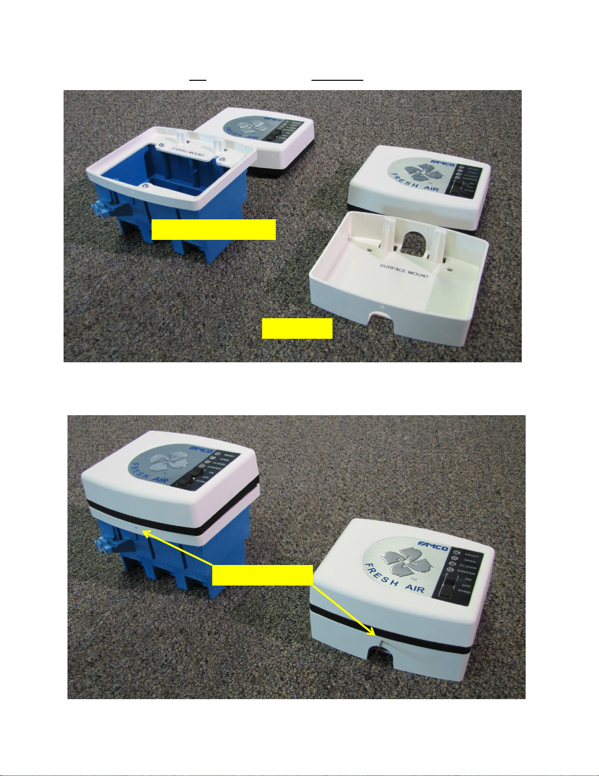
a. There are two options for Logic Box installation: 3-gang/flush wall, or surface
mount. The surface mount option is provided for retrofit garage and mechanical
room installs where wall cavity wire pulls may not be possible or would be cost
prohibitive.
3) Determine if the existing HVAC system is functioning properly before beginning
installation.
4) Place damper box in the location where it will be installed.
5) Install outside air intake louver, transition, and connect flex duct to transition.
6) Connecting the flex to the appropriate port on the damper box.
7) Cut, Adjust length, and connect return duct to the damper box.
8) Connect damper cable to the damper box quick connect plug and run the cable to the
Logic Box install location.
9) Install the transformer and run the Power Cable to the install Logic Box Location.
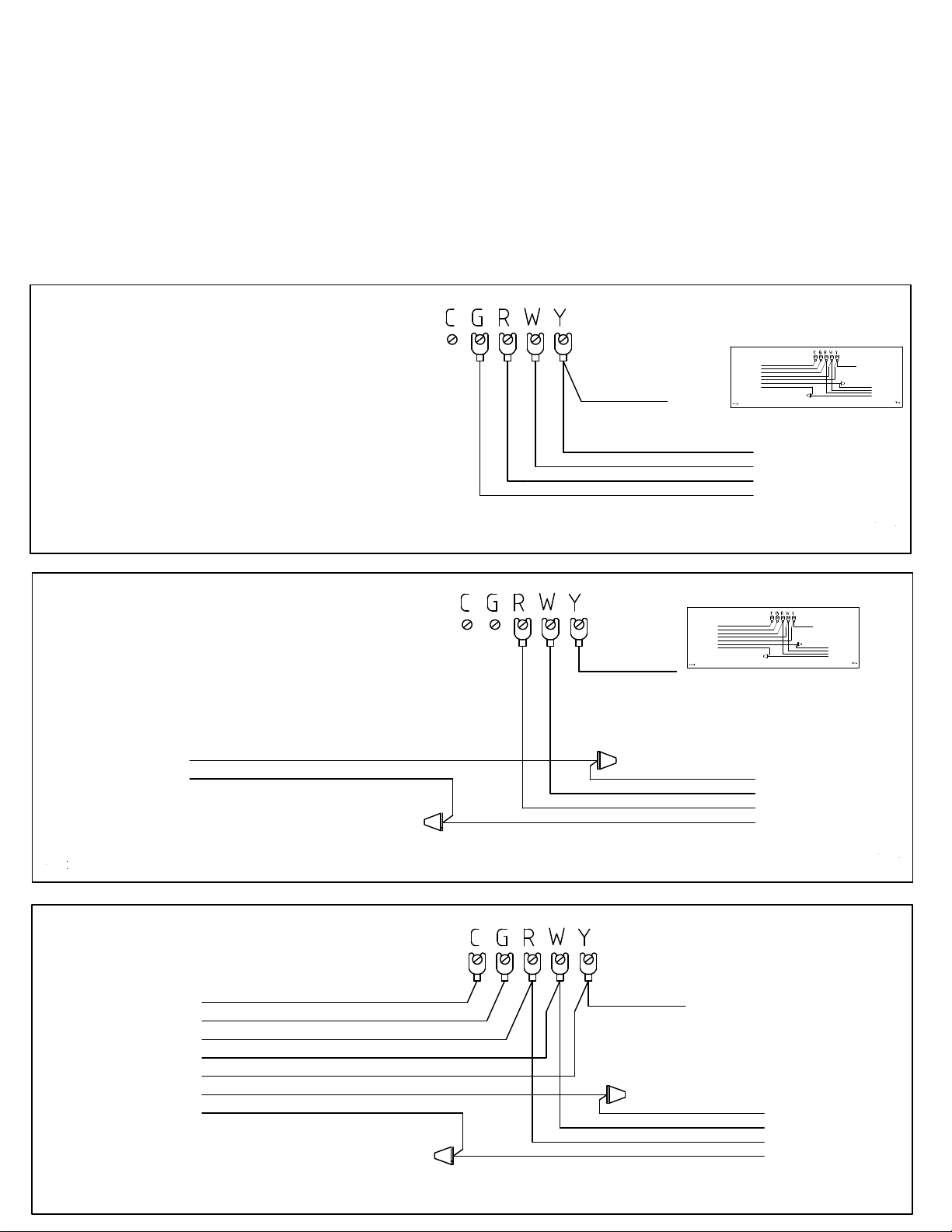
10) Terminate the Furnace Cable to the existing furnace board and run the other end to the
Logic Box install location.
11) Install the outdoor air thermostat, terminate wire to the thermostat, and run the other
end to the Logic Box install location.
12) Connect all cables to their appropriate terminations on the Logic Box, and secure logic
box.
13) Turn on power to IAQ Economizer and HVAC system.
14) Test system for proper operation. You should observe the physical operation of the
damper at least once to insure it is stroking properly. You can do this by holding open
the butterfly damper and watching damper movement and seal.

Installation Manual Essentials 120213
2
BEFORE BEGINNING INSTALLATION
SYSTEM REQUIREMENTS
The IAQ Economizer was designed for use with constant speed fans installed on systems using
conventional thermostats. The IAQ Economizer can be installed on systems with proprietary or
communicating thermostats, but these installations will not have the full range of features
available to a conventional system.
Systems with a modulating fan have several options for installation. Visit
famcoiaq.com/MANUALS for wiring with modulating fans.
Visit famcoiaq.com/MANUALS for wiring FAMCO for use with heat pumps.
Verify that the existing system is operating properly. Initiate a call for cooling and observe
operation of the blower and condensing unit, and delivery of cooled air.
INSTALLATION
IMPORTANT: Turn off the HVAC system at the breaker box before beginning installation.
Do not use the existing furnace transformer to power the IAQ Economizer. The furnace
transformer is not sized to support proper economizer operation.
Straightness of ductwork matters. Avoid sharp bends in ductwork. Watch out for flex duct
that may become misshapen if required to turn close to the connection to the damper box.
Proper operation requires that at a minimum an equal amount of air passes over the
evaporator coil as in normal return air operation. Insure that air volume is not negatively
impacted by the installation of damper box. It is the installers’ responsibility to insure the
appropriate volume of air is available. Poor installation may adversely affect available air
volume and could damage HVAC system.
Do not allow the thermostat “Fan call”to run the blower fan below the mechanical cooling
speed as this will result in poor performance. In the case of free-cooling, more air is better.

Installation Manual Essentials 120213
3
TRANSFORMER
(LOCATE WHERE CONVENIENT
–NOT IN ATTIC)
EXTERIOR WALL (NORTH SIDE PREFERRED,
WEST OK, ROOF OPTION AVAILABLE EAST OR
SOUTH NOT RECOMMENDED)
OUTSIDE AIR INTAKE LOUVER/TRANSITION
RESIDENTIAL (SINGLE BOX) SYSTEM –COMPONENT LOCATION (FIGURE 1)
LOGIC BOX –CAN BE INSTALLED ANYWHERE INDOORS,
BUT SHOULD BE LOCATED IN A PLACE WHERE IT CAN
BE EASILY ACCESSED BY OCCUPANT.
OUTSIDE AIR
TEMPERATURE
THERMOSTAT
EXISTING
FURNACE
BOARD
OUTSIDE AIR FLEX
DUCTWORK ADDED
(NOT PROVIDED IN KIT)
IMPORTANT:
MINIMIZING TURNS AND BENDS IN DUCTWORK IS
CRITICAL TO SYSTEM PERFORMANCE.
THE OUTSIDE AIR TEMPERATURE THERMOSTAT MUST
BE LOCATED IN A COOL OUTSIDE LOCATION
REPRESENTING OUTDOOR AIR TEMP, NOT EXPOSED
TO DIRECT SUNLIGHT OR ADJACENT TO ATTIC
SPACES, AND ACCESSIBLE FOR ADJUSTMENT BY
OCCUPANT. NORTHERN EXPOSURE IS
PREFERRED.
DIAGRAM SHOWS GENERAL LOCATION OF SYSTEM COMPONENTS. THE IDEAL INSTALLATION WILL VARY BY HOUSE.

Installation Manual Essentials 120213
4
INSTALLING THE OUTSIDE AIR INTAKE LOUVER AND DAMPER BOX
Identify the main return duct at the point after any secondary returns feed into the main
return. This is where the damper box will be installed. (Install the damper box to allow for the
shortest and straightest duct runs possible.)
Move the Damper Box to the installation location. Be careful when moving the damper box to
the attic as to not damage the damper or damper actuator.
Install the gable vent and transition, (outside air intake,) on the North side of the building. If
this is not possible, install the gable vent on the West or East side. Installing the gable vent on
the South side may significantly degrade system performance. If installation on the North,
West or East side are not possible, FAMCO recommends using a rooftop intake. Preferred
orientation for roof vents is the same as for gable vents.
Connect a flex duct from the intake transition to the FRESH AIR port on the Damper Box.
Cut the main return duct in a location that will allow re-connection to the damper box. (The
damper box will replace a section of duct, so the duct may need to be shortened to prevent the
restriction of return air.)
Connect the return duct to the RETURN port on the damper box.
Connect the duct leading to the fan to the FAN port on the damper box.
Install the butterfly damper and make it is oriented so gravity pulls it closed when not held
open by airflow.
Identify the damper cable. (Has a large gray and orange connector that connects to the damper
box connector.) Connected to the Damper Box quick connect plug. Run the other end of the
damper cable to the location where the Logic Box will be installed in the conditioned space.
INSTALLING THE OUTDOOR AIR THERMOSTAT
IDEAL - Install on North side of structure: Shielded from all direct sunlight. Not adjacent to
attic space. Accessible by occupant and for service.
OK - Install on West side of structure. Shielded from all direct sunlight, (would require a
ventilated enclosure.) Not adjacent to attic space.

Installation Manual Essentials 120213
5
DO NOT install the outdoor thermostat inside the ductwork or louver, on the South or East
side of the home, or where it will be exposed to direct sunlight or other sources of heat such as
adjacent to an attic wall or near an air conditioning condensing unit.
1) Connect one conductor of OSAT Cable to the thermostat Red common terminal.
2) Connect the other conductor to the Blue (close on cooling) terminal.
3) The uninsulated wire is a drain wire. It should not come into contact with anything at the
outdoor thermostat end. Cut it short enough so that the outer jacket of the OSA cable
covers the shield.
4) It is recommended that thermostat be set at 70 - 72 degrees.
5) Run the other end of the OSAT Cable back to the location where the Logic Box will be
installed.
INSTALLING THE 24VAC TRANSFORMER
Install the 24VAC transformer near enough to the Logic Box to reach the Logic Box with power
cable. The unit runs on 24VAC only. Other sources of power will damage the unit. DO NOT
power the unit with power from the AC unit. (The furnace transformer will not have sufficient
capacity to provide for the IAQ Economizer.)
Provide 120 VAC power to the appropriate side of the transformer.
Connect the Power Cable to the 24 VAC side of the transformer. Transformer common
connects to the Power Cable Black wire.
Run the Power Cable to the location where the Logic Box will be installed.
CONNECTING THE FURNACE CABLE
Connect the Furnace Cable to the existing furnace board using the diagram shown in FIGURE 2.
Run the Furnace Cable to the location where the Logic Box will be installed. If running the fan
on high speed is not possible with the furnace cable installed as depicted, visit our website and
review the “Alternate Furnace Cable” installation diagram and instructions.
INSTALLING THE LOGIC BOX (You do not need to open the Logic Box for installation.) Install
Logic Box in a place where occupants can easily access for daily operation. Two Logic Box
attachment plates are provided: One for 3-gang box/flush mounting, the second for surface
mounting. Only one is used per install.

Installation Manual Essentials 120213
6
All terminal plugs on the Logic Box can be removed from the Logic Box board. Use a screw
driver to gently pry them loose. Terminate wires before reconnecting plugs to the board.
Install mounting plate to 3-gang box or wall.
Bring cables pulled earlier; Damper Cable, Power Cable, Furnace Cable, Outdoor thermostat
(OSAT) Cable through the mounting plate.
Connect the Damper Cable to the Logic Box termination labeled "Damper Cable."
Connect the Furnace Cable to the relay logic box termination labeled "Furnace Cable."
Connect the OSAT Cable to the 3 conductor plug provided with the kit. The thermostat wires
are connected to the bottom two terminations on the plug. The top terminal is provided as a
drain. It should be connected to the uninsulated shield conductor, 3rd conductor of the OSAT
wire. IMPORTANT: Verify that the wires of the OSAT cable are terminated correctly before
plugging it into the Logic Box.
Connect the Power Cable to the Logic Box.
IMPORTANT: There is one auxiliary connection that is required for the Logic Box to function.
This is the LIMIT termination. See FIGURE 4. FAMCO recommends that appropriate safety
switches be installed for the climate at the installation site. Recommended limits include low
temperature and humidity limits. Selection and installation of appropriate limits is the
responsibility of the system installer.
It is at the contractors’ discretion if they choose to “Jump-out” this connection to enable the
system to function without safeties installed. To jump-out safeties install a wire connecting
terminal 1 to terminal 2. See Figure 4.
FAMCO recommends the installation of an indoor low limit with all installations. This addition
greatly expands both the functionality and energy savings delivered by the system. Figure 4
also shows the installation of an indoor low limit thermostat.
Attach the Logic Box to the Mounting Plate using the set screw and wrench provided.

Installation Manual Essentials 120213
7
INSTALLING THE FURNACE CABLE (FIGURE 2)
Furnace Board
Before
ef
ore
Furnace Board After (Step 1 & 2)
2)
efore
Furnace Board After
< To Logic Box
To Thermostat >
Condensing Unit
Yellow
Yellow
Green
Green
White
Red
Condensing Unit
Yellow
Green
Red
White
To Thermostat >
Condensing Unit
Yellow
Yellow
Green
Green
Red
White
White
Red
Blue
Brown
Orange
< To Logic Box
To Thermostat >
Step 1
Step 2
Before
Furnace Cable
Furnace Cable
(FIGURE 3)

Installation Manual Essentials 120213
8
STEP 3: Plug the other end of the furnace cable into the logic box connection marked “FURNACE.”

Installation Manual Essentials 120213
9
3-GANG OR SURFACE MOUNT OPTIONS (FIGURE 3)
3-GANG/FLUSH
SURFACE
E
SET SCREW

Installation Manual Essentials 120213
10
TESTING
Testing Damper
CAUTION: (If it is below 45 degrees F outside and the furnace has been running, it is
recommended that the furnace be turned off and allowed to cool before introducing outdoor
air into the system.)
Turn on the HVAC system at the breaker box.
Turn the Logic Box System switch to the “OFF” position. The Yellow damper “Closed” LED
should be lit. If the Red “Damper” LED is lit this means that the damper was detected in the
wrong position, or the damper cable is unplugged. If the Yellow light did not come on stop
here to troubleshoot the system.
If the Yellow “Closed” LED is lit go ahead and set the HVAC system for a call for cooling. Verify
that both the blower and condenser are functioning properly. Turn the IAQ Economizer
System switch to the “ON” position.
Depending on the outdoor temperature and outdoor thermostat setting, the Yellow light may
go out and the red light may come on if the system is opening the dampers. If the yellow light
stayed on, use the Override, OVRD, switch to initiate an air introduction. If the Yellow light
went out before you switched the OVRD switch, and the Red light lit, wait 90 seconds. The
Green light should light indicating that the dampers are open. If the Red light stays lit stop
here to troubleshoot the system.
The Red “Damper” LED should come on within 5 seconds as an indication that dampers are
opening. The dampers take about 90 seconds to fully open. Once open, the Green “Open” LED
should light indicating that dampers have been detected in the appropriate Open or
Economizing position. As soon as dampers are properly detected the blower fan should start
and the condensing unit should stop. At this time you are bringing outdoor air into the
indoors.
Turning OFF the IAQ Economizer should cause the damper to close, which in turn should re-
light the Yellow (Closed) light.
Observation of the proper operation of the damper box and butterfly damper should be
observed visually at least once during testing.
Testing the Outside Air Thermostat
Make sure the System switch is in the “ON” position. Set the existing indoor thermostat for
cooling. Make sure the Logic Box Override switch is in the “OFF” position. If the Red LED is lit

Installation Manual Essentials 120213
11
the dampers are already stroking. This will depend on the outdoor setting and the outdoor
temperature.
Depending on the present outdoor temperature turning the outdoor thermostat will either
open or close the dampers. Turn the setting dial to actuate the system for both open and
closed conditions. Verify status on LEDs. Once this is verified go ahead and set the outdoor
thermostat to the setting desired by the occupant. FAMCO recommends 70 –72 degrees.
Unless you are installing optional equipment, you are done with installation.
IMPORTANT: If you are installing optional devices these devices should also be tested for
proper operation. Testing these devices can be done in a manner similar to testing the outside
air thermostat. ALWAYS follow equipment manufacturers testing and operation instructions.
Information about installing auxiliary devices can be found below. Install diagrams can be
downloaded at famcoiaq.com/manuals.
TROUBLESHOOTING
If the system is powered, and does not open the damper box as expected, there are four items
that should be checked:
1) IAQ Economizer switch may be OFF.
2) LIMIT Switch is OPEN or no jumper is installed.
3) Outdoor thermostat setting requirements have not been met. (Not cool enough
outside.)
4) There is no call for cooling. Either the existing HVAC system thermostat must be calling
for cooling, or an Indoor Low Limit thermostat installed with the economizer must be
calling for cooling.
The OVRD switch overrides both the outdoor thermostat and the call for cooling. If the system
does not function properly while using the OVRD switch the likely cause is the LIMIT not being
installed or satisfied.
If the damper indicator light is showing a RED –DAMPER light after 90 seconds this means that
the damper is either 1) Not moving, or 2) Not being detected in the proper position. If the RED
–DAMPER light does not go out, visually inspect the damper box to see if it is operating
properly. If the damper is stroking, but not being detected in the proper condition you will
need to remove the cover, (bulge in insulation on side of box,) and adjust the clamp on the
damper shaft. After adjustment, test operation several times to make sure OPEN and CLOSED
lights are indicating properly.

Installation Manual Essentials 120213
12
All components of the IAQ Economizer are tested before shipping.

Installation Manual Essentials 120213
13
Recommended Optional Control Terminations
IMPORTANT: APPROPRIATE LIMIT DEVICES SHOULD BE INSTALLED FOR ALL SYSTEMS SO THAT OUTDOOR AIR IS NOT
INTRODUCED DURING UNDESIREABLE OUTDOOR CONDITIONS. CAN BE USED FOR HIGH OR LOW TEMP, DEW POINT,
HUMIDITY, CO2, CO OR ANY OTHER LIMITING INPUT DEVICE. DEVICE WILL DEPEND ON INSTALL LOCATION CLIMATE.
24VAC POWER FOR AUXILIARY DEVICES CAN BE TAKEN FROM THE LOGIC BOX "PWR OUT". NOT SHOWN CONNECTED
ON DRAWING FOR CLARITY. MULTIPLE LIMITING DEVICES SHOULD BE INSTALLED IN SERIES.
TOTAL TRANSFORMER CAPACITY IS 50VA. LOGIC BOX + TRANSFORMER TYPICALLY CONSUME LESS THAN 20VA.
DEVICES USING "PWR OUT" CANNOT EXCEED 50VA TOTAL TRANSFORMER CAPACITY.
EXTERNAL DEVICES PROVIDING A POWERED SIGNAL TO THE LOGIC BOX REQUIRE AN ISOLATION RELAY.
OUTDOOR LIMIT DEVICE
(NORMALLY CLOSED - DRY CONTACT)
72
INDOOR LOW LIMIT
(ADDITIONAL, TYPICAL THERMOSTAT, (NOT PROVIDED) -
NOT THE EXISTING FURNACE THERMOSTAT)
SOME STAT MODELS
WILL NOT REQUIRE 'C'
THE INDOOR LOW LIMIT OPTION ALLOWS OWNERS TO USE ONE SETPOINT FOR
MORE EXPENSIVE COMPRESSOR BASED COOLING, WHILE HAVING A COOLER
SETTING FOR LOWER COST VENTILATION COOLING WHEN AVAILABLE.
VISIT FAMCOIAQ.COM/MANUALS FOR ADDITIONAL CONTROL OPTIONS
R
Y
R
C
RELAY -
24 VAC COIL
MECHANICAL STATS
DO NOT REQUIRE
RELAY. SWITCH T2
JUMPER
FIGURE 4

Installation Manual Essentials 120213
14
FAMCO IAQ Economizer
OPTIONAL FUNCTIONS (INSTALLATION DIAGRAMS ARE AVAILABLE AT
famcoiaq.com/manuals
Installation of optional devices has been kept separate from the main portion of the install
directions because optional functions are numerous, and will vary from install to install.
LIMIT - Any number of limits may be used with the system. Limits are used to LIMIT the
operation of the system to conditions deemed safe by the limits installed. If for instance a limit
is installed for outside air temperature, and that limit is set to OPEN below an outside
temperature of 40 degrees F; the system will not allow an introduction during conditions at or
below 40 degrees F. This includes attempted outdoor air introductions using the override and
introductions that occur automatically. The one exception being starts initiated using AUX
START 1.
Typical Uses: Outdoor air low or high limit, outdoor humidity or dew point limit.
Multiple devices need to be wired in series.
T2 - Input used to allow a different setpoint to call for economizer operation other than the
existing HVAC thermostat. Typical use is to allow a lower ventilation cooling setpoint than the
mechanical cooling setpoint. Using T2 requires that the outside air temperature requirements
be met for ventilation cooling, and that LIMITs also be met before an air introduction is
allowed.
Typical Use: Along with providing a separate ventilation cooling setpoint, T2 can also be used
for additional timers when the occupant prefers that overrides are only executed during times
when the outdoor air temperature is conducive for cooling.
Multiple devices need to be wired in parallel.
AUX START 1 - Will initiate air introduction regardless of all other system configurations. If this
input is made the system will open dampers and attempt to start the fan regardless of ALL
other conditions.
Typical Use: CO or other Alarm to start system.

Installation Manual Essentials 120213
15
IMPORTANT: Using AUX START1 may cause damage to the HVAC system, the home, or items in
the home if an alarm signal initiates an air introduction during conditions when installed limits
would prevent operation.
Systems using the AUX START 1 should test operation in accordance with input device
recommendations.
Multiple devices need to be wired in parallel.
AUX START 2 - Used to start the system for ventilation. Auxiliary overrides, timers, CO2 and
VOC sensors should be wired to AUX START 2. Devices wired to AUX START 2 do not require
outdoor temperature thermostat conditions be met, but do require LIMIT conditions be met
before an outdoor air introduction is allowed.
Multiple devices need to be wired in parallel.
POWER - Power simply provides 24 VAC that can be used to power other control devices used
with the system.
The top terminal is 24VAC, the bottom terminal is neutral.
Typical Use: Power CO2 controller, CO Alarm, or relays used to complete optional control
circuits.
Multiple devices need to be wired in parallel. If multiple devices are to be wired, contact
FAMCO for maximum amperage recommendations.
HRV - Power is supplied to this terminal any time the system is initiating an outdoor air
introduction.
Typical Use: To power a relay to STOP an HRV or ERV during ventilation cooling cycles, to
indicate system operation at a remote location, to use as a start signal to a secondary
ventilation cooling device such as a powered exhaust or to run supply and exhaust fans for a
garage economizer.
Multiple devices need to be wired in parallel.

Installation Manual Essentials 120213
16
AUXILLIARY CONNECTIONS (FIGURE 5)
LIMIT
T2
EXT START 2
PWR OUT
HRV INTRUPT
EXT START 1
13 NOT USED
12 COMMON
11 ECON SIG
10 COMMON
9 24VAC
8
7
6
5
4
3
2
1

Installation Manual Essentials 120213
17
SEQUENCE OF OPERATIONS (FIGURE 6)
OUTSIDE TEMP < SETTING
EXT START 1 = ON
LIMIT CONDITIONS MET
SYSTEM ON
STAT CALLING
EXT START 2 = ON
DAMPER CORRECT
OPEN DAMPER(S)
FAN = ON
COMPRESSOR = ON
YES
YES
YES
YES
YES
YES
YES
NON-ECON SUPPORTED COOL CALL?
YES
ERROR INDICATION
NO
DAMPER POSITION
YES
CONTINUOUS
T2 CALLING
STAT CALLING non-ECON
OPERATION
OVRD (LOGIC BOX)
COMPRESSOR INTERRUPT
YES
YES
Table of contents
Popular Thermostat manuals by other brands

Cypress Envirosystems
Cypress Envirosystems WPT Series quick start guide

Aube Technologies
Aube Technologies TH131 user guide

DELTA DORE
DELTA DORE PACK TYBOX 5000 installation instructions

Trotec
Trotec BN35 operating manual

Honeywell
Honeywell VisionPRO Series user guide

Melchioni
Melchioni MK932 instruction manual