Fantasia line FA-1 User manual

1FA-1 LED Strobe Trigger Instruction Manual 20170613
Fantasea Line
FA-1 LED Strobe Trigger (Cat. No. 6551)
Instruction Manual
The FA-1 LED Strobe Trigger triggers underwater strobes and
flashes to fire in sync with the camera using fiber optic cables.
Using the LED Strobe Trigger eliminates the need for the
camera built-in flash to fire, thereby extending camera battery
life and allowing for longer shooting sessions. Eliminating the
camera built-in flash also keeps the camera from heating up,
resulting with less condensation in humid conditions. The LED
Strobe Trigger’s super quick recycle time allows for rapid
shooting and triggering of the strobes without having to wait
for the camera built-in flash to charge.
COMPATIBILITY
The FA-1 LED Strobe Trigger can be connected to any camera featuring a hot-shoe connection. It can be
installed inside any camera housing offering sufficient space, anywhere inside the housing, for the main
unit to be placed. For LED Strobe Triggers specially designed for Fantasea housings, please visit the
Fantasea website –www.fantasea.com
The FA-1 LED Strobe Trigger is capable of triggering most underwater strobes available in the market. Note
that when using the LED Strobe Trigger, strobe output is controlled manually only.
SPECIFICATIONS
LED type: Ultra bright white LED
LED ports: 2
Voltage: 3.7 V
Power consumption: 5 milliwatt
Battery: 110mAh Lithium Polymer battery
Charging time: 1.5 hours
Flash capacity: 10,000 (when fully charged)
Battery life: Up to 72 hours (when fully charged)
Auto power-off time: 3 hours
Dimensions: 40.5 x 45 x 13 mm / 1.6 x 1.77 x
0.51 inch
Weight: 16.8 g / 0.51 oz
Included in package: LED Strobe Trigger main
unit, LED cable, Hot-shoe cable, Spongy LED
trigger ports, Velcro sticker, Rubber band and
USB cable
INCLUDED IN PACKAGE
1
2
3
5
4
7
6

2FA-1 LED Strobe Trigger Instruction Manual 20170613
The following descriptions refer to INCLUDED IN PACKAGE items drawings on the previous page:
1. LED Strobe Trigger main unit
2. Spongy LED trigger ports
3. USB cable
4. Hot-shoe cable
5. Rubber Band
6. Velcro sticker
7. LED cable
IDENTIFICATION OF MAIN UNIT PARTS
1. Indicator light
2. Hot-shoe cable port
3. 5V DC port
4. Power switch
5. LED cable port
INSTRUCTIONS FOR USE
1. Charging the FA-1 LED Strobe Trigger main unit:
a. Connect the micro-USB end of the USB cable to the main unit’s 5V DC port (Fig.1).
b. Connect the other end of the USB cable to a USB port or USB charger (Fig.2).
c. The unit should start charging and the indicator light should start flashing green (Fig.3).
d. When charging is complete, the indicator light stops flashing and remains green.
5
2
1
3
5
Fig.1
Fig.2
Fig.3

3FA-1 LED Strobe Trigger Instruction Manual 20170613
2. FA-1 LED Strobe Trigger Installation
a. Connect the LED cable to the main unit using the LED cable port (Fig.4). Make sure you’re
connecting the LED cable to the correct port and note that accidently connecting the LED cable
to the Hot-shoe port will result with failure to operate the LED Strobe Trigger.
b. Connect the Hot-shoe cable to the main unit using the Hot-shoe cable port (Fig.5). Make sure
you’re connecting the Hot-shoe cable to the correct port and note that accidently connecting
the Hot-shoe cable to the LED Cable port will result with failure to operate the LED Strobe
Trigger.
c. Install the hot-shoe connector featured at the end of the hot-shoe cable on the camera by
gently sliding the hot-shoe connector all the way through the hot-shoe mount featured on top
of the camera (Fig.6). Note that if a protective cover is installed on the camera hot-shoe
mount, it should be removed prior to installing the hot-shoe connector of the LED Strobe
Trigger.
d. Test the LED Strobe Trigger:
i. Turn the camera on. Note that there’s no need to set the camera flash mode, as the LED
Strobe Trigger is activated whenever an image is captured, even if camera flash mode is set
to “Flash Off”.
ii. Turn the LED Strobe Trigger on by sliding the power switch featured on the main unit to the
“ON” position. The indicator light should start flashing green (if fully charged).
iii. Capture an image by fully depressing the camera shutter release while carefully observing
the two LED’s featured at the end of the LED cable. Depressing the shutter release should
flash both LED’s (Fig.7 on the following page). If depressing the camera shutter release and
capturing an image doesn’t flash the LED’s, reinstall the LED Strobe Trigger following the
steps above or refer to section 4 - “Troubleshooting”.
Fig.5
Fig.4
Fig.6

4FA-1 LED Strobe Trigger Instruction Manual 20170613
iv. Test the LED Strobe
Trigger with the strobe.
Make sure the strobe is
properly charged prior
to performing the test.
Turn the strobe on and
set it to “Manual”
operation mode. Turn
the camera and the LED
Strobe Trigger on. Place
the strobe in front of the
camera so it faces the
camera lens. Place one
of the LED’s featured at
the end of the LED cable
in front of the strobe slave sensor. Capture an image by fully depressing the camera shutter
release. The light emitted by the LED should trigger the strobe to fire in sync with the
camera, resulting with an overexposed image, in which the output of the strobe is visible. If
the strobe isn’t triggered by the LED, refer to section 4 – “Troubleshooting”.
e. If your housing features built-in LED trigger ports, proceed to step e below. If your housing
doesn’t feature dedicated LED trigger ports, the spongy LED trigger ports included in the
package should be installed inside the housing:
i. Peel the protective film off the sticker side of the spongy LED trigger ports and stick them
inside the housing, against the fiber optic cable ports facing the camera built-in flash. Make
sure that the center of the spongy LED trigger ports is positioned exactly opposite to the
center of the fiber optic cable ports to allow for the light emitted by the LED’s to be
transmitted through the fiber optic cables (Fig.8).
ii. If your housing features a transparent window against the camera built-in flash instead of
fiber optic cable ports, it is best to attach the fiber optic cables to the transparent window
Fig.8
Housing
Fiber Optic Cable
Fiber Optic Cable Port
Spongy LED Trigger Port
LED
Fig.7

5FA-1 LED Strobe Trigger Instruction Manual 20170613
prior to installing the spongy LED trigger ports in order to allow for perfect alignment of the
spongy LED trigger ports with the fiber optic cables.
f. Attach the LED cable port to the housing LED trigger ports (spongy or built-in) by inserting
the LED’s featured at the end of the cable into the housing LED trigger ports and gently
pushing them all the way in (Fig.9).
g. Install the camera inside the housing as described in the housing instruction manual. Make
sure that LED Strobe Trigger components (main unit, LED cable and Hot-Shoe cable) don’t
interfere with proper camera installation by moving them away from the camera slot.
h. Once the camera is installed inside the housing, secure the main unit inside the housing by
attaching it to one of the housing side panels using the Velcro sticker included (Fig.10).
When selecting where to secure the main unit, make sure that LED Strobe Trigger
components –including the main unit and the various cables –don’t interfere with camera
operation or housing watertight seal. Although the main unit can be removed from the
housing by detaching the Velcro, it’s best to select a location that allows leaving the LED
Strobe Trigger inside the housing even when the camera is removed. The top side panel, if
featuring sufficient space, is usually the best choice.
i. Once all components have been installed inside the housing, use the rubber band to bundle
excess length of the LED cable in order to ensure it doesn’t interfere with camera operation
or housing seal.
Fig.9
Fig.10

6FA-1 LED Strobe Trigger Instruction Manual 20170613
j. When closing and locking the housing, make sure that no cables get caught in the way, as
this might interfere with a proper housing seal. Upon closing the housing and prior to
diving with it, submerge it in a shallow tub of water or rinse tank. Carefully look at the
housing to make sure no bubbles are escaping from it, no water is entering and the
moisture alarm (if installed inside the housing) doesn’t beep.
k. Once the system is completely installed, make sure that the light emitted by the LED’s of the
LED Strobe Trigger doesn’t escape the LED trigger ports and reflect on your lens port. Turn
on the camera and LED Strobe Trigger. Cover the housing lens port with its port cover (or
any other cover that completely blocks light from entering the lens port) and capture an
image. View the image you’ve captured and make sure that it’s a completely dark one with
no reflections.
3. FA-1 LED Strobe Trigger Operation
a. Setup the entire underwater camera system, including camera, housing, LED Strobe Trigger,
strobes and fiber optic cables installation.
b. Note that the strobes should be set to manual operation mode and their output level should
be manually controlled.
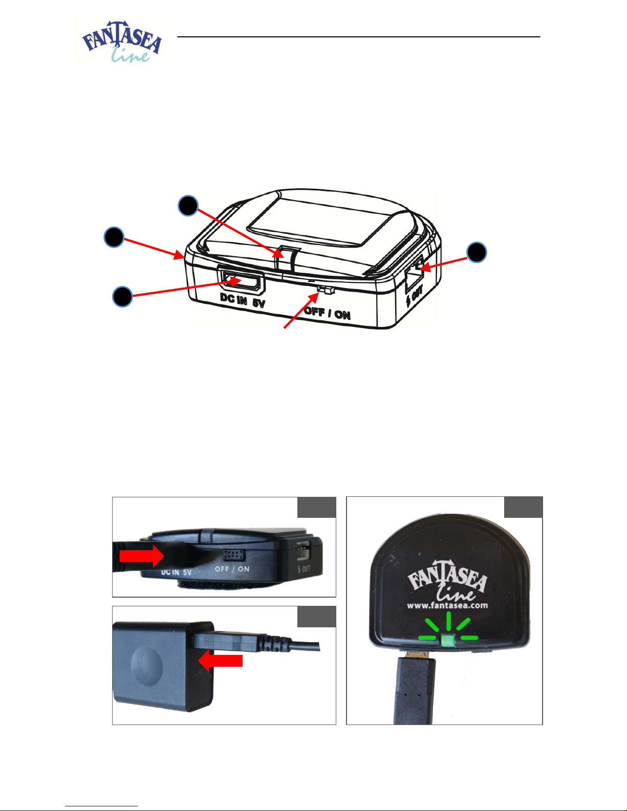
c. Turn the LED Strobe Trigger on by sliding the power switch featured on the main unit to the
“ON” position. The indicator light should start flashing once in 2 seconds.
d. The color of the flashing indicator light indicates battery charge level:
i. Green (100%-50% power)
ii. Yellow (50-25% power)
iii. Red (25-1% power)
e. Close the housing as described in the housing instruction manual. When closing and locking
the housing, make sure that no cables get caught in the way, as this might interfere with a
proper housing seal. Refer to section 2, step h for shallow water testing of the housing seal
prior to the dive.
f. Capturing images by fully depressing the housing shutter release control will flash both
LED’s featured at the end of the LED cable inside the housing. The light emitted by the LED’s
is transmitted to the slave sensor of the strobes through the fiber optic cables, thus
triggering them to fire in sync with the camera. In case of failure to trigger the strobes to fire
in sync with the camera, please refer to section 4 - “Troubleshooting”.
g. Note that there’s no need to set the camera flash mode, as the LED Strobe Trigger is
activated whenever an image is captured, even if camera flash mode is set to “Flash Off”.
h. During the dive, preventing the strobes from firing can be carried out by either turning the
strobes off or disconnecting the fiber optic cables from the strobes or camera housing.
Disabling the flash through camera menus will have no effect in this case, as the LED Strobe
Trigger is activated whenever an image is captured regardless of the selected camera flash
mode.
i. Turn the LED Strobe Trigger off when not in use by sliding the power switch featured on the
main unit to the “OFF” position.
j. Note that if the LED Strobe Trigger isn’t operated for a period of 3 hours, it will
automatically enter standby mode and the indicator light will turn off. The LED Strobe
Trigger can be turned back on by capturing an image with the camera (thus flashing the
LED’s) or by sliding the power switch to “OFF” and then back to “ON” again.
k. To prevent the strobe from overheating as a result of being frequently triggered, please
refer to the strobe instruction manual for guidelines and precautions.

7FA-1 LED Strobe Trigger Instruction Manual 20170613
4. Troubleshooting
In case of failure to trigger the strobes to fire in sync with the camera using the LED Strobe Trigger,
please make sure that:
a. All components of the LED Strobe Trigger have been properly installed, as described in
section 2 –“FA-1 LED Strobe Trigger Installation”.
b. The main unit of the LED Strobe Trigger has been properly charged.
c. The Hot-shoe cable is connected to the Hot-shoe cable port and the LED cable is connected
to the LED cable port. Note that if the LED’s featured at the end of the LED cable are shining
continuously, this usually has to do with the cables connected to the wrong ports.
d. The spongy LED trigger ports (if installed) are perfectly aligned with the fiber optic cable
ports and the windows behind the fiber optic cable ports are clean. This can be tested
similarly to as described in section 2, step c, only this time closely observing the LED’s from
out of the housing, through the fiber optic cable ports or openings. If properly installed and
the windows behind the ports are clear, you should be able to clearly see the LED’s flashing
through the fiber optic cable ports whenever an image is captured with the camera.
e. The fiber optic cables made use of are of high quality and sensitive enough to transmit the
light emitted by the LED’s. Note that with some strobes, multi-core fiber optic cables are
required for sufficient light transmission. This can be tested by removing the fiber optic
cable from the strobe slave sensor and instead, placing one of the LED’s featured at the end
of the LED cable in front of the slave sensor. If the strobe is now triggered by the LED when
capturing an image with the camera, the fiber optic cable should most likely be replaced
with a more sensitive one.
f. Camera shutter speed is sufficiently low for triggering the strobe (usually 1/160 or lower).
g. The strobe is fully charged and set to “Manual” operation mode.
h. The strobe slave sensor is operative and intact. This can be verified by attempting to trigger
the strobe by the camera flash. Turn the strobe on and set it to “Manual” operation mode.
Turn the camera on and set the camera flash to “forced flash”. Position the camera flash in
front of the strobe slave sensor and capture an image. If the strobe isn’t triggered by the
camera flash, contact the strobe manufacturer for support.
CARE & MAINTENANCE
1. Please use the utmost care and do not use excessive force when assembling and disassembling the
different accessories, in order not cause any damage to the products.
2. Keep the FA-1 LED Strobe Trigger away from water. After the dive and prior to opening the housing,
make sure to dry it well in order to prevent water from dripping on the LED Strobe Trigger once the
housing has been opened.
3. Keep the FA-1 LED Strobe Trigger away from extreme high temperatures, as under direct sunlight,
since it might damage the product.
4. Do not clean the FA-1 LED Strobe Trigger with any chemical solvents or other materials, which
might cause damage to the product.
5. When storing the FA-1 LED Strobe Trigger and during transportation, make sure that it is properly
protected in order to prevent any damage to the product.
6. Do not store the FA-1 LED Strobe Trigger in presence of chemicals, solvents or fuels.
7. To prolong battery life of the FA-1 LED Strobe Trigger, it is important to fully charge the main unit
prior to long periods of storage. Recharge the main unit every 3-6 months during storage in order
to avoid battery over-drain.

8FA-1 LED Strobe Trigger Instruction Manual 20170613
FANTASEA PRODUCT CONSUMER LIMITED WARRANTY
“Fantasea” warrants this Fantasea Line branded product against defects in materials and workmanship
under reasonable use for a period of ONE (1) YEAR, (two years, where required by law as determined by
the origin of the authorized dealer). This warranty is effective from the date of retail purchase from
Fantasea or an authorized Fantasea dealer, by the original end-user purchaser (“Warranty Period”). This
warranty does not cover any commercial use of the product. If a product defect arises and a valid claim
is received within the Warranty Period, at its option, Fantasea, or its authorized service facilities will
either (1) repair the product defect at no charge, (2) exchange the product with a product that is new or
which has been manufactured from new or serviceable used parts and is at least functionally equivalent
to the original product. The warranty will not extend beyond the original warranty period. Your
Fantasea Product should be registered within 30 days of purchase. You must keep the proof of purchase
which indicates the date on which the purchase was made; as you may be required to show proof of
purchase if you need warranty service. The following conditions apply:
1. This warranty extends to the original purchaser only. It is not assignable or transferable. 2. The
warranty does not cover damage resulting from misuse, abuse, negligence, or accidents. Proper
maintenance of the Product is the responsibility of the owner. 3. The warranty does not cover damage
directly or indirectly resulting from the use of unauthorized replacement parts or service performed by
unauthorized facilities. 4. This warranty does not cover any damage to any other product used in
conjunction with the Fantasea product, including cameras and lenses, and resulting from any defect in
the product materials or workmanship. 5. The cost of sending the product back to Fantasea or its
authorized service facilities is the responsibility of the customer. 6. The warranty does not cover any
incidental damages resulting from any defects in the product. This expressly includes any travel
reimbursements or any other costs associated with the purchaser’s optional use of the product. The
conditions of this warranty are expressly in lieu of all other expressed warranties, including the payment
of consequential or incidental damages for the breach of any warranty. Please register your product on
line at this URL: http://www.fantasea.com/registration.
www.fantasea.comor visit our websiteinfo@fantasea.comFor further information, please contact us at
Table of contents