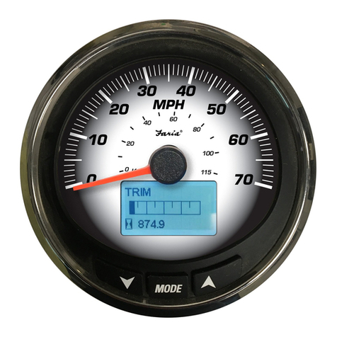
Faria Beede MG3000 Instruction Manual

MG3000 - Speedometer
Installation / User Manual
www.FariaBeede.com
25.0
FT
DEPTH
IS0399
Rev. A ecn 10591 6/2017

Table of Contents
Release Information
Date Rev. ecn Program VersionDescription
June 2017 A 10591 PGF368 v EFirst Release
IMPORTANT: This guide was written for the 4 inch MG3000 speedometer with the latest Software version:
referenced below. Gauges with other software versions may have features not documented in this guide. To view
the gauge software version, refer to Software Version page 7.
Installation ........................................................................................................................................ 2
Panel Thickness ............................................................................................................................. 2
Hole Sizes....................................................................................................................................... 2
Attaching the Back Clamp .............................................................................................................. 2
Wiring Diagram ................................................................................................................................. 3
Power On........................................................................................................................................... 4
System Setup ................................................................................................................................. 4
Select Number of Tanks.................................................................................................................. 4
Normal Mode..................................................................................................................................... 4
Edit Menu Options............................................................................................................................ 5
System............................................................................................................................................ 5
Initialization ................................................................................................................................ 5
Audio.......................................................................................................................................... 5
Warning Audio (ON or OFF) ................................................................................................. 6
Setting Saved Audio Setting ................................................................................................. 6
All Sounds ............................................................................................................................ 6
Performing A Master Reset ........................................................................................................ 7
Software Version........................................................................................................................ 7
Data Sources .................................................................................................................................. 7
Tanks.......................................................................................................................................... 8
Depth ......................................................................................................................................... 8
Depth Warnings .............................................................................................................................. 8
Shallow Water............................................................................................................................ 8
Deep Water................................................................................................................................ 9
Keel Offset ................................................................................................................................. 9
Display Settings ............................................................................................................................ 10
Setting Number of Data Pages ................................................................................................ 10
Screen Setup ........................................................................................................................... 10
NO DATA.................................................................................................................................. 10
1

Installation
Description
The MG3000 instruments use a “plug and play” networking technology and is connected directly to the MG3000
tachometer.
The MG3000 speedometer is controlled by a three-button keypad. The buttons and a brief description of their uses:
• UP and DOWN: Used to scroll through available pages in Normal Mode or options within the system menus.
• MODE: Used to access system menus, a short push of less than one second exits a menu and a long push of
greater than one second makes a selection.
Panel Thickness
Instruments can be mounted in panels up to 1” (13 mm) thick and in panels up to 1.5” with trimming the back clamp.
Hole Sizes
IMPORTANT: Check space behind panel to be sure there is adequate clearance for instruments exists before drilling
panel.
Cut a 3 3/8” (85 mm) diameter hole in the panel for the 4” instruments.
Cut a 4 3/8” (112 mm) diameter hole in the panel for the 5” instruments.
Attaching The Back Clamp
Insert instrument into the panel cutout. Slide back clamp on gauge, place washer and finger tighten the nut (6-8 inch
pounds). Repeat for second stud.
1
2
3
25.0
FT
Depth
2

Tachometer
Multifunction Gauge
Speedometer
4- pin connector
12- pin connector
Pin A 7.7 vDC Faria Bus (+)
Pin B Faria Bus A
Pin C Faria Bus B
Pin D Ground
Pin 1 7.7 vDC (Faria Bus +)
Pin 2 Faria Bus A
Pin 3 Faria Bus B
Pin 4 Ground
Pin 5 12vDC Ignition
Pin 6 Analog Input 1
Pin 7 Analog Input 2
Pin 8 Analog Input 3
Pin 9 • NMEA B+
• J1939 12 vDC Ignition (jumper to pin 5)
Pin 10 • NMEA Ground
• J1939 Shield
Pin 11 • NMEA CAN Hi (+)
• J1939 CAN Hi (+)
Pin 12 • NMEA CAN Low (-)
• J1939 CAN Low (-)
Ignition
Ignition
J1939 Ignition Jumper
Analog Input 1
Analog Input 2
Analog Input 3
Analog Input 1 (optional)
Analog Input 2 (optional)
Analog Input 3 (optional)
Faria Bus
4- pin connector
Pin A 7.7 vDC Faria Bus (+)
Pin B Faria Bus A
Pin C Faria Bus B
Pin D Ground
Faria Bus
(To other gauges)
12- pin connector
Pin 1 7.7 vDC (Faria Bus +)
Pin 2 Faria Bus A
Pin 3 Faria Bus B
Pin 4 Ground
Pin 5 12 vDC Ignition
Pin 6 Analog Input (optional)
Pin 7 Analog Input (optional)
Pin 8 Analog Input (optional)
Pin 9 7.7 vDC (Faria Bus +)
Pin 10 Faria Bus A
Pin 11 Faria Bus B
Pin 12 Ground
Pitot connection
for Speed. (Optional)
6
5
4
3
2
1
7
8
9
10
11
12
1
2
3
6
5
4
6
5
4
3
2
1
7
8
9
10
11
12
1
2
3
6
5
4
Wire Jacket
Information from the ECU
6- pin connector (GPS)
Pin 1 N/C
Pin 2 N/C
Pin 3 NMEA 0183 (+)
Pin 4 NMEA 0183 (-)
Pin 5 N/C
Pin 6 N/C
6- pin connector (Depth)
Pin 1 N/C
Pin 2 N/C
Pin 3 Depth Signal (+)
Pin 4 Depth Signal (-)
Pin 5 N/C
Pin 6 N/C
Jumper required for the J1939
harness and is Not required
for the NMEA2000 harnesses.
Wiring Diagram
3

Power On
Turn the ignition key to the ON position. It is not required to start the engine for system
initialization. The power on sequence for the tachometer and speedometer consists of a
Self-Test, which occurs at every power on event. The Self-Test process consists of the
following steps:
1) If initialization is complete, the LCD will display SELF TEST. All of the lights in the
MG3000 blink. Dial lights first, LCD back lights and then warning lights.
2) All system pointers will return to the zero position.
3) All system pointers will sweep to full scale.
4) All system pointers will go to current value.
When the Self-Test is complete, if the gauge displays data then the system initialization has
already been completed. To customize the data displayed in the LCD go to Display Settings on
page 10.
Otherwise, if this is the first time you have powered on your MG3000 speedometer, you will be
prompted to System Setup. Complete the required system setup.
System Setup (Speedometer)
The speedometer initialization is required for the installed system to operate correctly. In order
to complete the initialization process the user must select the set the number of tanks in the
system. If you do not know that the system is monitoring tanks set the number of tanks to zero
(0). This setting will be set up at the factory.
The following sections describe the steps necessary to complete the speedometer initialization.
Select Number of Tanks
The first part of the initialization is selecting the tanks connected in the system. (This feature
may not be available in all speedometers.
1) Use the UP or DOWN buttons to select the number of tanks to be used. If you do not
know how many tanks are available use 0.
2) Press and hold the MODE button to save the tank selection. The LCD screen displays,
SETTING SAVED!, along with an audible beep.
3) When numbers of tanks is complete, the initialization is complete and the display will
read, BASIC INITIALIZATION COMPLETE!. The MG3000 issues an audible beep.
APP SELF TEST
SOFTWRE REV
PGFXXX X
BUILD X##
Normal Mode
When the initialization for the speedometer is complete the MG3000 speedometer is ready for
use. The LCD display will show the Normal mode. MG3000 configurations may vary, not all
data will be available in the Normal mode (the LCD displays NO DATA). Use the DISPLAY
menu to turn off those data pages (page10).
Use the UP or DOWN buttons to scroll through the Normal mode default display pages.
PRESS OR
SET NUMBER OF
TANKS
0
DEPTH
25.0
FT
GPS SPEED
25.0
MPH
AIR TEMP WATER TEMP
75.1
˚F
65.0
˚F
T1: BALLAST1
50
GAL
T1: BALLAST1
50
%
T2: BALLAST2
50
GAL
T2: BALLAST2
50
%
T3: BALLAST3
50
GAL
T3: BALLAST3
50
%
(Not all data is available with all MG3000 packages)
4

System
Use the SYSTEM edit menu to initialize the speedometer, control the Audio settings, perform a
Master Reset and to view the current software version for the speedometer. Follow the steps
below to view the SYSTEM edit menu options.
1) From the NORMAL mode, press the MODE button once.
2) Use the UP and/or DOWN buttons to select SYSTEM.
3) Press and hold the MODE button to make the selection.
Initialization
If the MG3000 speedometer has not been initialized previously, when the power is first applied
the speedometer will automatically start up into the INITIALIZATION mode.
If you wish to initialize the speedometer after the initial set up was completed, enter the SYSTEM
menu (page 5) then:
1) Use the UP or DOWN buttons to select INITIALIZE.
2) Press and hold the MODE button to make selection.
3) Use the UP or DOWN buttons to select YES to initialize or NO to return to the EDIT
menu.
4) Press and hold the MODE button to make selection.
To complete the initialization process, set the number of tanks in the system.
The LCD display will show BASIC INITIALIZATION COMPLETE!. The MG3000 issues an
audible beep.
Audio
The Audio menu is used to turn on or off the buzzer for warnings. To make changes to the
system audio enter the SYSTEM menu (page 5) and then:
Note: The audio setting ALL, should NOT be used to turn OFF warnings.
1) Use the UP or DOWN buttons to select AUDIO options.
2) Press and hold the MODE button to make the selection.
3) Use the UP or DOWN buttons to select the desired menu.
4) Press and hold the MODE button to make the selection.
Edit Menu Options
While in the Normal mode, pressing the MODE button once will show the Speedometer Edit
Menu Options. The Speedometer Edit Menu Options are:
• SYSTEM: is used to make global speedometer; initialization of the speedometer,
changes for Audio, Master Reset and view the Software version.
• DATA SOURCES: is used to select the data sources for Tanks and Depth.
• DEPTH WARNINGS: Sets the warning depths for Shallow and Deep water depths
• DISPLAY: is used to edit the data pages that are shown in Normal Mode.
Note: Although the manual may identify a particular function as being part of the MG3000
architecture individual functions may not be available for your installation. Check with your
engine and boat manufacturer for function availability.
SYSTEM
DATA SOURCES
DEPTH WARN
INITIALIZE
AUDIO
MASTER RESET
AUDIO
MASTER RESET
SOFTWARE
Warning Audio Setting (ON or OFF)
Use WARNING BEEP to turn the buzzer ON or OFF while a warning is occurring in the
Speedometer. To change the setting enter the SYSTEM menu (page 5) then enter the AUDIO
menu:
IMPORTANT: Turning off the WARNING BEEP is NOT recommended.
1) Use the UP or DOWN buttons to select the WARNING BEEP.
2) Press and hold the MODE button to enter the selection.
3) When prompted, select the WARNING BEEP AUDIO STATUS. Use ON to have the
speedometer beep when a warning occurs, or OFF to turn off the beep and return to the
AUDIO options menu.
4) Press and hold the MODE button to save the setting. The LCD screen displays
SETTING SAVED! and the MG3000 issues an audible beep.
Setting Saved Audio Setting
Use SET SAVED to turn the buzzer ON or OFF after a setting is saved in the speedometer.
To change the setting enter the SYSTEM menu (page 5), then:
1) Use the UP or DOWN buttons to select the SET SAVED.
2) Press and hold the MODE button to enter the selection.
3) When prompted, select the SETTING SAVED AUDIO STATUS. Use ON to have the
speedometer beeps when saving a setting, or OFF to turn off the beep and return to the
AUDIO options menu.
4) Press and hold the MODE button to save the setting. The LCD screen displays
SETTING SAVED! and the MG3000 issues an audible beep.
Button Press Audio Setting
Use BUTTON PRESS to turn the buzzer on or off whenever a button is pressed on the
speedometer.
Enter the SYSTEM menu (page 5) then:
1) Use the UP or DOWN buttons to select the BUTTON PRESS.
2) Press and hold the MODE button to enter the selection.
3) When prompted, select the BUTTON PRESS AUDIO STATUS. Use ON to have the
speedometer beep after every button press, or OFF to turn off the beep and return to the
AUDIO options menu.
4) Press and hold the MODE button to save the setting. The LCD screen displays,
SETTING SAVED!, and the MG3000 issues an audible beep.
All Sounds
Use ALL to turn the buzzer ON or OFF for ALL the Audio menu options.
Note: The audio setting ALL, should NOT be used to turn OFF warnings.
Enter the SYSTEM menu (page 5) then:
1) Use the UP or DOWN buttons to select the ALL
2) Press and hold the MODE button to enter the selection.
3) When prompted, select the ALL BEEPS AUDIO STATUS. Use ON to have the
speedometer beep for all audio feedback or OFF to turn off the beep and return to the
AUDIO options menu.
4) Press and hold the MODE button to save the setting. The LCD screen displays
SETTING SAVED! and the MG3000 issues an audible beep.
5

Audio
The Audio menu is used to turn on or off the buzzer for warnings. To make changes to the
system audio enter the SYSTEM menu (page 5) and then:
Note: The audio setting ALL, should NOT be used to turn OFF warnings.
1) Use the UP or DOWN buttons to select AUDIO options.
2) Press and hold the MODE button to make the selection.
3) Use the UP or DOWN buttons to select the desired menu.
4) Press and hold the MODE button to make the selection.
Warning Audio Setting (ON or OFF)
Use WARNING BEEP to turn the buzzer ON or OFF while a warning is occurring in the
Speedometer. To change the setting enter the SYSTEM menu (page 5) then enter the AUDIO
menu:
IMPORTANT: Turning off the WARNING BEEP is NOT recommended.
1) Use the UP or DOWN buttons to select the WARNING BEEP.
2) Press and hold the MODE button to enter the selection.
3) When prompted, select the WARNING BEEP AUDIO STATUS. Use ON to have the
speedometer beep when a warning occurs, or OFF to turn off the beep and return to the
AUDIO options menu.
4) Press and hold the MODE button to save the setting. The LCD screen displays
SETTING SAVED! and the MG3000 issues an audible beep.
Setting Saved Audio Setting
Use SET SAVED to turn the buzzer ON or OFF after a setting is saved in the speedometer.
To change the setting enter the SYSTEM menu (page 5), then:
1) Use the UP or DOWN buttons to select the SET SAVED.
2) Press and hold the MODE button to enter the selection.
3) When prompted, select the SETTING SAVED AUDIO STATUS. Use ON to have the
speedometer beeps when saving a setting, or OFF to turn off the beep and return to the
AUDIO options menu.
4) Press and hold the MODE button to save the setting. The LCD screen displays
SETTING SAVED! and the MG3000 issues an audible beep.
Button Press Audio Setting
Use BUTTON PRESS to turn the buzzer on or off whenever a button is pressed on the
speedometer.
Enter the SYSTEM menu (page 5) then:
1) Use the UP or DOWN buttons to select the BUTTON PRESS.
2) Press and hold the MODE button to enter the selection.
3) When prompted, select the BUTTON PRESS AUDIO STATUS. Use ON to have the
speedometer beep after every button press, or OFF to turn off the beep and return to the
AUDIO options menu.
4) Press and hold the MODE button to save the setting. The LCD screen displays,
SETTING SAVED!, and the MG3000 issues an audible beep.
All Sounds
Use ALL to turn the buzzer ON or OFF for ALL the Audio menu options.
Note: The audio setting ALL, should NOT be used to turn OFF warnings.
Enter the SYSTEM menu (page 5) then:
1) Use the UP or DOWN buttons to select the ALL
2) Press and hold the MODE button to enter the selection.
3) When prompted, select the ALL BEEPS AUDIO STATUS. Use ON to have the
speedometer beep for all audio feedback or OFF to turn off the beep and return to the
AUDIO options menu.
4) Press and hold the MODE button to save the setting. The LCD screen displays
SETTING SAVED! and the MG3000 issues an audible beep.
AUDIO SETTING
WARNING BEEP
SETTING SAVED
BUTTON PRESS
AUDIO SETTING
SETTING SAVED
BUTTON PRESS
ALL
AUDIO SETTING
ALL
WARNING BEEP
SETTING SAVED
SETTING SAVED
AUDIO STATUS
ON
OFF
WARNING BEEPS
AUDIO STATUS
ON
OFF
AUDIO SETTING
BUTTON PRESS
ALL
WARNING BEEP
BUTTON PRESS
AUDIO STATUS
ON
OFF
ALL BEEP
AUDIO STATUS
ON
OFF
6

Data Sources
Use DATA SOURCES to set where the MG3000 system gets the information it needs to display
the information in the LCD. There are two data points that can be set by the Data Sources
menu, Tanks and Depth. Please see below for a further discussion for each.
Refer to your manufacturers Gauge Installation Guide of installation instructions for input
values. To enter the DATA SOURCES menu:
1) From the NORMAL mode, press the MODE button once.
2) Use the UP and/or DOWN buttons to select EDIT MENU.
3) Press and hold the MODE button to enter the selection.
4) Use the UP or DOWN buttons to select DATA SOURCES.
5) Press and hold the MODE button to enter the selection.
Performing A Master Reset
The Master Reset feature is used to reset the speedometer to the factory default settings.
To perform a Master Reset, enter the SYSTEM menu (page 5) then:
1) Use the UP or DOWN buttons to select MASTER RESET.
2) Press and hold the MODE button to enter the selection.
3) When prompted to, PERFORM MASTER RSET?, use the UP or DOWN buttons to
select YES or NO.
If NO is selected the gauge will exit to the SYSTEM menu. If YES is selected continue with the
next step.
A warning message will display for five seconds while beeping three times which is then
replaced with “CONTINUE WITH MASTER RSET?”.
4) Use the UP or DOWN buttons to select YES or NO.
5) Press and hold the MODE button to enter the selection.
If NO is selected, the gauge will exit to the SYSTEM menu.
If YES is selected, the MG3000 speedometer will be reset to factory default settings.
Software Version
The Software feature is used to show the current version of software that is operating in the
speedometer. This is particularly useful information when communicating with technical
support.
To view the current Software version enter the SYSTEM menu (page 5) then:
1) Use the UP or DOWN buttons to select SOFTWARE.
2) Press and HOLD the MODE button to enter the selection.
The display will show
• the program identifier (starts with PGF followed by three numbers),
• the revision for the program identifier
• the release date for the software
Audio
The Audio menu is used to turn on or off the buzzer for warnings. To make changes to the
system audio enter the SYSTEM menu (page 5) and then:
Note: The audio setting ALL, should NOT be used to turn OFF warnings.
1) Use the UP or DOWN buttons to select AUDIO options.
2) Press and hold the MODE button to make the selection.
3) Use the UP or DOWN buttons to select the desired menu.
4) Press and hold the MODE button to make the selection.
SOFTWARE
PGFXXX
VER: X##
05/14/2012
DATA SOURCES
DEPTH WARN
DISPLAY
Warning Audio Setting (ON or OFF)
Use WARNING BEEP to turn the buzzer ON or OFF while a warning is occurring in the
Speedometer. To change the setting enter the SYSTEM menu (page 5) then enter the AUDIO
menu:
IMPORTANT: Turning off the WARNING BEEP is NOT recommended.
1) Use the UP or DOWN buttons to select the WARNING BEEP.
2) Press and hold the MODE button to enter the selection.
3) When prompted, select the WARNING BEEP AUDIO STATUS. Use ON to have the
speedometer beep when a warning occurs, or OFF to turn off the beep and return to the
AUDIO options menu.
4) Press and hold the MODE button to save the setting. The LCD screen displays
SETTING SAVED! and the MG3000 issues an audible beep.
Setting Saved Audio Setting
Use SET SAVED to turn the buzzer ON or OFF after a setting is saved in the speedometer.
To change the setting enter the SYSTEM menu (page 5), then:
1) Use the UP or DOWN buttons to select the SET SAVED.
2) Press and hold the MODE button to enter the selection.
3) When prompted, select the SETTING SAVED AUDIO STATUS. Use ON to have the
speedometer beeps when saving a setting, or OFF to turn off the beep and return to the
AUDIO options menu.
4) Press and hold the MODE button to save the setting. The LCD screen displays
SETTING SAVED! and the MG3000 issues an audible beep.
Button Press Audio Setting
Use BUTTON PRESS to turn the buzzer on or off whenever a button is pressed on the
speedometer.
Enter the SYSTEM menu (page 5) then:
1) Use the UP or DOWN buttons to select the BUTTON PRESS.
2) Press and hold the MODE button to enter the selection.
3) When prompted, select the BUTTON PRESS AUDIO STATUS. Use ON to have the
speedometer beep after every button press, or OFF to turn off the beep and return to the
AUDIO options menu.
4) Press and hold the MODE button to save the setting. The LCD screen displays,
SETTING SAVED!, and the MG3000 issues an audible beep.
All Sounds
Use ALL to turn the buzzer ON or OFF for ALL the Audio menu options.
Note: The audio setting ALL, should NOT be used to turn OFF warnings.
Enter the SYSTEM menu (page 5) then:
1) Use the UP or DOWN buttons to select the ALL
2) Press and hold the MODE button to enter the selection.
3) When prompted, select the ALL BEEPS AUDIO STATUS. Use ON to have the
speedometer beep for all audio feedback or OFF to turn off the beep and return to the
AUDIO options menu.
4) Press and hold the MODE button to save the setting. The LCD screen displays
SETTING SAVED! and the MG3000 issues an audible beep.
SYSTEM INFO
MASTER RESET
SOFTWARE
INITIALIZE
SYSTEM INFO
SOFTWARE
INITIALIZE
AUDIO
MASTER RSET?
CONTINUE WITH
MASTER RSET?
NO
YES
7

Depth Warnings
Use the Depth Warnings edit menu to set the alarms for the depth when moving into Shallow
and Deep waters and set the Keel offset for the transducer. Follow the steps below to view the
DEPTH WARN edit menu options.
1) From the NORMAL mode, press the MODE button once.
2) Use the UP and/or DOWN buttons to select DEPTH WARN.
3) Press and hold the MODE button to make the selection.
Shallow Depth Warning
Use the Shallow Warn edit menu to set the shallow water depth alarms for the MG3000
system. To make changes to the shallow water depth alarm enter the DEPTH WARN menu
(page 8) then:
1) Use the UP and/or DOWN buttons to select SHALLOW WTR.
2) Press and hold the MODE button to make the selection.
Tanks (Not available with all MG3000 packages)
The Tanks data source is where the source of the information that is received from a particular
tank will display. The MG3000 speedometer can display information from an analog (US
240-33, EU 10-180 Fuel Senders), or digital sources (Bus Data). To make changes to the
tank’s data source enter the DATA SOURCES menu (page 7) then:
1) Use the UP and/or DOWN buttons to select TANKS.
2) Press and hold the MODE button to enter the selection.
3) Use the UP or DOWN buttons to select the T# BALLAST # to apply changes.
4) Press and hold the MODE button to enter the selection.
5) Use the UP or DOWN buttons to select TANK SOURCE.
6) Press and hold the MODE button to save the new selection. The LCD screen displays,
SETTING SAVED!, and the MG3000 issues an audible beep.
Note: If an Analog source is picked you will be prompted to choose which pin the analog signal
is used by the speedometer. Select the connector pin, which the analog input is attached. See
the Wiring Diagram on page 3 for available pinpoints. If no Analog connections are available,
check with your dealer. This function may not be supported.
7) Repeat for all tanks.
Depth
The Depth data source picks where the MG3000 system gets the information for Depth. There
are two selections Analog or Bus Data. Analog uses the analog depth transducer attached to
the back of the MG3000 speedometer for depth and Bus Data uses the information on the
CAN bus network for depth information. To make changes to the depth data source enter the
DATA SOURCES menu (page 7) then:
1) Use the UP and/or DOWN buttons to select DEPTH.
2) Press and hold the MODE button to enter the selection.
3) Use the UP or DOWN buttons to select where to get Depth information.
4) Press and hold the MODE button to save the new selection. The LCD screen displays,
SETTING SAVED!, and the MG3000 issues an audible beep.
DEPTH WARN
DISPLAY
SYSTEM
DATA SOURCES
TANKS
DEPTH
DATA SOURCES
DEPTH
TANKS
DEPTH
ANALOG
BUS DATA
TANK SOURCE
T1: BALLAST1
T2: BALLAST2
T3: BALLAST3
TANK 1 SOURCE
US 240-33
EU 10-180
BUS DATA - 0
Note: This is the shallowest water desired that will activate the alarm. Be sure to leave enough
room below your keel for safe operations.
3) Use the UP or DOWN buttons to select adjust the depth.
4) Press and hold the MODE button to save the new selection. The LCD screen displays,
SETTING SAVED!, and the MG3000 issues an audible beep.
8

Shallow Depth Warning
Use the Shallow Warn edit menu to set the shallow water depth alarms for the MG3000
system. To make changes to the shallow water depth alarm enter the DEPTH WARN menu
(page 8) then:
1) Use the UP and/or DOWN buttons to select SHALLOW WTR.
2) Press and hold the MODE button to make the selection.
PRESS OR
DEPTH WARN
SHALLOW WTR
0.0 FT
DEPTH WARN
SHALLOW WTR
DEEP WTR
KEEL OFFSET
PRESS OR
DEPTH WARN
DEEP WATER
0.0 FT
DEPTH WARN
DEEP WATER
KEEL OFFSET
SHALLOW WTR
Note: This is the shallowest water desired that will activate the alarm. Be sure to leave enough
room below your keel for safe operations.
3) Use the UP or DOWN buttons to select adjust the depth.
4) Press and hold the MODE button to save the new selection. The LCD screen displays,
SETTING SAVED!, and the MG3000 issues an audible beep.
Deep Water Warning
Use the Deep Water warning edit menu to set the deep water depth alarms for the MG3000
system. To make changes to the deep water depth alarm enter the DEPTH WARN menu
(page 8) then:
1) Use the UP and/or DOWN buttons to select DEEP WTR.
2) Press and hold the MODE button to make the selection.
Note: This is the deepest water desired that will activate the alarm.
3) Use the UP or DOWN buttons to select adjust the depth.
4) Press and hold the MODE button to save the new selection. The LCD screen displays,
SETTING SAVED!, and the MG3000 issues an audible beep.
PRESS OR
SET
KEEL OFFSET
0.0 FT
DEPTH WARN
KEEL OFFSET
SHALLOW WTR
DEEP WATER
Keel Offset
Use the Keel Offset to set the depth reading measures either from below the keel or below the
transducer. To make changes to the keel offset enter the DEPTH WARN menu (page 8) then:
1) Use the UP and/or DOWN buttons to select KEEL OFFSET.
2) Press and hold the MODE button to make the selection.
Note: Adjust the reading to set so that the MG3000 system either shows the depth below the
keel or the depth below the transducer. For example if the bottom of the keel is 2 feet below
the transducer and you want the depth sounder to read the depth below the keel, the display
should be adjusted to read 2.0 FT.
3) Use the UP or DOWN buttons to select adjust the depth.
4) Press and hold the MODE button to save the new selection. The LCD screen displays,
SETTING SAVED!, and the MG3000 issues an audible beep.
9

Display Settings
The Display Settings control the data page’s appearance and functionality. Use the display
settings set the number of data pages shown and edit the data fields that are shown on each
page.
To change the display setting enter the DISPLAY menu:
1) From the NORMAL mode, press the MODE button once.
2) Use the UP and/or DOWN buttons to select DISPLAY.
3) Press and hold the MODE button to enter the selection.
Setting the Number of Data Pages
There are two (2) default data pages. To increase or decrease the number of data pages, or
remove data pages with no data, shown in NORMAL mode enter the DISPLAY menu then:
1) Use the UP and/or DOWN buttons to select # OF SCREENS.
2) Press and hold the MODE button to enter the selection.
3) Use the UP button to increase or the DOWN button to decrease the number of data
pages.
The minimum number of data pages is one (1).
4) Hold the MODE button to save the selection. The LCD screen displays, SETTING
SAVED!, and the MG3000 issues an audible beep.
Screen Setup
Use the Screen Setup to select the data fields that are shown on each page in Normal Mode.
See Normal Mode on page 4. To edit the data fields displayed, enter the DISPLAY menu then:
1) Use the UP and/or DOWN buttons to select SCREEN SETUP.
2) Press and hold the MODE button to enter the selection.
3) Use the UP or DOWN buttons to select the page number to edit the data fields.
4) Hold the MODE button to enter the page to edit.
5) Use the UP or DOWN buttons to select the data field to display. If you see NO DATA in
the field there is no data available for that data page.
6) Press and hold the MODE button to save the selection. The LCD screen displays,
SETTING SAVED!, and the MG3000 issues an audible beep.
NO DATA
If the Data page displays NO DATA, there is a possibility that the data page is not receiving
any information. This may be due to a lack of information available on the bus or from the
analog source.
Another possible cause for NO DATA is that the information is not available for your MG3000
configuration. This could be because of the way the MG3000 system was purchased and
configured by the boat builder. If you see NO DATA in a data page you may remove those data
pages by using the Number of Data Pages menu and limit to only those screens that have
actual data.
DISPLAY
SYSTEM
DATA SOURCE
# OF SCREENS
SCREEN SETUP
SCREEN SETUP
# OF SCREENS
SELECT # OF
SCREENS
1
PRESS OR
SCREEN #
TO SET UP
1
PRESS OR
SCREEN #
DEPTH
0.0 FT
PRESS OR
SCREEN #
WATER TEMP
NO DATA ˚F
PRESS OR
10

Faria Beede Instruments, Inc.
P.O. Box 983 - 385 Norwich-New London Turnpike
Uncasville, CT 06382, USA
860.848.9271
Other manuals for MG3000
1
Table of contents
Other Faria Beede Measuring Instrument manuals
Popular Measuring Instrument manuals by other brands

MindWare Technologies
MindWare Technologies MindWare Mobile product manual

Hanna Instruments
Hanna Instruments HI 9033 instruction manual

Shodex
Shodex CLNpak EV-200 Operation manual

Tunix
Tunix EO-250 instruction manual

Honeywell
Honeywell DR Graphic Installation instruction

Dostmann Electronic
Dostmann Electronic P705 Operation manuals