Farmi Forest CH 160 Guide

CH 160
OPERATION, MAINTENANCE AND SPARE PARTS
F --- EN --- 251004 --- ER03513920www.farmiforest.fi
Farmi Forest Corporation
Ahmolantie 6
FIN---74510 PELTOSALMI
FINLAND
Tel. +358 (0) 17 83 241
Fax. +358 (0) 17 8324 372
READ THIS OPERATION AND MAINTENANCE MANUAL CAREFULLY
BEFORE USING THE CHIPPER
CHIPPER CH 160
--- CH 160T i=2,1
From serial number: 351 1623

CH 160
www.farmiforest.fi
Farmi Forest Oy
Ahmolantie 6
FIN---74510 PELTOSALMI
FINLAND
Tel. +358 (0) 17 83 241
Fax. +358 (0) 17 8324 372
WARNING SYMBOLS IN THIS MANUAL
Imminent danger which could cause serious personal
injury or death.
DANGER!
Danger which could cause personal injury.
WARNING!
Conditions or misuse that could damage equipment
or machinery.
CAUTION!
Reminders, such as for performing checks or carrying out
maintenanceorrepairprocedures.
NOTE!
INTRODUCTION
This manual includes the information and maintenance instructions required
for operating the machine in the optimal manner.
Although you have experience in using this kind of machinery, read the
operation and maintenance instructions carefully since they include
information enabling efficient and safe operation. Regular maintenance is the
best way to guarantee the efficient and economical performance of the
machine.
Each and every operator must read, understand, and
follow all safety instructions and procedures.
CAUTION!
CUSTOMER FEEDBACK
We are happy to receive your opinions and suggestions for improvements by
mail, fax or e---mail. All implemented suggestions for improvements will be
rewarded.

CH 160
www.farmiforest.fi
Farmi Forest Oy
Ahmolantie 6
FIN---74510 PELTOSALMI
FINLAND
Tel. +358 (0) 17 83 241
Fax. +358 (0) 17 8324 372
We, Farmi Forest Corporation,
Ahmolantie 6, FIN--74510 PELTOSALMI, Finland,
hereby declare that the machine
Farmi
(make)
CH160 / CH160T
(type)
(serial number)
conforms to the directives 98/37/EC and 89/366/EC, as amended, and the national
regulations bringing these directives into force.
In designing the machine, the following unified standards have been applied:
EN292---2, EN294, EN 982, EN60204---1
In designing the machine, the following national standards and specifications have been
applied:
prEN 13525, prEN1553---1
Peltosalmi, 01.09.2002
(place) (date)
Juha Hallivuori
MANUFACTURER’S DECLARATION OF
CONFORMITY

CH 160
4
1.SAFETY 6..............................................................
1.1.GENERAL 6........................................................................
1.2.OPERATIONAL SAFETY 6............................................................
1.3.OPERATION 6......................................................................
1.4.OILS AND GREASES 7..............................................................
1.5.MAINTENANCE 7...................................................................
1.6.LIFTING 7..........................................................................
1.7.STORAGE 7........................................................................
2.SAFETY INSTRUCTIONS FOR HYDRAULIC SYSTEMS 7...................
3.STICKERS AND PLATES 8..............................................
3.PRESENTATION 10.....................................................
4.MAIN COMPONENTS 10................................................
5.DIMENSIONS 11.......................................................
6.TECHNICAL DATA 11...................................................
5.LIFTING 12............................................................
6.ASSEMBLY INSTRUCTIONS 12..........................................
6.1.CUTTING THE PTO SHAFT 12........................................................
6.2.MOUNTING ON THE WILLE 445 ADAPTER (Mounting kit 43510500) 13....................
6.3.MOUNTING ON THE BOBCAT ADAPTER (Mounting kit 03510800) 14.....................
6.4.INSTALLING THE HD 100 15.........................................................
6.5.INSTALLING THE 160T i=2.1 BELT TRANSMISSION 16..................................
7.OPERATING THE CHIPPER 17..........................................
7.1.INSPECTIONS PRIOR TO OPERATION 17..............................................
7.2.STARTING THE CHIPPER 17.........................................................
7.3.STOPPING A TRACTOR---DRIVEN CHIPPER 17.........................................
7.4.STOPPING A HYDRAULIC MOTOR DRIVEN CHIPPER 17................................
7.5.CHIPPING 17.......................................................................
7.6.REDUCING THE POWER DEMAND 17.................................................
8.PERIODIC MAINTENANCE 18...........................................
8.1.LUBRICATING THE BEARINGS 18....................................................
8.2.LUBRICATING THE PTO SHAFT 18....................................................
8.3.PERIODIC INSPECTIONS 18.........................................................
9.KNIFE AND ANVIL MAINTENANCE 19....................................
9.1.OPENING AND REMOVING THE UPPER CHAMBER 19..................................
9.2.REMOVING THE KNIVES 19..........................................................
9.3.SHARPENING THE KNIVES 19.......................................................
9.4.REMOVING THE ANVILS 20..........................................................
9.5.SHARPENING THE ANVILS 20........................................................
9.6.INSTALLING THE KNIVES AND ANVILS 20.............................................
9 . 7 . A D J U S T I NG T H E K NI F E --- T O --- A N V I L C L E A R A NC E 2 0...................................
10.REPLACING THE SPLINED SHAFT 21..................................
11.REPLACING THE BEARING 22.........................................
12.ADJUSTING THE BEARING CLEARANCE 23............................

CH 160
5
SPARE PARTS 24........................................................
Thread Millimeter Inch
M6 10 7/16
M8 13 1/2
M10 17 11/16
M12 19 3/4
M16 24 15/16
M20 30 13/16
Tilatessasi varaosia, ilmoita koneen tyyppi konekilvestä, varaosan tilausnumero, osan nimi,
sekä tilattava kappalemäärä.
Esimerkki: CH 160, 43510220, Terä, 2 kpl

CH 160
6
1.SAFETY
1.1.GENERAL
These safety instructions are intended for personnel operating, servicing, and repairing FARMI equipment.
These instructions will help you to:
Doperatethemachinesafely
Doperate the machine appropriately and effectively
Dnotice, avoid, and prevent potentially hazardous situations
The manufacturer has supplied safety instructions for the machine. The instructions must be kept in the compartment of the
machine that is reserved for the instructions, and they must always be available on the site where the machine is used.
Before using the machine, each and every operator of the machine must read the safety, maintenance, and operation
instructions. These instructions must always be followed.
The machine meets the specified technical standards as well as required and appropriate safety regulations.
In addition to those in the manual, the instructions of the local occupational safety authorities as well as national laws and
regulations must be followed.
Using the machine for tasks other than those for which it is intended or exceeding its performance is not appropriate use of
the machine. The manufacturer/supplier is not responsible for damage resulting from this kind of usage.
1.2.OPERATIONAL SAFETY
Occupational accidents often take place in abnormal or nonstandard situations.
Consider all possible, even unlikely, situations that could occur during each task.
DANGER!
DDue to design considerations, the machine’s noise level may exceed 85 dB;wear hearing protection and other
appropriate safety equipment.
DEnsure that occupational safety regulations are followed when working.
DFamiliarize yourself with the machine’s risk zones and prevent unauthorized persons from entering these zones.
DDuring operation, the operator of the machine is responsible for the safety and risk zones for the entire work site.
DEach time the machine is to be used, first check its operational safety and correct any deficiencies.
DBefore starting and using the machine, ensure that it does not pose a danger to other persons or a risk of damage.
DExceeding the specified performance ratings is prohibited.
DDo not operate the machine while sick or under the influence of alcohol or drugs.
DAll of the machine’s safety and warning labels must be legible and undamaged. Replace if necessary.
DThe operator of the machine must always have unobstructed visibility on---site. If necessary, an assistant must be
provided to the operator.
DIn the event of any defect compromising operational safety, stop the machine!
DIf it is not possible to correct the impairment to operational safety, work must be stopped.
1.3.OPERATION
DFamiliarize yourself with the capacity and limitations of the machine and equipment, as well as how they can be used
most efficiently.
DFamiliarize yourself carefully with the operation and functions of the machine before operating it.
DThe operator of the machine must also be familiar with the operation of the accessories.
DDo not stand unnecessarily close to the machine during operation.
DPrevent unauthorized persons from entering the working area during operation.
DThe operator of the machine must always have unobstructed visibility of the site.
DOperating a damaged or defective machine is prohibited.
DEnsure the following:
DThat the safety and protective devices of the machine are not removed or modified and that they are used properly.
DRegular safety tests and similar inspections are carried out.
DRemember that the manufacturer of the machine is not responsible for damage that is caused by:
Dincorrect, careless, or inappropriate use
Dmisuse caused by errors on the part of untrained personnel
DWhen leaving the machine, always secure it from unauthorized and unintended operation.
DWhen parking, ensure that the machine is properly supported.
DAvoid placing sudden, demanding loads on the machine.
DUse the controls carefully, especially in cold conditions.
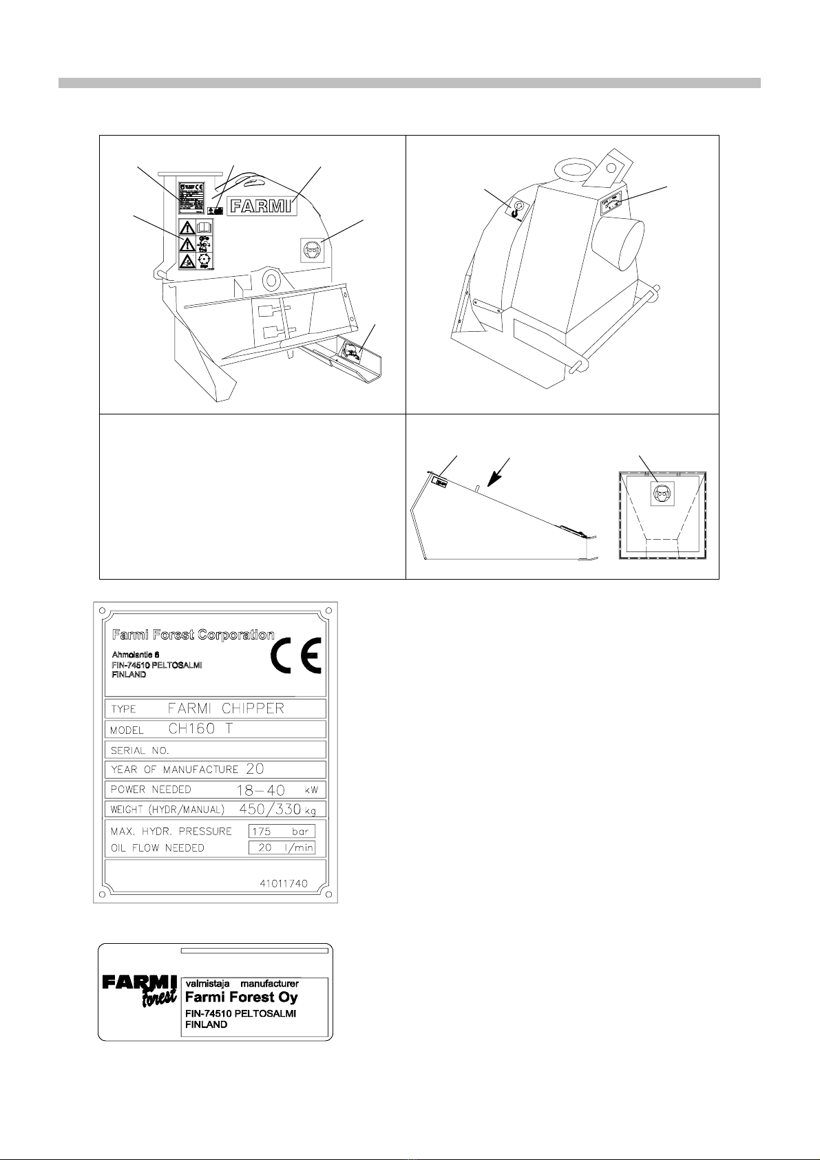
CH 160
7
1.4.OILS AND GREASES
DAlways use the oil grades recommended by the manufacturer.
DUse the recommended oils in cold conditions.
DNever mix different fluids or oils with each other.
DFollow the manufacturer’s lubrication instructions.
1.5.MAINTENANCE
DModifications without the manufacturer’s permission are prohibited.
DRemember that the manufacturer of the machine is not responsible for damage that is caused by:
Dmodifications made without the manufacturer’s permission
Duse of non---original spare parts
Dnormal wear
DSafety devices must be re---fitted immediately after maintenance.
DNever try to take hold of moving parts when the engine is running.
DEnsure that the machine cannot be started during maintenance.
DElectrical and hydraulic failures are to be repaired by authorized personnel only. The same applies to the welding of
load---bearing structures.
DFollow the maintenance intervals listed, and perform the indicated annual safety inspections.
1.6.LIFTING
DLift only with the proper type of lifting device, and ensure that it has an appropriate lifting capacity.
DEnsure that the lifting equipment is in good working condition. The lifting equipment must be inspected regularly.
DEnsure that you know the weight of the load to be lifted and never exceed the lifting capacity stated by the manufacturer
of the lifting device.
DSelect routes for lifting that pose no danger.
DLiftingpointsaremarkedonthemachineswithstickersasshown in the figure. Use only the marked points for lifting the
machine.
1.7.STORAGE
DIf the chipper is to be stored for a long period, lubricate the knives with, for example, petroleum jelly.
DEnsure that the water drainage holes in the lower chamber are unobstructed.
2.SAFETY INSTRUCTIONS FOR HYDRAULIC SYSTEMS
1. Hydraulic systems must be serviced by qualified, experienced hydraulics mechanics only.
2. Check the machine for any leaks and repair them before using the machine.
3. Clean the area to be repaired. Do not use solvents to clean components.
4. Never repair the hydraulic system when it is pressurized.
5. Support the machine before servicing or making repairs. Do not detach the cylinders or their valves before supporting
the machine.
6. When replacing hydraulic components and hoses, use original spare parts or parts recommended by the
manufacturer. In particular, ensure that the pressure classes correspond to the operating pressure.
7. If oil gets in the eyes, rinse them thoroughly with water and consult a doctor.
8. Oil can be removed from skin by wiping and washing. Use safety equipment when handling oils and greases.
9. Prevent hydraulic oil from escaping into the environment. Waste oil must always be collected in a container to keep the
environment clean!
10.When working in ecologically sensitive areas, use bio---oils.
11.Keep oil indoors in closed, original containers. Pour the oil into the tank directly from the container.
12.All caps, funnels, screens, and filling holes must be clean.

CH 160
8
3.STICKERS AND PLATES
These plates and stickers must be found on the chipper. Replace missing plates or stickers immediately.
1
3
4
5
5
6
6
7
2
8
9
T1
T2
Number 1.Machine plate (41011740).
Number 2.Manufacturer sticker (40605214).

CH 160
9
FARMI
20140489
41015750 T3
Number 3.Note! (41015500)
Note!
See operation and maintenance manual..
Note!
Stop the engine and remove the PTO shaft for
maintenance.
Risk of cutting injury!
Stop the engine and wait until the disk has
stopped.
Number 4.GS sticker (51971919).
Number 5.Hearing protection symbol.
Wear hearing protection. (40142080). 2pcs.
Number 6.Lifting point sticker (41014270). 2 pcs.
Number 7.Rotation speed sticker (40141160).
Number 8.“FARMI” --sticker (20140489).
Number 9.Foot mounting instructions ---sticker
(41015750).

CH 160
10
3.PRESENTATION
The Farmi CH160 is a double---knife disk cutter for chipping
wood up to ∅160 mm, for processing wood waste from,
e.g., the side of jogging tracks or roads, and for other
environmental chipping duties. The chipper can be driven
by a tractor with a rating of 10–40 kW. The chipper can also
be driven by a separate hydraulic motor.
CH160 accessories:
DSingle---motor hydraulic feeder, mechanical or gravity
hopper;
DIndependent hydraulic unit HD11;
DSeparate hydraulic motor drive;
D“Wille” adapter;
D“Bobcat“ adapter;
DBelt transmission 160 T
4.MAIN COMPONENTS
1. UPPER CHAMBER
2. LOWER CHAMBER
3. DISK
4. KNIFE
5. VERTICAL ANVIL
6. HORIZONTAL ANVIL
7. TWIG BLADE
8. DISCHARGE PIPE
9. LID
10.HYDRAULIC MOTOR (OPTIONAL)
11.BELT TRANSMISSION 160 T (OPTIONAL)
13
2
5
7
8
6
4
9
10
11
Fig. 1.Main components.

CH 160
11
5.DIMENSIONS
1,200 short discharge pipe
1,910 long discharge pipe
Fig. 2.CH160 dimensional drawing
6.TECHNICAL DATA
CH 160
Type disc chipper
Output 5--20 m3/h
Chip length 13 mm
Max. wood diameter 160 mm
Power demand 10 --40 kW
PTO RPM 540 or 1000 rpm
Number of knives 2
Power source tractor or a separate hydraulic motori
Mounting 3--point
Chipper weight CH 160 240 kg
CH 160T 284 kg
Disc diameter 670 mm
Disk weight 100 kg
Discharge pipe360oturning
Opening of upper chamber to one side
Feeder manual chute or hydraulic feeder
Sound pressure level
Sound power level
CEN/TC144 WG8N16
102 dB (A)
120 dB (A)
Table 1.Technical data.

CH 160
12
5.LIFTING
Lifting points for each machine are mar-
ked with hook symbols.
CAUTION!
CH 160 240 kg
CH 160 T 284 kg
Without feeder
Fig. 3.CH160 Lifting point.
6.ASSEMBLY INSTRUCTIONS
1. Attach the feeder to the chipper from the left side
with the hinge pin (1) and from the right side with
two bolts (M12) (2). Remember to install the
securing bolts (M6) (3). See Fig. 4.
1
33
3
2
2
Fig. 4.Mounting the feeder.
2. Attach the discharge pipe to the chipper with two
M10 bolts and one M16 bolt.
3. Mount the chipper on the tractor’s 3---point hitch.
4. Install the PTO shaft.
5. Check that the length of the PTO shaft is correct for
different hitch positions. For instructions on cutting
the shaft, see Section 6.1.
6.1.CUTTING THE PTO SHAFT
The use of too long a PTO shaft with a
3-point hitch could damage the chipper’s
bearings or the tractor’s PTO shaft. Both
halves of the PTO shaft must be shortened
equally.
C
AUTION!
Recommended PTO shafts:
Bondioli & Pavesi A6 + (RA1 with overrunning clutch.)
Walterscheid W2400 + (F3 with overrunning clutch.) If the
tractor features a PTO brake, an overrunning clutch must
be used (e.g., Ford).
1. Mount the machine on the tractor’s 3---point hitch.
2. Lift the machine with the hitch so that the distance
between the splined shafts is at its shortest.
A
Fig. 5.Measure distance A when the distance between
the splined shafts is at its shortest.
3. First, cut the thicker shield to the correct length (1).
Remember the 20 mm clearance. Then, cut a similar
length from the profile tube (2). Shorten the other
PTO shaft half similarly. Remove burrs using a file.
A
1 2
20
Fig. 6.Shortening the PTO shaft.
4. Insert the inner tube in the outer tube and carefully
move the machine up and down. Ensure that the
shaft was shortened sufficiently. Check that the shaft
has a 20 mm clearance.
In addition, move the machine sideways and ensure
that the PTO shaft does not bottom.

CH 160
13
6.2.MOUNTING ON THE WILLE 445 ADAPTER (Mounting kit 43510500)
DAttach the top link brackets of the adapter and chipper together with M20 pin and nut. (1)
DAttach the grabbers to the chipper’s drawbar assy with four bolts (M16) (2).
DThe grabbers have three grooves for the drawbar of the drawbar assy. Attach the grooves of the grabbers (3) so that the
chipper is as vertical as possible at the operating position.
1
2
3
1
2
Fig. 7.Mounting on the Wille 445 adapter.

CH 160
14
6.3.MOUNTING ON THE BOBCAT ADAPTER (Mounting kit 03510800)
DThe mounting assembly replaces the drawbar assy on the chipper frame.
DAttach the mounting plate to the top link brackets of the chipper with M20 pin and nut (1).
DAttach the left and right bracket to the chipper with four bolts (M20) (2).
DAttach the upper beam with four bolts (M12) (3).
DAttach the upper beam to the mounting plate with four bolts (M12) (4).
DConnect the hoses with quick---couplers to the Bobcat. Note the flow directions (see next page).
2
1
3
4
Fig. 8.Mounting on the Bobcat adapter.

CH 160
15
6.4.INSTALLING THE HD 100
DThe chipper can be driven with a separate hydraulic motor coupled to the chipper shaft.
1. Install the motor bracket on the chipper frame as shown in the figure.
2. Attach the coupling sleeve with the keyway facing the hydraulic motor.
3. Attach the hydraulic motor to the motor bracket. Check that the coupling sleeve is on the chipper’s splined shaft.
4. Connect the hydraulic hoses to the hydraulics of the drive machine.
Pressure P
Tank T
Fig. 9.Installing a separate hydraulic motor.

CH 160
16
6.5.INSTALLING THE 160T i=2.1 BELT
TRANSMISSION
1. Remove the PTO guard and install to the cover plate
(1). Remove the mounting bolts of the small cover
plate and remove the cover plate (2) from the
mounting frame. These components will not be
needed later. See Figure 10.
2. Attach the upper belt pulley assembly (3) and the
regulator plate (4)to the chipper with the M12 bolts (5).
Tighten the bolts lightly so that the bearing housing
can be moved. See Figure 11.
3. Install the belt tightener (6) with the pin (7) and the
adjusting assembly with the pin with hole (8). Secure
the pins with cotter pins.
4. Install the belts on the upper belt pulley.
5. Push the lower belt pulley (9) onto the splined shaft
without thetighteningcone(10)whileplacingthebelts
into the grooves of the lower belt pulley.
6. Install the lower belt pulley tightening cone, NordLock
lock washer pairs, and tightening cone bolts (M12)
(11). Tighten lightly so that the lower belt pulley can be
moved on the splined shaft.
7. Check the alignment of the belts --- see Figure 12.
Adjust the alignment of the belt pulleys by moving the
upper belt pulley bearing housing and the lower belt
pulley.
8. Tighten the bolts of the upper belt pulley bearing
housing and the bolts of the lower belt pulley
tightening cone (5 and 11) M12 to 80 Nm.
9. Re---check the alignment of the belts and adjust if
necessary.
10.Adjust the belt tightener so that the roller touches the
belts lightly, then tighten the adjusting bolt (12) by two
to three turns. See Figure 13.
Be careful not to over--tighten, as this could
damage the belts!
11.Attach the plate (1) to the mounting frame with bolts
M8 (13).
12.Mount the chipper on the tractor. To check that
everything is in order, run the chipper for a while at
slow speed.
13.The belts must be run in, first without load for about ½
hour and then with the chipper loaded lightly for the
first 8 hours of actual use.
14.Observe the tightness of the belts and, if necessary,
adjust with the adjusting bolt (12).
1
2
Fig 10.Removing the covers.
3
4
5
6
7
8910
11
Fig 11.Installing the 160T belt transmission.
0,5 mm
+
--
Fig 12.Belt alignment.
12 13
1
Fig 13.Installing the 160T belt transmission cover plate.

CH 160
17
7.OPERATING THE CHIPPER
7.1.INSPECTIONS PRIOR TO OPERATION
DPark the chipper on level, hard ground.
DStop the tractor’s engine and ensure that the chipper
is fully stopped before carrying out the inspections.
DCheck that the disk rotates freely by turning the shaft,
and ensure that there are no foreign objects inside the
chipper.
DEnsure that all protective devices are intact and in
place. Removal of the covers is prohibited.
DDirect the discharge pipe so that flying chips do not
pose a risk to the operator or anyone else.
7.2.STARTING THE CHIPPER
DStartthechipperatlowtractorenginespeedand
increase the speed slowly to the required chipping
speed (540/1,000 rpm).
DThe chipper is now ready for chipping.
7.3.STOPPING A TRACTOR---DRIVEN
CHIPPER
DSlow the tractor engine speed to idle before
disengaging the PTO. This is especially important with
tractors featuring a PTO brake (e.g., Ford). Turn the
PTO control lever slowly to the OFF position.
7.4.STOPPING A HYDRAULIC MOTOR
DRIVEN CHIPPER
DIMPORTANT! When the chipper is driven by the
HD100, it is extremely important to slow the driving
engine speed to idle before disconnecting the
hydraulics, to prevent cavitation.
Never disconnect the hydraulics from high
rpm. This will cause a risk of cavitation and
may damage the hydraulic motor.
Check that no sounds indicating cavitation
canbeheardfromthehydraulicmotor.
CAUTION!
After stopping the chipper, wait for all
movement to stop. The disk continues ro-
tating like a flywheel after the PTO is disen-
gaged.
DANGER!
7.5.CHIPPING
DBefore feeding in the material to be chipped, ensure
that the wood is free from nails, stones, etc.
DFeed the wood from a standing position on the left side
of the feeder.
DPush the wood inside the feed chute until chipping
starts. Let go of the wood as soon as the self---feeding
starts.
DIf you are using a hydraulic feeder, refer to the separate
chipping instructions in the feeder manual.
Do not use the chipper in temperatures
below --20_C. This is to avoid damage
due to brittleness – especially in the
knives – caused by the cold. Avoid chip-
ping wood that is frozen solid, as self--
feeding is reduced in this case.
CAUTION!
ROTATING KNIVES!
Knives can cause cutting injury. Do reach
inside the feed chute with hands or feet.
DANGER!
FIRE HAZARD!
Always keep adequate fire--fighting
equipment on hand when using the chip-
per. Check the outside temperature of the
chipper regularly. If the chipper heats up
abnormally, stop the chipper and deter-
minethecauseoftheoverheating.
Check the temperature of bearings regu-
larly.
Pay special attention to careful mainte-
nance, and keep the chipper free from
dust.
Ifthechipperstartssmoking,pourwater
down the feed chute.
WARNING!
7.6.REDUCING THE POWER DEMAND
When using a small tractor to power the CH160 chipper,
select a PTO speed of 540 rpm. Run the tractor at full
engine speed.
If the tractor’s engine speed still decreases during
chipping, reduce power demand by altering the chipper to
cut with one knife.
The chipper is altered for single---knife operation simply by
removing one knife and attaching it to the other side of the
disk as a counterbalance, to retain the balance of the disk.
Since the chipper is self---feeding, the feed speed of wood
is also halved.
1. See Sections 9.1., “Removing the upper chamber”
and 9.2., “Sharpening the knives”.
2. Place a spring washer on the bolt. Turn the lock nut on
the bolt and tighten to 45 Nm.
3. Place another spring washer on the bolt and turn the
bolt through the knife into the disk. See Fig. 14.
Tighten the bolts to 45 Nm. Attach the knife using all
four bolts.
4. Interchange the cutting and counterbalance knives
regularly to ensure the balance of the disk.
SPRING WASHERS
M10 X 40
NUT M10
Fig. 14. Remove one knife and attach it to the other side
of the disk. The dotted line shows the knife in its
normal cutting position.

CH 160
18
8.PERIODIC MAINTENANCE
Always disengage the PTO and stop the
tractor and chipper fully before mainte-
nance or repair work.
Ensure that the disk is fully stopped be-
fore inserting anything inside the feed
chute.
Lock the disk before maintenance or re-
pairs.
Park the chipper on hard, level ground to
avoid it falling over.
Wear protective gloves when handling
knives or anvils.
WARNING!
8.1.LUBRICATING THE BEARINGS
DThe bearings are lubricated at the factory, and a similar
lubricant should be used for subsequent lubrication
(Shell Alvania Grease R 3. or Kendall L427). An
excessive amount of grease causes overheating and
impairs lubrication.
DLubricate the bearings every 200 working hours or at
least once a year.
1. Open the upper bearing housing --- see bearing
housing assembly drawing, Fig. 28.. Remove old
grease as carefully as possible and replace it with new
grease. Do not fill the bearing housing with grease.
2. Install the upper bearing housing and tighten to 50
Nm.
8.2.LUBRICATING THE PTO SHAFT
DLubricate the PTO shaft prior to operation and
regularly, as shown in Fig. 15..
DLubricate the inner surface of the PTO shaft, accessed
via the outer profile tube.
DLubricate the shield tubes in wintertime to prevent
them from freezing and sticking.
Lubricate the shield
tubes in wintertime to
prevent them from
freezing and sticking
Swing the joints sideways for lubrication
8h 8h
20 h
Lubricate the outer profi-
le tube’s inner surface
h = working hours
Fig. 15.Lubrication points and intervals for the PTO shaft.
8.3.PERIODIC INSPECTIONS
DWith new machines, check the mounting bolts for
tightness after the first operating hour, tightening them
if necessary. Tightening torques are shown in table 2.
DCheck the mounting bolts for tightness once a week.
DThe knife---to---anvil clearance is adjusted to the
specified values. For instructions on adjusting the
clearance, see Section 9.7.
3
2
1
4
5
Fig. 16.Checklist for tightening and checking clearances.
Item Width across flats,
mm (inches) Tightening torque, Nm
(lbf)
1. Check the knife bolts for tightness. 17 mm (11/16”) 60 (44 3/16)
2. Check the bearing housing bolts for tight-
ness
on both sides.
19 mm (3/4”) 80 (55 15/16)
3. Check the anvil bolts for tightness. 24 mm (15/16”) 200 (147 15/16)
4. Check the clearance between knives and
vertical anvils. 19 mm (3/4”) 1.2–1.5 mm (0.05–0.06”)
5. Check the bearings for radial clearance. 0.02–0.03 mm (0.0008–0.0012”)
Table 2.Tightening torques and clearences.

CH 160
19
9.KNIFE AND ANVIL MAINTENANCE
Read the safety instructions. The disk
continues rotating like a flywheel after
the PTO is disengaged.
DANGER!
CAUTION!
Wear protective gloves
when handling knives or anvils.
9.1.OPENING AND REMOVING THE UPPER
CHAMBER
DRemove the upper chamber (A) securing bolts (M6)
(B) and fastening bolts (M12) (C). Turn the upper
chamber to the side.
DTo remove the upper chamber, remove the securing
bolt (M6) (D) and hinge bolt (M12) (E).
DLock the disk with the lock bolt Fig. 18.
DRemove the feeder or turn it to the side.
C
D
E
A
B
Fig. 17.Removing the upper chamber.
9.2.REMOVING THE KNIVES
Lock bolt
Fig. 18.Locking the disk and removing the lock nuts.
1. Remove the knife lock nuts (M10). Fig. 18.
2. Remove the knife fastening bolts (M10). Turn the
wrench in such a way that your hands would not hit
the knife if the wrench should slip. Fig. 19.
Fig. 19.Removing the knife fastening bolts.
9.3.SHARPENING THE KNIVES
CAUTION!
Sharpen all
k
nives equally.
This ensures disk balance.
Avoid heating the knife during sharpening.
Wear protective gloves when handling
or anvils.
The knives need sharpening when:
DThe self---feeding of wood has decreased;
DThe power demand has increased;
DThe chip surface is rough.
Normally, the knives can be sharpened several times
without actually being removed (with, e.g., a sharpening
stone or belt grinder).
More thorough conditioning is carried out with a surface
grinder, with the knives removed.
The new knives are sharpened to a concave shape,
R=200. The sharpening angle is 30°and hone angle is
45°. The hone angle prevents the edge from breaking.
Fig. 20.
About 0.3 mm (0.01”)
Fig. 20.The profile of a concave knife

CH 160
20
It is recommended that the knives be sharpened to a
concave shape. If this is not possible, the knife is
sharpened to a flat profile. Fig. 21.
About 0.3 mm (0.01”)
Fig. 21.A knife with a flat profile
The hone angle is ground to a 45°angle with two to three
longitudinal strokes, using a level sharpening stone.
Burrs are removed from the knife fastening bolt side,
grinding with the surface.
Fig. 22.
Fastening bolt side
Fig. 22.Final grinding of the knife.
9.4.REMOVING THE ANVILS
The chipper features both a vertical and horizontal anvil.
To remove the anvils, open the fastening bolts (A) and
(B) (M16). The horizontal anvil fastening bolt (B) is
located below the feed opening. Fig. 23.
Vertical anvil
Horizontal anvil
A B
Fig. 23.Anvil fastening bolts
9.5.SHARPENING THE ANVILS
If you notice wear or rounding of the inner edge of the
anvil, sharpen the anvils so that the original angles are
retained. Fig. 24.
57 °
Vertical anvil profile
72 °
Horizontal anvil profile
Fig. 24.Anvil profiles.
9.6.INSTALLING THE KNIVES AND ANVILS
DCheck the condition of the fastening bolts and nuts.
DInstall the knives and anvils and tighten the fastening
bolts to the torques specified in Table 2..
DA d j u s t t h e k n i f e --- t o --- a n v il cl e a r a n c e . Fo r m or e
information on adjusting the knife---to---anvil
clearance, see Section 9.7.
9 . 7 . A D J U S T I N G T H E K N I F E --- T O --- A N V I L
CLEARANCE
The need for adjusting the anvils is determined by the
amount the knives are sharpened. Always check and, if
necessary, adjust the clearance between knives and
anvils:
DAfter a heavy sharpening;
DIf the knives were removed --- for example, due to
sharpening;
DIf new knives are replaced.
Check the clearance with a feeler gauge.
1. Loosen the anvil fastening bolts (A) and (B) (M16). Fig.
23.
2. Turn the disk so that a knife and the anvil are aligned.
Place a feeler gauge between the knife and anvil.
Adjust the vertical anvil clearance with the adjusting
nuts (M12) (C, Fig. 25.) to 1.2–1.5 mm (0.05–0.06”).
3. Tighten the adjusting nuts (C) and anvil fastening bolts
(A).
4. Adjust the horizontal anvil clearance at the front edge
to 4–5 mm (0.16 – 0.20”).
5. Tighten the fastening bolt (B).
6. R e --- c hec k t h e k n i f e --- t o --- anvil c lea r a n c es .
AC
Fig. 25.Vertical anvil fastening and adjustment.
Other manuals for CH 160
1
Table of contents
Other Farmi Forest Chipper manuals
Popular Chipper manuals by other brands

Nortrac
Nortrac 296025 Instructions for Installation/Set-up, Operation, Servicing, & Storage

Snapper
Snapper LS5000 parts manual

Timberwolf
Timberwolf TW 280TDHB instruction manual

Billy Goat
Billy Goat TERMITE TKD502H Operator owner's manual

Skibo
Skibo PEQUEA CX550 Operator's manual

Echo
Echo Bear Cat CH500H(74500) specification