FarmTek MWH-180 User manual

INSTALLATION AND OPERATING
INSTRUCTION
WARNING : If the information in this instruction is not followed exactly, a fire or
explosion may result causing property damage, personal injury or death.
- Do not store or use gasoline or other flammable vapors and liquids in the vicinity of this or
any other appliance.
- HAT TO DO IF YOU SMELL GAS
• Do not try to light any appliance.
• Do not touch any electrical switch; do not use any phone in your building.
• Immediately call your gas supplier from a neighbor's phone.
Follow the gas supplier's instructions.
• If you cannot reach your gas supplier, call the fire department.
- Installation and service must be performed by a qualified installer, service agency or the
gas supplier.
INSTALLER : Leave this manual with the appliance.
CONSUMER : Retain this manual for future reference.
Model MWH-180
Residential indoo unit,
Manufactu ed home (mobile home)

INDEX
SPECIFICATIONS ---------------------------------------------------------------------------- 1,2
PERFORMANCE ------------------------------------------------------------------------------ 2
FEATURES ------------------------------------------------------------------------------------- 3
FOR YOUR SAFETY READ BEFORE OPERATING -------------------------------- 4-10
ABOUT HOT WATER ------------------------------------------------------------------------ 11
SCALDS - FIRST AID------------------------------------------------------------------------ 11
REMOTE CONTROLLER OPERATION ------------------------------------------------ 12,13
USE IN THE LIME-RICH WATER (HARD WATER) AREA ------------------------ 14
CAUTION---------------------------------------------------------------------------------------- 15
PREVENTION OF FREEZING DAMAGE DURING WINTER SEASON -------- 16,17
FOR YOUR SAFETY READ BEFORE OPERATING -------------------------------- 18
OPERATING INSTRUCTIONS ------------------------------------------------------------ 19
DAILY INSPECTION AND MAINTENANCE ------------------------------------------- 20,21
IN CASE THE UNIT REMAINS UNUSED FOR A LONG TIME ------------------- 21
FAULT MONITOR ----------------------------------------------------------------------------- 22,23
TROUBLE SHOOTING AND SOLUTION ---------------------------------------------- 24
EXPLODED VIEW ---------------------------------------------------------------------------- 25,26
PARTS LIST ------------------------------------------------------------------------------------ 27
INSTALLATION INSTRUCTIONS -------------------------------------------------------- 28-31
DIMENSIONS ---------------------------------------------------------------------------------- 32
TEMPLATE OF L TERMINATION INSTALLATION ---------------------------------- 33
SUGGESTED PIPING-BASIC INSTALLATION --------------------------------------- 34
SUGGESTED PIPING-CIRCULATION SYSTEMS ----------------------------------- 35
VENT PIPE INSTALLATION --------------------------------------------------------------- 36-39
HIGH ALTITUDE ------------------------------------------------------------------------------ 40
VENT PIPE INSTALLATION --------------------------------------------------------------- 41-53
GAS LINE SIZING CHARTS --------------------------------------------------------------- 54
GAS PIPING ------------------------------------------------------------------------------------ 55
WATER PIPING-------------------------------------------------------------------------------- 55
PRESSURE RELIEF VALVE --------------------------------------------------------------- 56
ELECTRICAL CONNECTION ------------------------------------------------------------- 56,57
WIRING DIAGRAM --------------------------------------------------------------------------- 58,59
DIAGNOSTIC POINTS----------------------------------------------------------------------- 60
SCHEMATIC DIAGRAM--------------------------------------------------------------------- 61
WIRING REMOTE CONTROLLER ------------------------------------------------------- 62
MAIN REMOTE CONTROLLER CMR-2250 (P/N 3748)---------------------------- 63
BATH REMOTE CONTROLLER YST-2250 (P/N 3749) ----------------------------- 64
TESTING OPERATION ---------------------------------------------------------------------- 65
INSTRUCTIONS FOR CONVERSION--------------------------------------------------- 66
WARRANTY ------------------------------------------------------------------------------------ 70

- 1 -
rebmunledoM081-HWM
ecnailppafoepyTretaehretawwolfsuounitnocsaG
epytsagdevorpp enaporProlarutaN
noitallatsnIgnignahllaW/ylnoroodnI
erutarepmettniopteS
)etomertuohtiw( Fº021-gnittesyrotcaF
etomerhtiwegnarerutarepmeTFº041-69:rellortnocetomeR
metsystsuahxEnoitsubmocdecrof-tnevtceriD
snoisnemiD
)mm016("23/142thgieH
)mm053("23/5231htdiW
)mm012("8/38htpeD
thgieW.sbl34
snoitcennoC
TPNM"4/3saG
TPNM"4/3telniretaW
TPNM"4/3teltuoretawtoH
metsysnoitingInoitingicinortceletceriD
noitpmusnoclacirtcelE
sttaw16lamroN
sttaw7.3norellortnocetomerhtaB/niaMybdnatS
sttaw48noitarepotsorf-itn
retawmuminimdednemmoceR
erusserpylppus
ISP51
)ecnamrofrepmumixamrofisp57-52dednemmocer(
erusserpylppusretawmumixaMISP051
ylppusrewoP zH06-V021Cecnailpp
)latigid(V21CDrellortnocetomeR
SPECIFICATIONS

- 2 -
Safety devices
Flame failure - Flame rod
Over heat switch 212º F
Over heat limit 203º F
Thermal fuse 363º F
utomatic frost protection
Fan motor rpm check - PCB
Over current - Fuse (5 amp)
Remote controller (option) CMR-2250(P/N 3748) Main control kitchen / laundry
YST-2250(P/N 3749) Bathroom control
Remote controller cable (option) Nonpolarized two core cable
Clearance from combustibles
Top of heater 12" (30.5cm)
Front of heater 6" (15.2cm)
Sides of heater 2" (5.1cm) [6"(15.2cm) for reading of labels]
Back of heater 0" (0cm)
Floor 12" (30.5cm)
Vent pipe 0" (0cm)
SPECIFICATIONS
MUMIXMMUMINIM
noitpmusnocsaG saGlarutaNh/utB000,081h/utB000,02
saGenaporPh/utB000,081h/utB000,02
erusserpylppussaG saGlarutaN.C.W"5.01.C.W"4
saGenaporP.C.W"41.C.W"8
erusserpsagdlofniaM saGlarutaN.C.W"5.2.C.W"4.0
saGenaporP.C.W"5.2.C.W"4.0
yticapacretawtoH MPG8.5-85.0
)esirFº45(yticapacretawtohmumixaMMPG8.5
PERFORMANCE

- 3 -
FEATURES
The MWH-180 is a new advanced technology water heater. It produces hot water, continuously,
at the preset temperature of 120ºF. For optimal performance, we recommend the use of the
optional remote controllers.
The MWH-180 will never run out of hot water. Hot water is available as long as a hot water faucet
is open.
s soon as a hot water faucet is opened, a signal goes to the microprocessor to start the burner
operation. Closing the faucet sends the shut down signal to stop the burner.
The MWH-180 is furnished with an electronic ignition system.
This feature eliminates gas usage when no hot water is being used, leading to significant savings
in energy and money.
The advanced control system uses a sensor to continuously maintain the outgoing water
temperature.
The safety protections of the microprocessor include limiting the maximum temperature of the hot
water. The maximum temperature of water, without using the remote controllers, is preset at 120ºF.
fault monitor will display malfunction codes on the remote controllers. This simplifies trouble
shooting during service calls.
The MWH-180 is designed to prevent varying temperature of hot water when the faucet is cycled
on and off. There is also a quick response mode for rapid heating.
The dimensions of the MWH-180 use less wall space and no floor space.
The remote controllers are a crisp, modern design to blend in any decor.
Endless loop in input and output control ensures a stable flow of hot water.
Low NOx. The Rich - Lean design of the burner produces minimum nitrous oxides.
Greater reliability of electric components due to the potted control circuit board.

- 4 -
FOR YOUR SAFETY READ BEFORE OPERATING
For your safety and proper use of the un t.
Read and understand the following important symbols before use.
The cases shown below are classified by the degree of risk and damage.
Be sure to follow the instruction symbols for your safety.
"Danger" indicates that serious injuries or even death to the user may result
if the instruction is neglected and the unit is mishandled.
"Warning" indicates the possibility that serious injuries or even death to the
user may result if the instruction is neglected and the unit is mishandled.
"Caution" indicates the possibility that some injuries to the user, and/or
material damage may result if the instruction is neglected and the unit is
mishandled.
Each mark indicates:
General instruction
Danger
Warn ng
Caut on
Electric shock
Fire
High temperature
General prohibited
No flammables
Do not touch
Do not disassemble.
Never fail to do.
Ground

- 5 -
FOR YOUR SAFETY READ BEFORE OPERATING
Danger
Unfastening of the vent pipes can cause a shortage of oxygen, fire, or overheating.
Check to make sure the flue pipe or vent pipe is properly connected.
Leaking exhaust gas indoors poses a danger if the pipes are unfastened during operation.
Blockage in the vent pipes.
Make sure the flue pipe and vent pipe are
clear of any blockage such as bird's nest,
or debris such as leaves, twigs or weeds.
The blockage may cause the leakage of the
exhaust gas indoors during operation,
which is dangerous.
Check for gas leak. (May cause fire.)
If a gas leak is noticed, stop using the unit immediately and close the gas valve, then contact
your service person, or the gas supply company.
Do not light any appliance, disconnect/connect the power plug or touch any electric switch.
Close the main gas valve in case the unit is not used for a long time.
In winter make sure snow does not block
the vent pipe.
Take necessary measures to prevent snow
drifts from blocking the outlet/inlet of the flue
pipe.
Close
Check
Check
Close
No open flame Proh b ted

- 6 -
FOR YOUR SAFETY READ BEFORE OPERATING
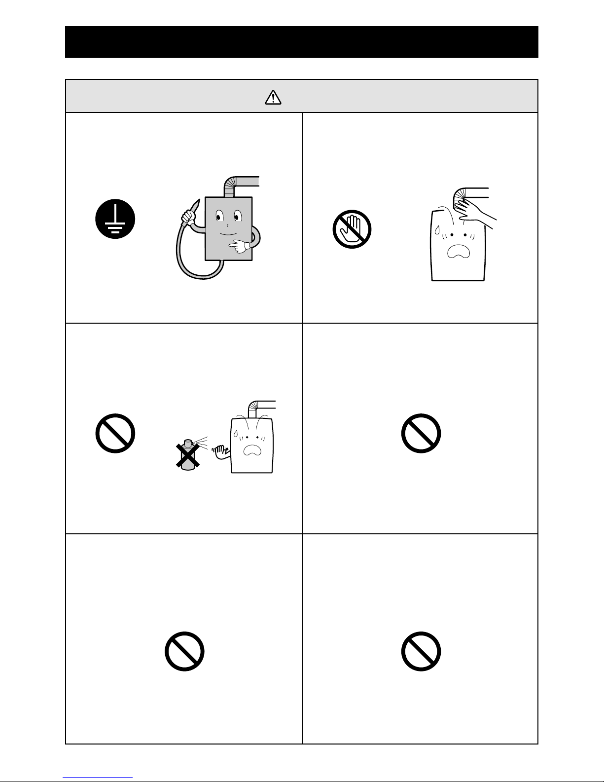
Caution to prevent scalding.
Check the water temperature by hand first before using shower or stepping into the bath tub.
Do not change the temperature setting while others are running hot water.
Gush of hot water may cause scalding or cold water may cause discomfort.
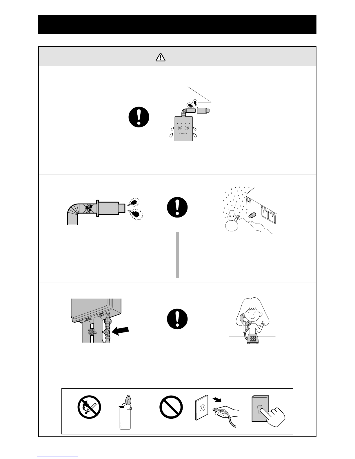
Measures to be taken in case of emergency.
When there is an emergency such as earthquakes, tornadoes, hurricanes or fire follow these
procedures.
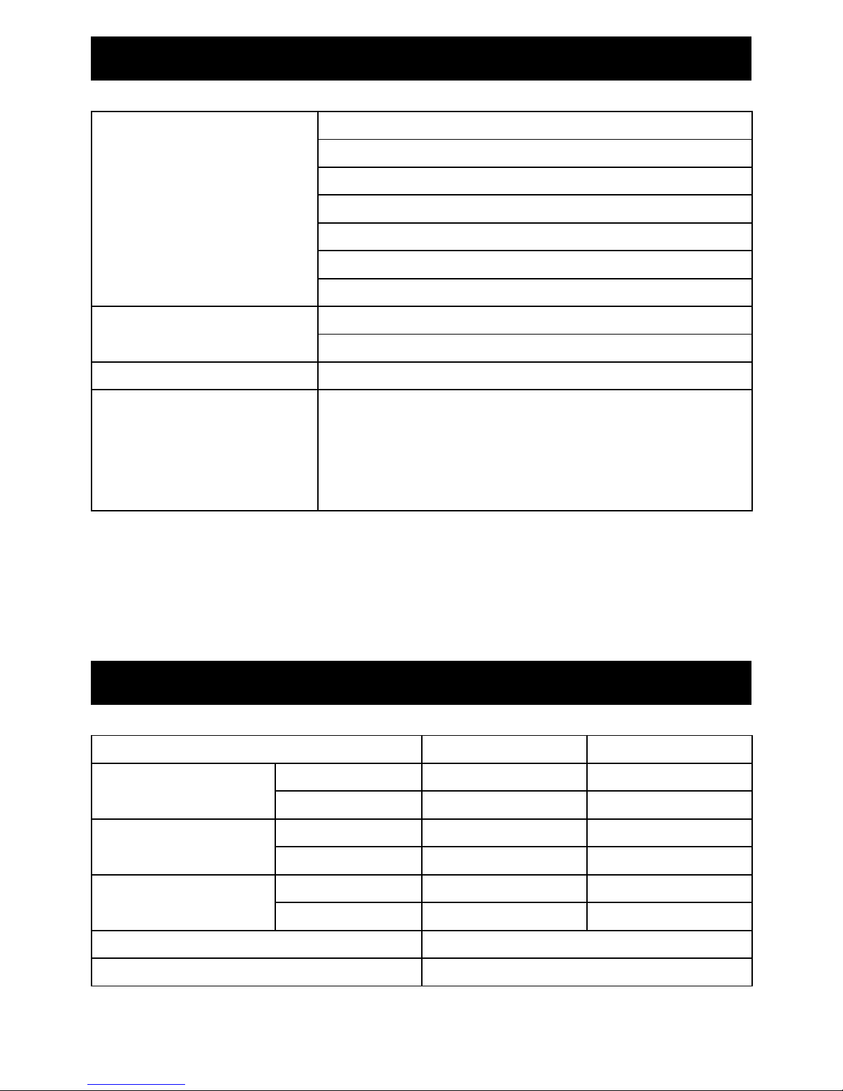
Confirm type of gas and power supply.
(Wrong gas type may cause incomplete combustion, explosive ignition or fire.)
Make sure to use the correct gas type as
well as power supply (voltage/frequency)
as indicated on the R TING L BEL
located on the side, of the cabinet.
Natural Gas or Propane Gas are stated
on the G S TYPE L BEL.
1. Turn off the hot water faucet.
2. Close the gas valve and the main water valve.
3. Turn off the main power.
Warning, in case of gas leakage, first close the gas
valve and wait for the leaked gas to disperse, then
turn off the main power supply.
4. Contact your service technician, or gas supplier.
Caut on
Check
ONLY FOR USE WITH
NATURAL GAS
REFER TO THE LOC L G S UTHORITY FOR CONFIRM TION ON THE G S TYPE, IF IN DOUBT.
DO NOT REMOVE THIS L BEL UNTIL THE PPLI NCE H S BEEN INST LLED ND TESTED.
Si vous ne savez pas le type de gaz, contactez le fournisseur de gaz ou les autorité locaux.
Enlevez pas cette etiquette jusqu´à l´appareil a été installer et verifie. 20457650
ONLY FOR USE WITH
PROPANE GAS
REFER TO THE LOC L G S UTHORITY FOR CONFIRM TION ON THE G S TYPE, IF IN DOUBT.
DO NOT REMOVE THIS L BEL UNTIL THE PPLI NCE H S BEEN INST LLED ND TESTED
Si vous ne savez pas le type de gaz, contactez le fournisseur de gaz ou les autorité locaux.
Enlevez pas cette etiquette jusqu´à l´appareil a été installer et verifie. 20457720
or
DIRECT VENT UTOM TIC INST NT NEOUS G S W TER HE TER
FOR INDOOR INST LL TION
N TUR L G S / PROP NE G S
CH UFFE-E U INST NT NÉ UTOM TIQUE À ÉVENT DIRECT POUR
INST LL TION INTÉRIEUR.
N T / GPL
NSI Z21.10.3-2004
CS 4.3-2004
Wiring Diagram inside Front Cover
Schéma du câblage derrière le couvercle avant.
Minimum clearances from combustible of non-combustible construction
Dégagements minimaux à assurer entre les parois de l´appareil et les constuctions combustibles ou
incombustibles
Back: 0 inch 0 po arrière
Front: 6 inches 6 po devant d´appareil
Top: 12 inches 12 po dessus
Side: 2 inches (6 inches for reading of labels) 2 po côtés (6 po pour lire l´étiquette)
FOR YOUR SAFETY
Do not store or use gasoline or other flammable vapors and liquids in the vicinity of this or any other
appliance.
This water heater is required to have with a pressure relief valve. For safe operation of the water heater
the relief valve must not be removed from its designated point of installation or plugged.
POUR VOTRE SÉCURITÉ
Ne pas entreposer ne utiliser d´essence ne d´autres vapeurs ou liquides inflammables à proximité de cet
appareil ou de tout autre appareil.
Ce chauffe-eau dôit être installer avec un soupape de décharge. Pour assurer le fonctionnement
sécuritaire du chauffe-eau, ne pas retirer ni obturer cette soupape de décharge.
PROP NE G S (GPL)N TUR L G S (Gaz Naturel)MODEL : MWH-180
180,000 Btu/h180,000 Btu/h
M X. INPUT
Debit calorifique max.
20,000 Btu/h20,000 Btu/h
MIN. INPUT
Debit calorifique min.
14.0 inches W.C.
14.0 pounces W.C.
10.5 inches W.C.
10.5 pounces W.C.
G S PRESSURE INLET M X.
Pression de gaz entrée max.
8.0 inches W.C.
8.0 pounces W.C.
4.0 inches W.C.
4.0 pounces W.C.
G S PRESSURE INLET MIN.
Pression de gaz entrée min.
2.5 inches W.C.
2.5 pounces W.C.
2.5 inches W.C.
2.5 pounces W.C.
G S PRESSURE M NIFOLD M X.
Pression d´admission max.
0.4 inches W.C.
0.4 pounces W.C.
0.4 inches W.C.
0.4 pounces W.C.
G S PRESSURE M NIFOLD MIN.
Pression d´admission min.
C 120V –
60Hz
ELECTRIC L R TING
Regime nominal électrique
150 PSI
M X. W TER PRESSURE
Pression d’eau max.
20457664
Warn ng
Tur n of f
Close
Close

- 7 -
FOR YOUR SAFETY READ BEFORE OPERATING
Warn ng
Pay attention to children. (cause of accident.)
Do not allow small children to play in the
bathroom or to play with the remote
controllers.
Disassembly, repair or modification of the
unit may cause fire, electric shock or other
accidents.
Do not disassemble or modify the units.
Never fail to ask for professional assistance
from your dealer for installation, removal,
auxiliary installation work, or connection to
solar units.
Caution for flammable items.
(May cause fire or explosion.)
Do not place any flammable items such as
gasoline, benzene, or spray cans near the
appliance.
Do not use them around the heater or the
exhaust vent terminal.
Take special care.
No rubber piping.
(May cause gas leakage or fire.)
Rubber pipe should never be used for gas
piping line.
Do not go out or sleep while leaving the hot
water running.
No installation outdoors or in the bathroom.
(May cause fire or electric shock or other
accidents.)
The unit is for indoor installation use.
Never install outdoors or in the bathroom.
Steam from the shower or bath can cause
corrosion or malfunction.
GASOLINE
Proh b ted
Warn ng
Tur n off
Tur n of f
Do Not D sassemble
Proh b ted
Proh b ted

- 8 -
FOR YOUR SAFETY READ BEFORE OPERATING
Caut on
Be sure to electrically ground the unit. Do not touch the exhaust vent pipe and
water heater during or immediately after
operation.
HOT!!
Ground Do not touch
Do not use hair spray or spray detergent in
the vicinity.
Do not install in locations where excessive
dust or debris will be in the air.
Do not turn off the water heater or change
the water temperature while someone is
bathing or washing. That may result in scalds
or burns.
Spray
Proh b ted Proh b ted
Proh b ted
Do not wipe remote controller with gasoline,
benzene, or detergents.
Proh b ted

- 9 -
FOR YOUR SAFETY READ BEFORE OPERATING
Confirm ignition, combustion and extinction.
lways check Flame logo indicator for
combustion and that the unit has shut down
by checking the operation lamp on the Main
or Bath remote controller.
Caut on
Do not allow the remote controller to get wet.
(May cause controller to fail.)
Do not install near electric appliances.
When installed near the TV or radio, it may
cause picture disturbance or sound
disturbance.
Flame logo nd cator
Check
Check
Check
Measures to be taken for lightning possibility.
(May cause failure.)
Temporary voltage surge caused by lightning
can damage the electronic parts.
Turn off the main power when you hear
thunder.
Provide adequate space around the unit for
service.
Make sure to have enough room around the
unit to ensure space necessary for
checking and maintenance.
Check
Pay attention to applications.
Do not use the unit for other applications than
domestic hot water supply and shower.
Commercial use, see warranty.
Check

- 10 -
FOR YOUR SAFETY READ BEFORE OPERATING
Use only genuine factory designated parts,
and accessories.
Instruction in case the unit is used in
lime-rich water (hard water) area.
Drain the residual hot water in the unit away.
Otherwise the lime may harden and deposit
in the pipe, causing lower efficiency and
damage to the unit. (refer to page 14)
The MWH-180 is designed primarily for
single family home use.
Not ce:
If used in a commercial application, a limited
warranty applies.
Water or hot water left in the unit for a long
time is not suitable for drinking or cooking.
Do not drink or use for cooking.
des gnated
part
Check
Check
Proh b ted
Caut on
Check

- 11 -
ABOUT HOT WATER
Hot water heater temperature over 125ºF can cause severe burns instantly or death from scalding.
Children, disabled and elderly are at the highest risk of scalding.
Feel water temperature before bathing or showering.
SCALDS - FIRST AID
1. Remove cloth ng; Remove all wet clothing quickly. Wet clothing retains the heat.
2. Apply cold water for 30 m nutes; Immediately submerge the burnt area in cold water for 30
minutes to reduce the heat in the skin, preventing deeper burning.
Never use butter, oils or ointment to cover the burn. They may retain the heat.
3. Keep the scalded person warm; Place a blanket around the person.
4. Seek med cal adv ce; Call your medical advice hotline and describe the scald, follow their
directions.
HOT!!
BURN
Warn ng

- 12 -
REMOTE CONTROLLER OPERATION
ON/OFF Button
Power switch to operate
this control.
D g tal Mon tor
Indicates the selected
water temperature.
Error messages flash in
the event of a failure.
Flame Logo Ind cator
Indicates that a hot water
faucet is open and that
control of the temperature
is taken at another
controller.
Flame Logo Ind cator
Indicates that a hot water
faucet is open and that
control of the temperature
is taken at another
controller.
UP/DOWN Button
Increase or decrease the
desired water temperature.
UP/DOWN Button
Increase or decrease the
desired water temperature.
PRIORITY Button
Priority button to set the
water temperature in
Bath remote controller.
PRIORITY Ind cator
Indicates this controller
has priority control over
the other controller.
Indicates this controller
has priority control over
the other controller.
PRIORITY Ind cator
ON Ind cator
Indicates power is on to
the system.
ON/OFF Button
Power switch to operate
this control.
D g tal Mon tor
Indicates the selected
water temperature.
Error messages flash in
the event of a failure.
ON Ind cator
Indicates power is on to
the system.
CMR-2250 (P/N 3748)
(Ma n remote controller)
YST-2250 (opt onal P/N 3749)
(Bath remote controller)
Th s remote controller s ntended to be used n the k tchen, laundry room or ut l ty area.
Th s remote controller s ntended for nstallat on n the bathroom.

- 13 -
REMOTE CONTROLLER OPERATION
Operat on of Ma n/Bath remote controller.
Please read these instructions carefully before using this appliance.
1. Turn on the ON/OFF button. (refer to page 12.)
2. The temperature display will illuminate at 108ºF.
3. The priority indicator will illuminate.
4. Select hot water temperature by pushing UP/DOWN button ( ) on the controller.
5. Turn on the hot water faucet. Flame logo indicator will illuminate after a short delay.
This indicator will remain illuminated until the hot water faucet is turned off.
6. The hot water temperature can be altered at any time during the operation by pushing
UP/DOWN button ( ) located on the controller.
PRIORITY control. (change.)
The temperature can only be controlled by the remote controller which has the priority indication.
Priority button is only located on the Bath remote controller.
When the priority switch is turned on, priority control over the water temperature is changed
voluntarily.
Do not turn off the water heater or change the water temperature while someone is bathing
or washing. That may result in scalds or burns.
or
• In case of installation of both a Main remote controller and a Bath remote controller with priority
button ON, when pushing priority button on Bath remote controller, the hot water temperature
will read 108ºF.
• In case of installation for Bath remote controller only, when pushing priority button on them,
hot water temperature will read 108ºF.
or
or
Warn ng

- 14 -
How to operate.
Perform the following steps after the hot water is used.
If control switch is not easily accessible :
Partially open the hot water faucet so that there is less than half gallon flow until the cold water
starts to run.
1. Turn the ON-O button off. 2. Turn on the hot water faucet.
Let the residual hot water completely run out.
Tur n of f
USE IN THE LIME-RICH WATER (HARD WATER) AREA
Caution
In case the unit is used in the lime-rich water (hard water) area, make sure to flush the
residual hot water away.
Otherwise lime may harden and deposit in the pipes causing low efficiency and damage to
the unit.
• Contact a qualified MPI service technician to remove lime once a year.
ailure to perform the annual maintenance will cause malfunction or damage to the heat
exchanger.
Damage caused by the lime build up is not covered by the unit's warranty.
If a “LC” code shows in the remote controller, call a technician to flush the system.
Tur n on
.
Turn off the hot water faucet when the cold
water starts to run.

- 15 -
The residual water in the unit.
Do not drink or cook with any of the water left in the unit or in the pipe for a long time because the
quality may have deteriorated.
Power failure in winter.
Prevent freezing by following steps “ (2) By running water from any faucet. ” or
“ ( ) By removing water in unit as freezing may cause damage to the unit. ” as freezing may
cause material damage to the unit. (refer to page 16,17)
Resetting after power failure.
Note :
When not using the remote controller : Ensure that the hot water faucets are turned off.
The unit will automatically reset after power is restored.
When using remote controller(s) : If the remote controller was turned ON, when power is restored,
the remote controller will be ON, and the unit will automatically reset and deliver hot water on
demand.
If the remote controller has been shut O , it will remain O . After power is restored, and the
remote controller is turned back ON, the unit will be ready to use at the next demand for hot water.
If an error code appears before the power outage, the unit will remain O unit the problem is
resolved.
In case damage is caused by natural disasters such as earthquakes,
tornadoes or hurricanes.
If gas or water leakage is suspected even though there is no apparent damage, shut off the Main
Gas valve, close the water valve, disconnect power supply, and check the extent of the damage.
Contact your local dealer for further assistance.
CAUTION

- 16 -
2. Turn on the hot water faucet.
Keep water running at about 1/10 gal/min
(400cc/min).
The unit or pipe is likely to be damaged by freezing, not only in the cold latitudes, but also in the
mild-temperature zones in winter season. Pay careful attention to prevent freezing pipes.
(1) Anti-frost heater. (automatic.)
(2) By running water from any faucet.
The power supply.
In extremely cold temperature (10º ) the anti-frost heater may not be sufficient.
The following step 2. or . should be tried to avoid freeze up.
1. Close the main gas valve.
This helps prevent freezing of the pipes and the valves as well.
Check the flow volume 30 minutes after this procedure as the flow may fluctuate.
Notice :
3. Turn off the main power.
Close
PREVENTION OF FREEZING DAMAGE DURING WINTER SEASON
Prevention of freezing.
Make sure electrical power is supplied to the heater.
The anti-frost heater keeps the water supply circuit warm inside the unit.
About 1/8" (4mm) thick
Tur n on
Caution

- 17 -
3. Turn on the hot water faucet.
Turn on a shower faucet if any.
( ) By removing water in unit as freezing may cause damage to the unit.
Close
1. Close the main gas valve.
Tur n on
4. Remove the drain plug and the water
filter. (drain stopper.)
5. Turn off the main power.
This is the best method for protecting the unit.
Although, freeze prevention is not possible for the pipe and the valve.
When operation is resumed, put the water filter (drain stopper) back on and check if water
runs from the hot water faucet by turning on the main water supply valve.
Notice :
Close
2. Close the main water supply valve.
PREVENTION OF FREEZING DAMAGE DURING WINTER SEASON

- 18 -
FOR YOUR SAFETY READ BEFORE OPERATING
A. This appliance does not have a pilot. It is equipped with an ignition device that automatically
lights the burner. Do not try to light the burner by hand.
B. BE ORE OPERATING : Smell all around the appliance area for gas. Be sure to smell next
to the floor because some gas is heavier than air and will settle on the floor.
WARNING : If you do not follow this instruction exactly, a fire or explosion may result
causing property damage, personal injury or loss of life.
C. Use only your hand to turn the gas control knob. Never use tools. If the knob will not turn by
hand, do not try to repair it, call a qualified service technician. orce or attempted repair may
result in a fire or an explosion.
D. Do not use this appliance if any part has been under water. Immediately call a qualified
service technician to inspect the appliance and to replace any parts of the control system and
any gas control that has been under water.
WHAT TO DO IF YOU SMELL GAS
• Do not try to light any appliance.
• Do not touch any electric switch, do not use any phone in your building.
• Immediately call your gas supplier from a neighbor's phone. ollow the gas supplier's
instructions.
• If you cannot reach your gas supplier, call the fire department.
Table of contents
Popular Water Heater manuals by other brands

BaltGaz
BaltGaz NEVALUX-5611 user manual

clage
clage German Pool DBN user manual

EDA
EDA Recup Eco 310L manual

CTC Union
CTC Union EcoZenith I 550 Installation and maintenance manual

State Water Heaters
State Water Heaters Sandblaster SBD30 150 NE Service handbook

Bradford White
Bradford White ElectriFLEX LD RE1 Series Service manual

Ariston Thermo
Ariston Thermo SGA X 120 EE Installation and maintenance instructions

TransTank
TransTank AquaModule Operator's handbook

Rointe
Rointe RD SERIES instruction manual

Girard Products
Girard Products GSWH-1 Service manual

A.O. Smith
A.O. Smith T-H3J-DV Service manual

STIEBEL ELTRON
STIEBEL ELTRON SHU 5 SL Operation and installation