FASTflo WH42 Guide
Working towards
a cleaner future
FASTflo
Installation Design Guide
This manual must be kept with the appliance October 2010
Part No E835
Continuous Flow Wall Hung Balance Flue
Water Heaters for Natural Gas an Propane
WH42, WH56, WHX56, LWH56, WHX56, LWHX56

Repro uction of any information in this publication by any metho is not permitte
unless prior written approval has been obtaine from An rews Water Heaters.
An rews Storage Water Heaters have been esigne an manufacture to comply
with current international stan ar s of safety. In the interests of the health an safety
of personnel an the continue safe, reliable operation of the equipment, safe working
practices must be employe at all times. The attention of UK users is rawn to their
responsibilities un er the Health an Safety Regulations 1993.
All installation an service on An rews Water Heaters must be carrie out by properly
qualifie personnel an , therefore, no liability can be accepte for any amage or
malfunction cause as a result of intervention by unauthorise personnel.
An rews Water Heaters’ policy is one of continuous pro uct improvement an ,
therefore, the information in this manual, whilst completely up to ate at the time of
publication, may be subject to revision without prior notice.
Further information an assistance can be obtaine from:
An rews Water Heaters
Woo Lane, Er ington,
Birmingham B24 9QP
Tel: 0845 070 1055
Fax: 0845 070 1059
Email: an rews@baxigroup.com
Website: www.an rewswaterheaters.com
THE ANDREWS WATER HEATERS COVERED IN THIS GUIDE
ARE FOR USE WITH NATURAL GAS OR PROPANE ONLY
Copyright An rews Water Heaters 2010

Andrews Installation Design Guide for WH and WHX Model Water Heaters
Fig No. DESCRIPTION
1Typical Installation - Single Heater
2Typical Installation - Single Heater with Secondary Return
3Typical Installation - Two Heaters
4Typical Installation - Two Heaters with Quick Connect Cord
5Typical Installation - Three Heaters with Secondary Return
6Typical Installation - Four Heaters with Electronic System Controller Kit
7Technical Note - Water Flow Rates and Performance Chart
8Typical Installation - Electronic System Controller Kit
9Technical Note - Unvented System Kits
10 Typical Installation - Single Heater with ST Range Storage Cylinder
11 Typical Installation - Two Heaters with ST Range Storage Cylinder,
Quick Connect Cord and Secondary Return
12 Typical Installation - Three Heaters with ST Range Storage Cylinder
and Secondary Return
13 Technical Note - Flow Rate Head Loss and Pump Sizing
14 Technical Note - Pump Curves
15 Heater Dimensions - WH56 and LWH56
16 Heater Dimensions - WHX42, LWHX42, WHX56 and LWHX56
17 WH42, LWH42, WH56 and LWH56 Pre-assembled dual manifold unit dimensions
18 WH42, LWH42, WH56 and LWH56 Pre-assembled triple manifold unit dimensions
19 WHX56 and LWHX56 Pre-assembled dual manifold unit dimensions
20 WHX56 and LWHX56 Pre-assembled triple manifold unit dimensions
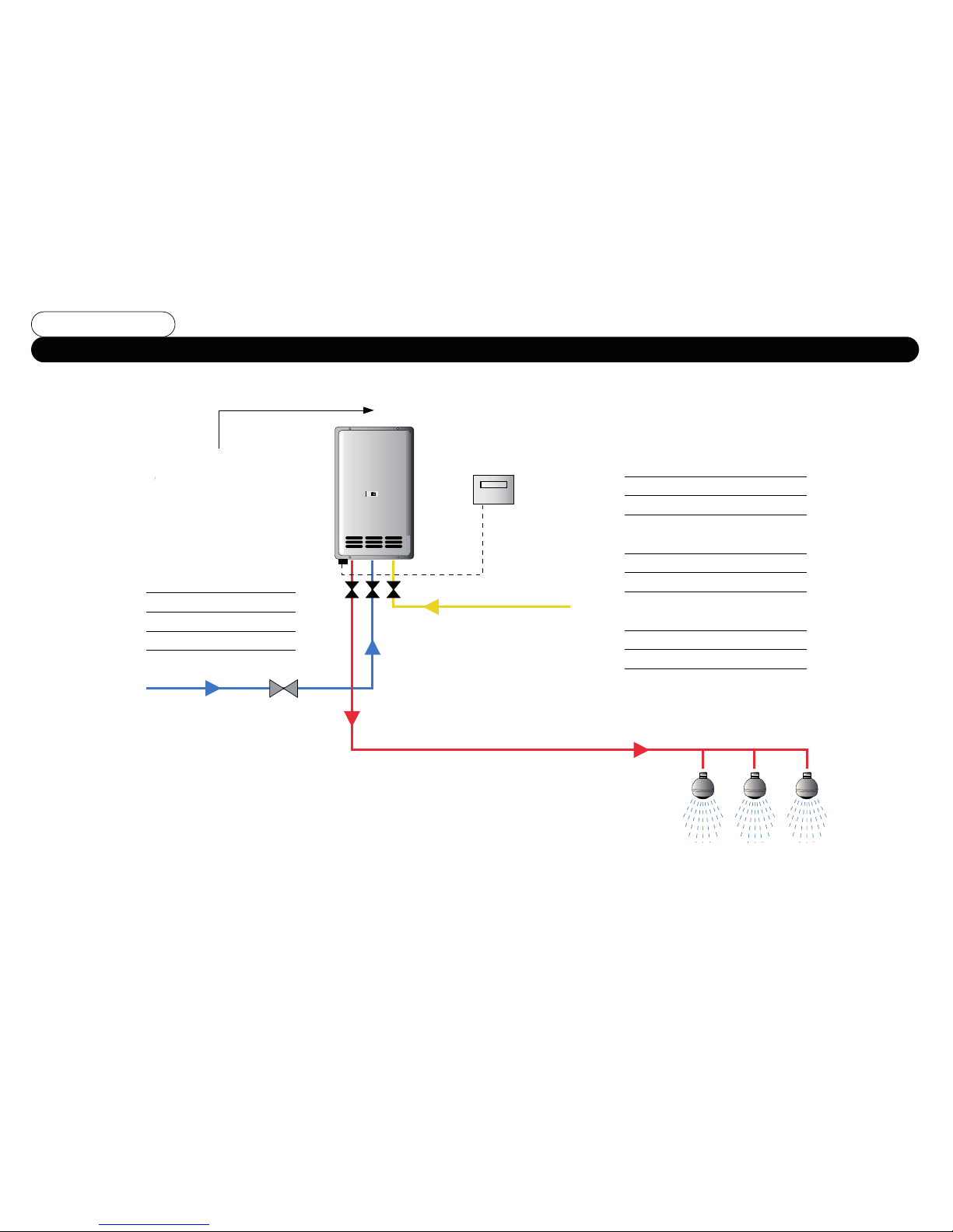
Please refer to the
FASTflo Specification
Sheet and Flue Selection
Guide for Flue Kit and
termination details
Remote controller kit
(part no. B285)
Gas
HWS flow
Hot Outlets
Water Supply Pressure
Min 1.0 bar
Max 10.0 bar
Min flow 3.5 ltrs/min
1. Stop cock
Gas rate for NG units
WH42 - 5.1 m3/hr
WH56, WHX56 - 6.5 m3/hr
Gas rate for Propane units
LWH42 - 1.9 m3/hr
LWH56, LWHX56 - 2.5 m3/hr
Dynamic Pressure
NG 20 mbar
Propane 37 mbar
1
Andrews WH and WHX Single Water Heater Installation Without Secondary Return
Fig No.1
Cold Supply
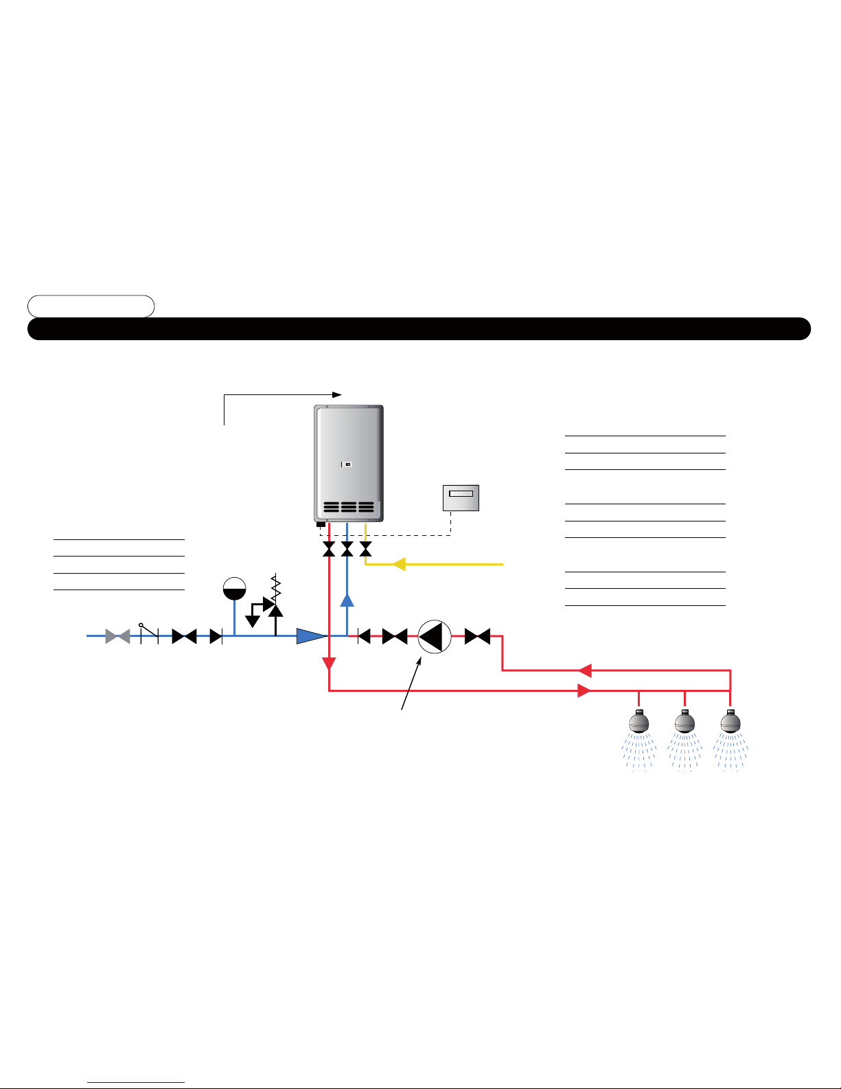
Please refer to the
FASTflo Specification
Sheet and Flue
Selection Guide for
Flue Kit and
termination details
Remote controller kit
(part no. B285)
Gas
HWS flow
Hot Outlets
Cold Supply
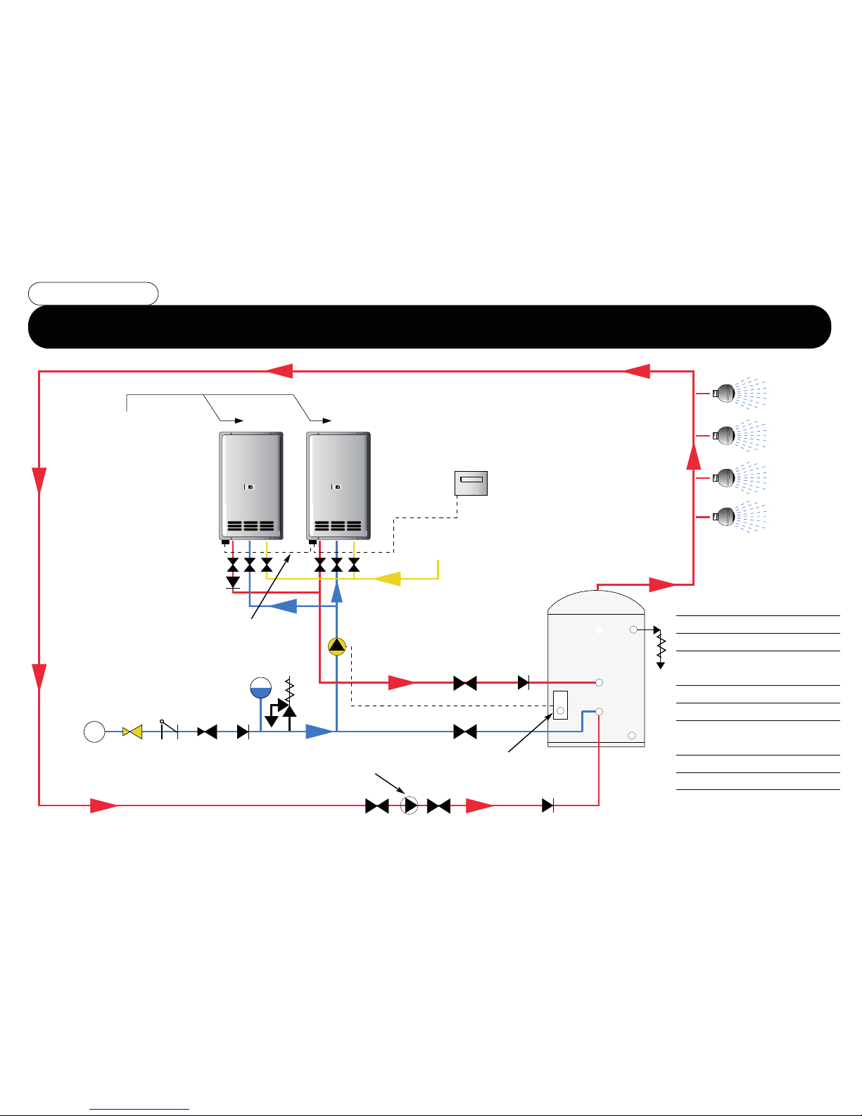
1. Stop cock
2. Strainer
3. Pressure reducing valve
4. Non return valve
5. Expansion vessel
6. Expansion valve + tundish
7. Andrews bronze pump c/w
ball valve unions (part no. B249)
Water Supply Pressure
Min 1.0 bar
Max 10.0 bar
Min flow 3.5 ltrs/min
Bronze secondary return pump
see Fig. No’s. 13 and 14
Gas rate for NG units
WH42 - 5.1 m3/hr
WH56, WHX56 - 6.5 m3/hr
Gas rate for Propane units
LWH42 - 1.9 m3/hr
LWH56, LWHX56 - 2.5 m3/hr
Dynamic Pressure
NG 20 mbar
Propane 37 mbar
123 4
5
6
7
Andrews WH and WHX Single Water Heater Installation with Secondary Return
Fig No.2

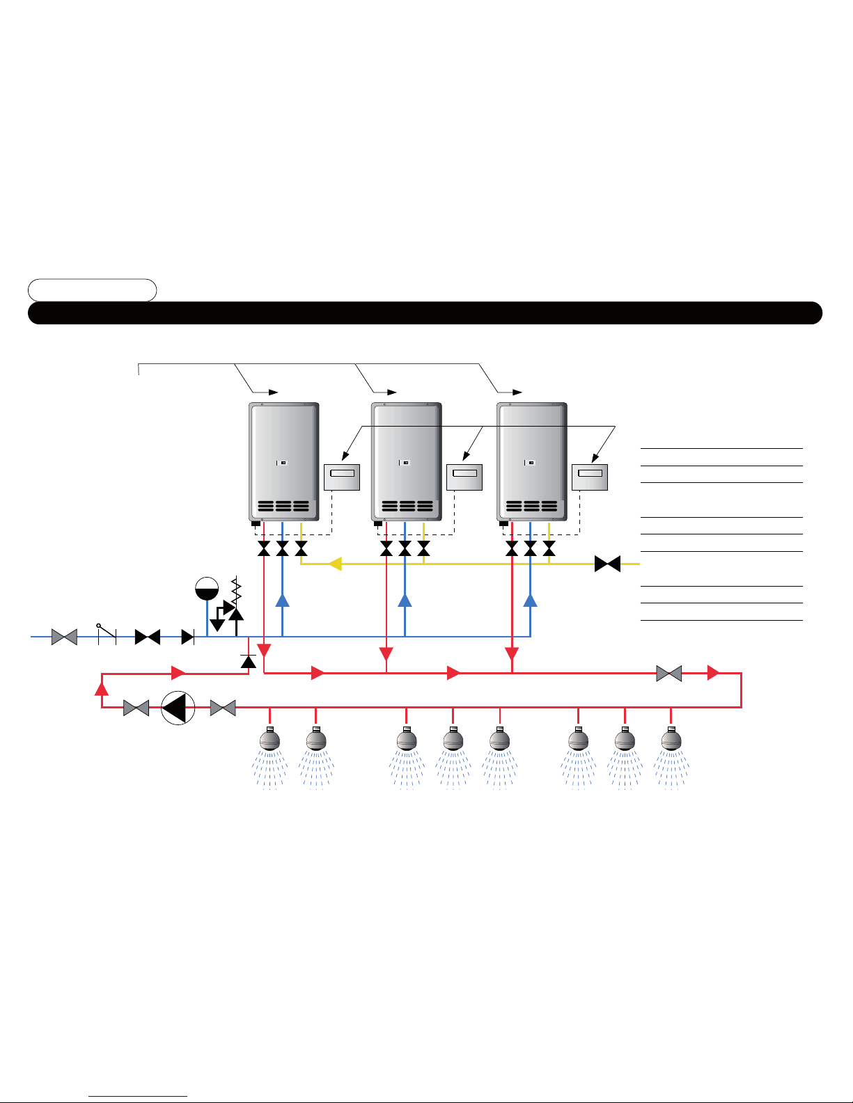
Remote controller kit
(part no. B285)
Gas
HWS flow Where output may be below
7 ltrs/min see Fig. No. 4
Cold Supply
1. Stop Cock
Water Supply Pressure
Min 1.0 bar
Max 10.0 bar
Gas rate for NG units
WH42 - 5.1 m3/hr
WH56, WHX56 - 6.5 m3/hr
Gas rate for Propane units
LWH42 - 1.9 m3/hr
LWH56, LWHX56 - 2.5 m3/hr
Dynamic Pressure
NG 20 mbar
Propane 37 mbar
1
Andrews WH and WHX Multiple Water Heater Installation without Secondary Return
Fig No.3
Please refer to the
FASTflo Specification
Sheet and Flue Selection
Guide for Flue Kit and
termination details

Andrews WH and WHX Multiple Water Heater Installation with Quick Connect Cord Kit
Fig No.4
Single remote
controller
Gas
HWS flow
Hot Outlets
Cold Supply
1. Stop Cock
Water Supply Pressure
Min 1.0 bar
Max 10.0 bar
Quick Connect Cord Kit
(part no. B286)
Gas rate for NG units
WH42 - 5.1 m3/hr
WH56, WHX56 - 6.5 m3/hr
Gas rate for Propane units
LWH42 - 1.9 m3/hr
LWH56, LWHX56 - 2.5 m3/hr
Dynamic Pressure
NG 20 mbar
Propane 37 mbar
1
Please refer to the
FASTflo Specification
Sheet and Flue Selection
Guide for Flue Kit and
termination details
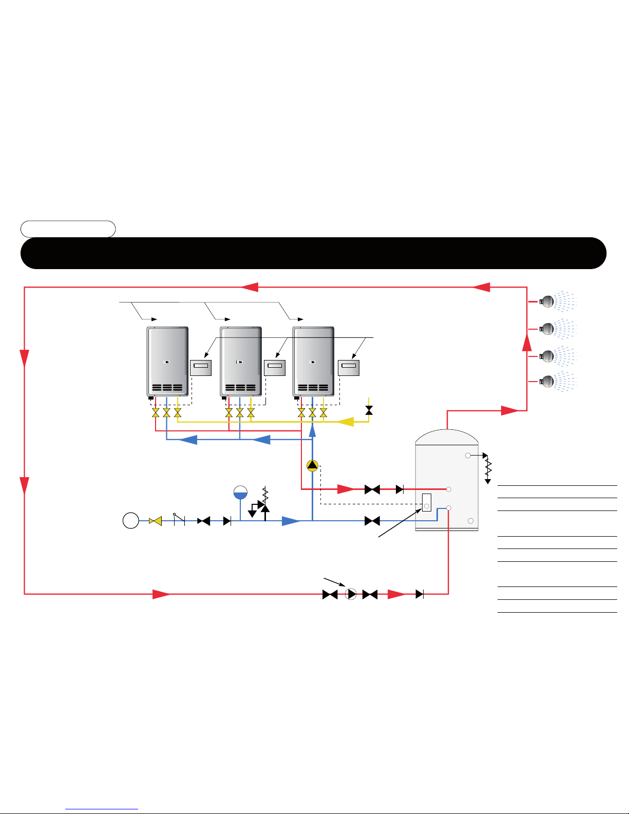
Andrews WH and WHX Multiple Water Heater Installation with Secondary Return
Fig No.5
Remote
controller
kit (part no
B285)*
*An Electronic System Controller Kit
can be used as an alternative when
manifolding up to six units. (see Fig.
No’s 6 and 8)
Gas
HWS flow
Hot Outlets
Cold Supply
Bronze secondary return pump
see Fig. No’s. 13 and 14
Gas rate for NG units
WH42 - 5.1 m3/hr
WH56, WHX56 - 6.5 m3/hr
Gas rate for Propane units
LWH42 - 1.9 m3/hr
LWH56, LWHX56 - 2.5 m3/hr
Dynamic Pressure
NG 20 mbar
Propane 37 mbar
1 2 3 4
7
5
6
4
Please refer to the
FASTflo Specification
Sheet and Flue Selection
Guide for Flue Kit and
termination details
1. Stop cock
2. Strainer
3. Pressure reducing valve
4. Non return valve
5. Expansion vessel
6. Expansion valve + tundish
7. Andrews bronze pump c/w
ball valve unions
(part no. B249)

Andrews WH56 and WHX56 Multiple Water Heater Installation with System Controller Kit
Fig No.6
Single remote
controller
System Controller in unit No. 1
(see Fig. No. 8)
Gas
HWS flow
Hot Outlets
Cold Supply
Gas rate per NG units
WH42 - 5.1 m3/hr
WH56, WHX56 - 6.5 m3/hr
Gas rate for Propane units
LWH42 - 1.9 m3/hr
LWH56, LWHX56 - 2.5 m3/hr
Dynamic Pressure
NG 20 mbar
Propane 37 mbar
1
1. Stop Cock
Water Supply
Pressure
Min 1.0 bar
Max 10.0 bar
Please refer to the
FASTflo Specification
Sheet and Flue
Selection Guide for
Flue Kit and
termination details

Andrews WH and WHX Water Flow Rates
Performance Chart
Fig No.7
Andrews Model Temperature Temperature Temperature Temperature Temperature Temperature
Reference
Rise 25ºC Rise 35ºC Rise 45ºC Rise 55ºC Rise 65ºC Rise 75ºC
L sec L min L sec L min L sec L min L sec L min L sec L min L sec L min
WH42,LWH42 0.40 24.0 0.29 17.4 0.22 13.2 0.18 10.8 0.15 9.2 0.13 8.0
WH56, LWH56 0.53 31.8 0.38 22.8 0.30 18.0 0.24 14.4 0.20 12.3 0.18 10.6
WHX56,LWHX56 0.53 31.8 0.38 22.8 0.30 18.0 0.24 14.4 0.20 12.3 0.18 10.6
The flow rate will vary dependant upon the temperature selected at outlet and the incoming water temperature.
The flow rate can be calculated using the following formula or by reference to the charts above.
In addition to the above the maximum flow through each heater is pre-set independent of temperature, maximum flow rate for the
WH42 is 24 L/min and maximum flow rate for the WH56 and WHX56 is 31.8 L/min.
WH42, LWH42 = 42 kW output
WH56, LWH56 = 55.8kW output
WHX56, LWHX56 = 55.8 kW output
(heater output) kW
Δt (temperature rise) x 4.2 specific heat
Flow rate L/S =
Water flow
at different
temperature
rises

Andrews System Controller Kit (Part No. B287) for WH56, LWH56, WHX56
Fig No.8
P
C
B
P
C
B
P
C
B
P
C
B
P
C
B
P
C
B
The System Controller Kit can be used as an alternative to the Quick Connect Cord Kit (two unit installation) or for controlling up to six
manifolded water heaters. The master unit (No.1) contains the System Controller module and includes plug connectors to enable the control
cords from the other units to be connected up to the master unit. In addition the System Controller incorporates the following standard
features, BEMS fault indication, Remote ‘Power On’ indication, Primary Pump connection via cylinder thermostat, Secondary Circulation
Pump connection and Remote Switching. A comprehensive installation manual is available from our sales department.
Single remote
controller
System controller Kit
(Part No. B287)
Typical installation
System operation
The control panel randomly selects some heaters at the ready stage and some at the standby stage, and heaters will start dependent upon
water flow and temperature settings. The system rotates the lead and standby units after every eight hours operating time. As the flow rates
increases additional units will fire thus maintaining the required system flow temperature. The remote controller must be connected to Unit
No. 1 and temperature settings on this controller will be communicated to the other manifolded heaters on the system. The System Controller
is not required when the installation incorporates a storage cylinder/ buffer vessel or if a constant large volume of hot water is required.
Unit No.1
Unit No.2Unit No.3
Unit No.4Unit No.5Unit No.6

Andrews WH & WHX Unvented System Kits
Fig No.9
If continuous flow water heaters are used on circulation systems or linked to a storage cylinder/buffer vessell
an unvented system kit is required to allow for expansion of the hot water system. The kit includes the
necessary safety devices required to conform to the current building regulations.
Three sizes of kit can be supplied and each contains a combined strainer/pressure reducing valve set to 3.5
bar, check valve, expansion valve set to 6.0 bar, tundish, 5 litre expansion vessel, wall bracket and hose.
When the system includes a storage cylinder/buffer vessel, a combined temperature/pressure relief valve
must be sized to suit the total input of all the water heaters installed (see table below).
This valve must be located at the top of the storage unit (see Fig. No. 10). In addition the size of the
expansion vessel must also be increased to suit both the storage cylinder plus the contents of the system
pipework (see expansion vessel table).
Unvented System Kit
Part No. Size
B235 3
/
4inch dia.
B234 1 inch dia.
B276 11
/
4inch dia.
Expansion Vessel
Part No. Size
C782 25 litre, 3.5 bar
C789 40 litre, 3.5 bar
E047 60 litre, 3.5 bar
C890 80 litre, 3.5 bar
Temperature and pressure Relief Valves Tundishes
Part No. Total Output Quantity & Size of Valves Part No. Size
C380
Up to 56kw 1 x 1 inch
C384 1 inch - 11
/
4inch
E242 Up to 112kw 1 x 11
/
2inch E326 1 1/2 inch - 2 inch
E242+C456 Up to 126kw 1 x 11
/
2inch + 1 x 3
/
4inch E497 2 inch - 21
/
2inch
E291 Up to 168kw 1 x 2 inch E497 2 inch - 21
/
2inch
E291+C380 Up to 224kw 1 x 2 inch + 1 x 1 inch E497+C384
2 inch - 21
/
2inch+ 1 inch - 11
/
4inch

Andrews WH and WHX Single Water Heater Installation with ST Range Storage Cylinder
Fig No.10
Remote
controller set
to 70ºCGas
Supply
Pump
(See Fig. No’s. 12/13)
HWS
flow
Storage
cylinder
Tank thermostat kit (part no.
C927) set to 65ºC
Cold Supply
NB. Size mains pressure group
to suit building design flow rate
Gas rate for NG units
WH42 - 5.1 m3/hr
WH56, WHX56 - 6.5 m3/hr
Gas rate for Propane units
LWH42 - 1.9 m3/hr
LWH56, LWHX56 - 2.5 m3/hr
Dynamic Pressure
NG 20 mbar
Propane 37 mbar
1 2 3 4
5
6
7
1. Stop cock
2. Strainer
3. Pressure reducing valve
4. Non return valve
5. Expansion vessel
6. Expansion valve + tundish
7. Andrews bronze pump c/w
ball valve unions (part no.
B249)
8. Combined temperature
and pressure relief valve
+ tundish
Please refer to the
FASTflo Specification
Sheet and Flue Selection
Guide for Flue Kit and
termination details
Hot Outlets
8
Andrews WH and WHX Multiple Water Heater Installation with ST Range Storage Cylinder,
Quick Connect Cord Kit and Secondary Return
Fig No.11
Remote controller
set to 70ºC
Gas
Supply
Pump
(See Fig. No’s. 12/13)
Quick connect
cord kit (part no.
B286)
HWS flow
Storage
cylinder
Tank thermostat kit (part
no. C927) set to 65ºC
Bronze secondary pump
Cold Supply
NB. Size mains pressure group to
suit building design flow rate
Gas rate for NG units
WH42 - 5.1 m3/hr
WH56, WHX56 - 6.5 m3/hr
Gas rate for Propane units
LWH42 - 1.9 m3/hr
LWH56, LWHX56 - 2.5 m3/hr
Dynamic Pressure
NG 20 mbar
Propane 37 mbar
1 2 3 4
5
6
7
1. Stop cock
2. Strainer
3. Pressure reducing valve
4. Non return valve
5. Expansion vessel
6. Expansion valve + tundish
7. Andrews bronze pump c/w
ball valve unions (part no.
B249)
8. Combined temperature
and pressure relief valve
+ tundish
Hot Outlets
Please refer to the
FASTflo Specification
Sheet and Flue Selection
Guide for Flue Kit and
termination details
8
Andrews WH and WHX Multiple Water Heater Installation with ST Range Storage Cylinder and
Secondary Return
Fig No.12
Gas
Supply HWS flow Hot Outlets
Storage
Cylinder
Tank thermostat kit (part
no. C927) set to 65ºC
Bronze secondary
pump
Cold Supply
NB. Size mains pressure group to
suit building design flow rate
Gas rate for NG units
WH42 - 5.1 m3/hr
WH56, WHX56 - 6.5 m3/hr
Gas rate for Propane units
LWH42 - 1.9 m3/hr
LWH56, LWHX56 - 2.5 m3/hr
Dynamic Pressure
NG 20 mbar
Propane 37 mbar
1 2 3 4
4
5
6
7
1. Stop cock
2. Strainer
3. Pressure reducing valve
4. Non return valve
5. Expansion vessel
6. Expansion valve + tundish
7. Andrews bronze pump c/w ball
valve unions (part no. B249)
8. Combined temperature
and pressure relief valve
+ tundish
When using multiple units in conjunction
with a storage vessel the full output of all
heaters is required to provide maximum
recovery volume. In this case the primary
pump must be sized to give 8 litres/min
for each heater. See Fig No’s. 12 and 13.
Pump
(See Fig.
No’s. 12/13)
Remote
controller
kit (part no
B285)*
*An Electronic System
Controller Kit can be used
as an alternative when
manifolding up to six units.
(see Fig. No’s 6 and 8)
Please refer to the
FASTflo Specification
Sheet and Flue Selection
Guide for Flue Kit and
termination details
68

Flow Rate Head Loss and Pump Sizing
Fig No.13
The WH and WHX units will operate within a water inlet pressure
range from 1.0 bar to 10.0 bar.
When a pump is used with a storagae system or for secondary
return circulation only bronze or stainless steel pumps must be used.
The pump must be sized to give a minimum flow rate of 8 L/min
through each heater.
The head loss through the FASTflo range of products is due to the
friction generated when the water flows through the heat exchanger
and associated components.
Water Flow (litres/minute)
Head Loss (bar)
0
2.5
2
1.5
1
0.5
0
510 15 20 25 30
A suitable 3 speed bronze pump kit with ball valve unions to 28mm cu. can
be supplied by Andrews, part no.B249 (see Fig No. 14)
Pump Selection using multiple heaters (pump required for first unit only)
Number of units Flow rate required Approximate head Speed setting
1 8 l/min - 0.13 l/sec 50 kPa 2
Pump selection using multiple heaters (flow through all units)
2 16 l/min - 0.27 l/sec 50 kPa 2
3 24 l/min - 0.40 l/sec 60 kPa 3
4 32 l/min - 0.53 l/sec 60 kPa 3
5 48 l/min - 0.67 l/sec 60 kPa 3
6 48 l/min - 0.80 l/sec 60 kPa 3

Pump Curves for Andrews 3 Speed Bronze Circulating Pump. Part No.B249
Fig No.14
0
P1
(W)
200
0 0.2
1
160
120
80
40
0
0.4 0.6 0.8 1.0 1.2 1.4 1.6 1.8 2.0 Q(1/s)
2
3
4
5
6
7
8
(m)
H
SPEED 3
SPEED 2
SPEED 1
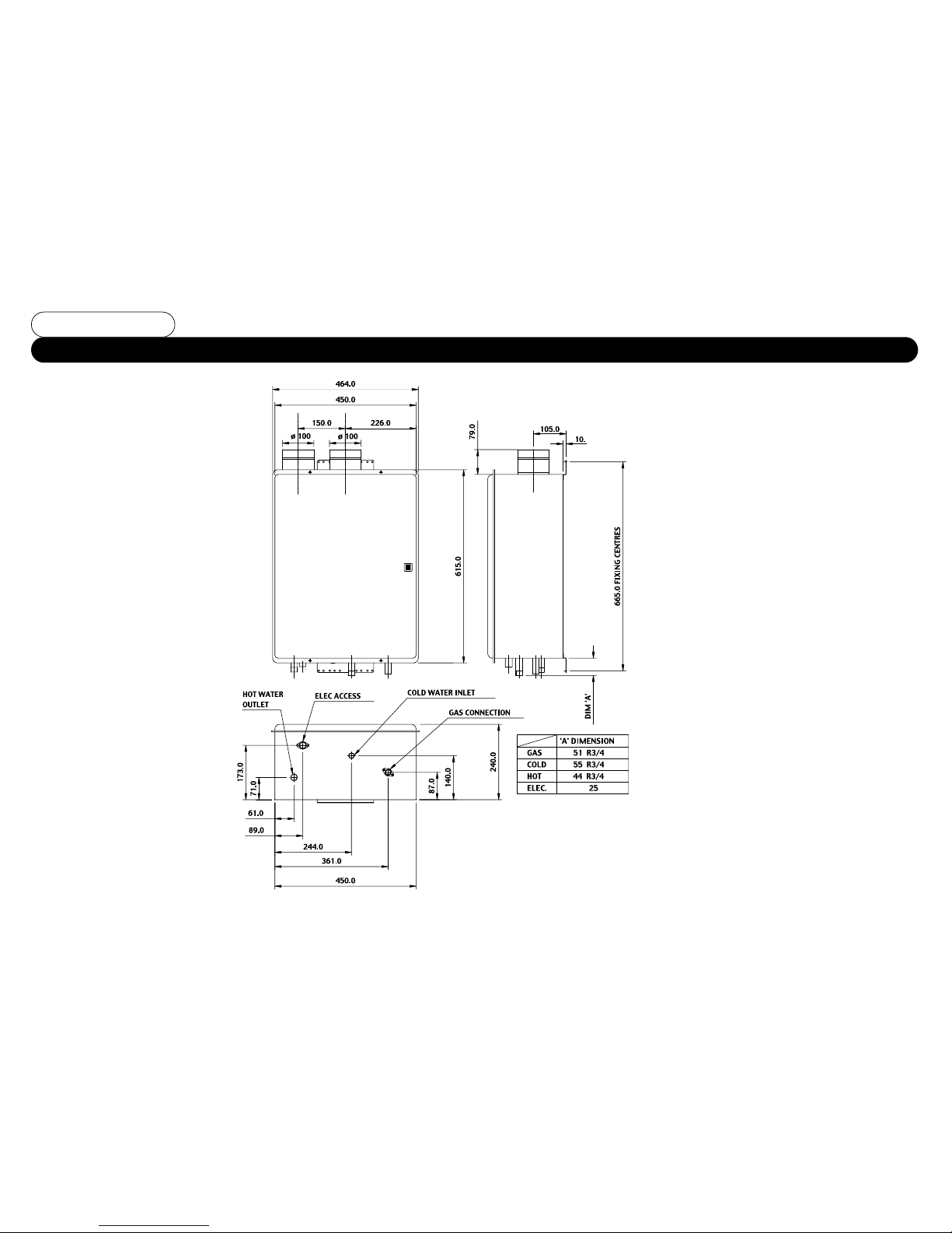
Dimensions WH42/LWH42/WH56 and LWH56
Fig No.15
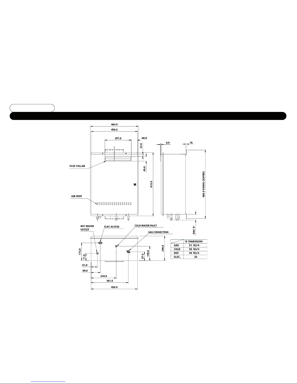
Dimensions WHX56 and LWHX56
Fig No.16

WH42, LWH42, WH56 and LWH56 Pre-assembled dual manifold unit dimensions
Fig No.17
This manual suits for next models
4
Table of contents
Popular Water Heater manuals by other brands


A.O. Smith
A.O. Smith aosbath D25A2 user guide

Weil-McLain
Weil-McLain C-1013 troubleshooting guide

Lochinvar
Lochinvar CH 600 PG CE Installation, commissioning, user & maintenance instructions

Sanyo
Sanyo SHP-TH90GDN-SW Technical manual

Bestway
Bestway Pool+ owner's manual

Lochinvar
Lochinvar 151 - 801 Operation manual

Graf
Graf RainHarvest Systems Top-Tank 323002 Installation instructions and maintenance

Nibe
Nibe UKV 200 installation instructions

STIEBEL ELTRON
STIEBEL ELTRON DHM 3 Operation and installation

Pentair
Pentair N20 instruction manual

Eurofred
Eurofred daitsu WITD-AQUATANK HP Series Installation and maintenance manual

Viessmann
Viessmann Vitocell 100-E Installation and service instructions