FAUDE C-Guide User manual

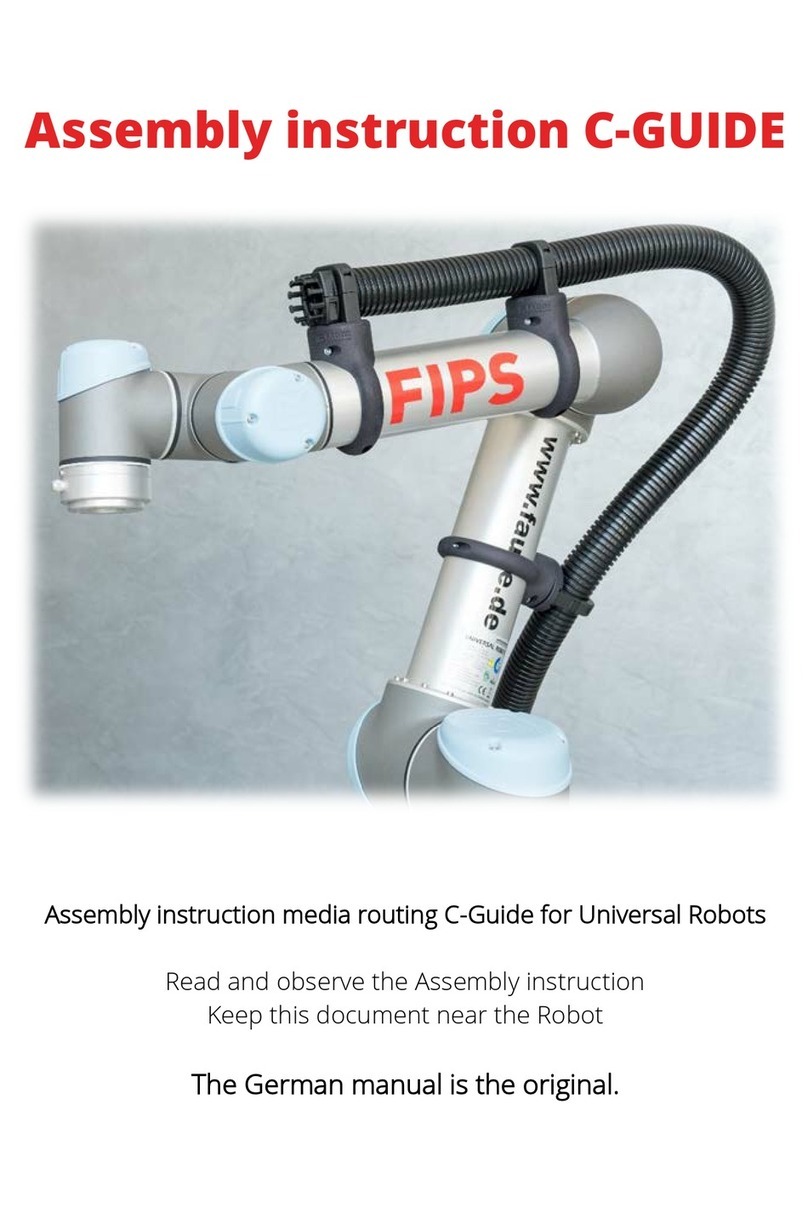
Assembly instruction C-GUIDE
Assembly instruction media routing C-Guide for Universal Robots
Read and observe the Assembly instruction
Keep this document near the Robot.

2
CONTENT
1. INCLUDED ITEMS...................................................................3
2. PRODUCT DESCRIPTION........................................................4
3. INSTALLATION ON THE ROBOT .............................................4
3.1 ASSEMBLY RIGID HOLDER.....................................................7
3.2 ASSEMBLY ROTATABLE HOLDER...........................................8
3.3 IMAGESDIRECTORY ...............................................................9
3.4 FURTHER ACCESSORIES FOR THE UR..................................10

3
1. INCLUDED ITEMS
The C-Guide for the UR3 consists of following parts.
Image1: Scope of supply C-Guide UR3
1. Fixed Holder with pressure interception
2. Media hose
3. Rotation bracket
4. Hose clamp
1
2
3
4

4
2. PRODUCT DESCRIPTION
FAUDE offers the possibility by the attachment of the media routing C-
Guide of supplying electrical and pneumatic lines over the robot to the final
effector.
Due to the innovative robust design of the C-Guide the lines are guided safely
and flexible along the robot. The design allows a long lifetime without kinks or
injuries at the lines and hoses in every robot position.
3. INSTALLATION ON THE ROBOT
The following chapter describes the assembly of the FAUDE C-Guides at the
Universal Robot UR3.
The UR3 must be built up and be able to work before you can start with the
assembly of the C-Guide. The following illustration shows a robot
construction that allows easy assembly of the C-Guide.
Image 2: Possible position for the assembly

5
The C-Guide of the UR3 is kept safely on the robot arm by the two included
holders. The holders are one fixed holder with a cable clamp and a rotatable
holder. These holders are preassembled at delivery like in Image 1. Before
mounting the holders you have to disassembly them first by unscrewing the
three Hexagon head screws M4x20 (size 3) on each holder.
Image 3: Explosion view of the C-Guide holders
The fixed holder with the cable clamp is fastened at the forearm, the
rotatable holder at the upper arm of the robot. It has to be taken care at the
assembly of the rigid holder that the comb which serves for the cable clamp
of the tubes and lines, points in the direction of the robot tool. There isn’t any
predefined orientation for the rotatable holder. Moreover, it has to be taken
care at the attachment of the C-Guide that the surface of both robot arms
are free from oil and dust. If this is not the case all robots from the Company
Universal Robot can be cleaned with a customary industry cleaner. The care
notes of the operator’s manual have to be taken into account.

6
Image 4: UR3 with mounted C-Guide holders
The hose clamp listed under position 5 in the description of included parts is
used to attach the media hose to the system part, the table plate etc. on
which the robot is mounted. This is to be mounted individually as a result of
the requirements.
Forearm
Rigid holder
Cable clamb
Rotation bracket
Upper arm

7
Image 5: Forearm with one part of the holder
Image 6: Forearm with both parts of the holder
Image 7: Forearm with C-Guide
3.1 ASSEMBLY RIGID HOLDER
After opening the three
M4x20 screws the rigid
holder can be pulled apart.
The comb for the cable
clamping as well as the tube
holder remain on one side
of the C- Guide holder each.
Then one side of the holder
is placed on the forearm.
When this is done, the
second side of the holder is
put on.Afterwards the
three Hexagon head screws
M4x20 (size 3) have to be
tightened. Please ensure
that all screws are
tightened evenly.
At the last step of the
assembly of the rigid C-
Guide holder, the media
hose will be clipped into the
holder.

8
Image 8: Upper arm with one side of the holder
Image 9: Upper arm with one side of the holder
3.2 ASSEMBLY ROTATABLE HOLDER
After opening the three screws
(M4x20) the rotatable holder can
be pulled apart. The ball bearing,
including the hose holder,
remains on one side of the C-
guide holder. After that, one side
of the holder has to be put on
the robot arm.
When this is done, the second
side of the holder is put on.
Afterwards the three Hexagon
head screws M4x20 (size 3) have
to be tightened. Please ensure
that all screws are tightened
evenly
At the last step of the
assembly of the rotatable C-
Guide holder, the media hose
will be clipped into the holder.
Image 10: Upper arm with both sides of the holder

9
Image 11: UR3 complete mounted C-Guide
3.3 IMAGESDIRECTORY
Image 1: Scope of supply C-Guide UR3......................................................................3
Image 2: Possible positions for the assembly...........................................................4
Image 3: Explosion view of the C-Guide holders......................................................5
Image 4: UR3 with mounted C-Guide holders ..........................................................6
Image 5: Forearm with one part of the holder .........................................................7
Image 6: Forearm with both parts of the holder......................................................7
Image 7: Forearm with C-Guide....................................................................................7
Image 8: Upper arm with one side of the holder.....................................................8
Image 9: Upper arm with both sides of the holder .................................................8
Image 10: Upper arm with C-Guide.............................................................................8
Image 11: UR3 with complete mounted C-Guide ...................................................9

10
3.4 FURTHER ACCESSORIES FOR THE UR
PROLIGHT
When implementing HRC applications, special
requirements must be met.
In particular, the standards and guidelines for the
components must be observed, so that injuries to
employees cannot occur. This also includes the
connection socket of axis 6 on the UR3 and UR5
robots. This must be additionally secured.
Furthermore, operators are obligated to show that
the robot is active by a corresponding visualization.
FAUDE offers the ProLight lighting protection ring for this purpose
This is used to meet the safety requirements of industrial robots for safe “human - robot
collaborations”.
Order number: PROLIGHT: FAP17101
SACA- SAFETY- CASE
The requirements of an enabled device according to
DIN EN ISO 10218-1 are fulfilled with the retrofit of the
UR teach panels with the SaCa safety case, including
the 3-level enabling switch.
Single-handed ergonomic
operation permits additional
actuation of the button for
freedrive mode. This means
one hand is free for manual guidance of the robot. It is suitable for both
left and right handed operation.
With the 3-point set down the operating panel is available at any time for
safe and comfortable programming.
Order number: SACA- SAFETY- CASE: FAP16610

11
SAFETY- BUNDLE
According to the professional association and the standards for robots, whether it is a
lightweight robot or an HRC robot, the current robot standard DIN EN ISO 10218-1 must be
fulfilled.
It is stated there that each robot requires a mode selector and an enabling switch.
The safety system from FAUDE fulfills this with consideration of the two-channel and adaptation
of the user interface.
The FAUDE safety bundle expands the
UR robots with additional functions to
increase the safety and fulfilment of
safety specifications on industrial robots
(DIN EN ISO 10218-1).
The specified operating mode selection is
ensured by the Electronic Key System
(EKS). The EKS is used to manage access
and control of the system using an
electronic key with different authorisation
levels. Using a 3-level enabling switch on
the FAUDE safety case, the requirement
for an enabling device for set up mode is
fulfilled.
While the operator (black) can only start
and stop the system, the programmer
(green) can adjust the teach points in a specific area.
The maintenance person, on the contrary, has with the access authorization all possibilities to
put the robot into operation or to reorient it.
Using the Siemens S7 safety controls other external devices via PROFINET or PROFIsafe can be
connected.
Order number: SAFETY- BUNDLE: FAP16610

FAUDE Automatisierungstechnik GmbH
Max-Planck-Str. 10 – 71116 Gaertringen – Germany
Telephone +49-7034-2567-0 – Fax-67
Email: mailto:faude@faude.de – Web: www.faude.de/
Other manuals for C-Guide
1
Table of contents
Other FAUDE Robotics manuals
